AI Engine DevelopmentSee Vitis™ Development Environment on xilinx.com See Vitis-AI™ Development Environment on xilinx.com |
Window Based AI Engine Kernels
This example shows you how to construct a graph with packet switching capability. In the first section, Construct Graph with Packet Switching Capability, the example graph features:
Four parallel AI Engine kernels, with all four kernels sharing the same input and output ports to the PL.
AI Engine kernels using window interfaces, which means they are agnostic about how data is communicated to the PL.
This section introduces two new templated node classes, pktsplit<n> and pktmerge<n>, to construct the graph. These classes switch the packet to the correct destination and construct the packet with the corresponding packet IDs, respectively.
Then this example:
Introduces the Packet Format and how to Prepare Data and Run AI Engine Simulator.
Introduces a system design that includes Example PL Kernels for Packet Switching. In the example PL kernels, you can see how a packet is constructed and how the packet ID generated by the AI Engine compiler is used.
Shows PS code for the system design in Example PS code for Packet Switching.
Shows how to Run Hardware Emulation and Hardware flows.
Construct Graph with Packet Switching Capability
To explicitly control the multiplexing and de-multiplexing of packets, two new templated node classes are added to the ADF graph library: pktsplit<n> and pktmerge<n>. A node instance of class pktmerge<n> is a n:1 multiplexer of n packet streams producing a single packet stream. A node instance of class pktsplit<n> is a 1:n de-multiplexer of a packet stream producing n different packet streams.
Note: The maximum number of allowable packet streams is thirty-two on a single physical channel (n≤32).
The data from the PLIO is first connected to the pktsplit<n> instance, which splits the packet depending on the packet ID. It automatically discards the packet header and fills the window input buffers. It automatically discards the TLAST signal of the packet when the window data is fully filled.
Each AI Engine kernel works similarly to a non-packet switching kernel. The output data is merged by the pktmerge<n> instance, which automatically inserts the packet headers with packet IDs, and TLAST for the last data of the packet.
Hint: Make sure the packet length matches the window size for either kernel input or output window.
Change the working directory to window_aie. The example graph code is in aie/graph.h, shown as follows.
class mygraph: public adf::graph {
private:
  adf:: kernel core[4];

  adf:: pktsplit<4> sp;
  adf:: pktmerge<4> mg;
public:
  adf::port<input>  in;
  adf::port<output>  out;
  mygraph() {
    core[0] = adf::kernel::create(aie_core1);
    core[1] = adf::kernel::create(aie_core2);
    core[2] = adf::kernel::create(aie_core3);
    core[3] = adf::kernel::create(aie_core4);
    adf::source(core[0]) = "aie_core1.cpp";
    adf::source(core[1]) = "aie_core2.cpp";
    adf::source(core[2]) = "aie_core3.cpp";
    adf::source(core[3]) = "aie_core4.cpp";

    sp = adf::pktsplit<4>::create();
    mg = adf::pktmerge<4>::create();
    for(int i=0;i<4;i++){
      adf::runtime<ratio>(core[i]) = 0.9;
      adf::connect<adf::pktstream, adf::window<32> > (sp.out[i], core[i].in[0]);
      adf::connect<adf::window<32>, adf::pktstream > (core[i].out[0], mg.in[i]);
    }
    adf::connect<adf::pktstream> (in, sp.in[0]);
    adf::connect<adf::pktstream> (mg.out[0], out);
  }
};
This is a graph with a 4:1 splitter pktsplit<4> and 1:4 merger pktmerge<4>. Note that the connection type for pktsplit and pktmerge is adf::pktstream. The input port in is first connected to the pktsplit, and pktsplit switches the packets to different AI Engine kernels. The outputs of AI Engine kernels are connected to the pktmerge, and pktmerge generates packet headers for those packets automatically and outputs them through output port, out.
Run the make command make aie to compile the graph. Then open the compiled summary with the Vitis™ analyzer using the command vitis_analyzer ./Work/graph.aiecompile_summary. Then click the Graph tab in the Vitis analyzer. The graph of the design is shown as follows.
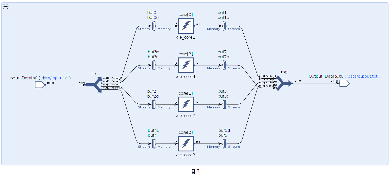
It is seen that every sp output has been assigned a unique packet ID. Also, every mg input has been assigned a unique ID. The packet IDs can vary on different implementations. The AI Engine compiler generates a JSON file that contains all the packet ID infomation Work/reports/packet_switching_report.json. It also generates header files that define unique macro variables for the packet IDs. These files are Work/temp/packet_ids_c.h and Work/temp/packet_ids_v.h, which can be directly included in the C or Verilog source code.
For example, in this test case, the Work/temp/packet_ids_c.h file is as follows.
#define Datain0_0 0
#define Datain0_1 1
#define Datain0_2 2
#define Datain0_3 3
#define Dataout0_0 3
#define Dataout0_1 2
#define Dataout0_2 1
#define Dataout0_3 0
The macro names Datain0_0, …, Dataout0_3 do not change between different compilations. You can see how these macros are used in the PL kernels in this test case in a later section.
Packet Format
The first 32-bit word of a packet must always be a packet header which encodes several bit fields, as shown in the following table.
| Bit | Note |
|---|---|
| 4-0 | Packet ID |
| 11-5 | 7'b0000000 |
| 14-12 | Packet Type |
| 15 | 1'b0 |
| 20-16 | Source Row |
| 27-21 | Source Column |
| 30-28 | 3'b000 |
| 31 | Odd parity of bits[30:0] |
The packet ID in the header should match the ID assigned by the compiler. The packet type can be any 3-bit pattern that you want to insert to identify the type of packet. The source row and column denote the AI Engine tile coordinates from where the packet originated. By convention, source row and column for packets originating in the PL is -1,-1.
The last 32-bit word should have its TLAST set High. Other words should set their TLAST Low.
When the packet originates from the PL, the packet header should be constructed by the PL kernels manually. When the AI Engine receives the packet, it is decoded and routed to the destination corresponding to the packet ID in the header.
When the packet originates from the AI Engine, the first 32-bit word should be decoded by the PL kernels manually. By decoding the packet ID from the packet, and reading the packet switching header files (Work/temp/packet_ids_c.h and Work/temp/packet_ids_v.h) by the compiler, the PL kernels should be able to route the packet to the correct destination.
Prepare Data and Run AI Engine Simulator
When constructing the input data file for the AI Engine simulator, the data file should contain the sequence of packets. Each packet contains the packet header, follwed by the data. The last data has the TLAST keyword in a separate line just above the data. The data is in 32-bit integer format, including the header. The following is an example of a packet in the data file (data/input.txt).
2415853568
0
1
2
3
4
5
6
TLAST
7
In this packet, 2415853568 is an integer. The hex value for 2415853568 is 0x8FFF0000, which has packet ID of 0 (the last five bits). It is useful for you to have your own program to convert the original data into the data file with packet headers in the required format.
When the input PLIO is not 32 bits wide, it can include multiple 32-bit integers in a line to construct wider bit words, with spaces between them. For example, the following is an example packet for a 64-bit width PLIO.
2415853568 0
1 2
3 4
5 6
TLAST
7
Run the AI Engine simulator with following make command. The detailed information for the AI Engine compiler and AI Engine simulator commands can be found in AI Engine Documentation.
make aiesim
The output data is in aiesimulator_output/data/output.txt. The output data is also arranged as sucessive packets, for example:
T 413 ns
50462720
T 416 ns
4
T 417 ns
8
T 418 ns
12
T 419 ns
16
T 420 ns
20
T 421 ns
24
T 422 ns
28
T 423 ns
TLAST
32
The packet header is the first 32-bit word 50462720. Its hex value is 0x3020000. Therefore the packet ID is 0 (the last 5 bits). You can look at the packet switching header files (Work/temp/packet_ids_c.h and Work/temp/packet_ids_v.h) to find out which AI Engine kernel has produced it. The Work/temp/packet_ids_c.h has defined:
#define Dataout0_3 0
Here, Dataout0_3 denotes that the packet ID 0 comes from pktmerge.in[3]. By looking at the graph code (aie/graph.h) or graph view in Vitis analyzer, you can find which AI Engine kernel actually produced it. In this example result, it is kernel core[3] (aie/aie_core4.cpp).
Example PL Kernels for Packet Switching
This section describes how the PL kernels can generate and decode packet headers, and how to distribute packets to the corresponding destinations. HLS example code is provided, and hardware emulation and hardware flows can be run.
The packet switching feature does not have a dependency on the PL kernel types (HLS, Verilog, etc) and their design structure. It just has requirements around the packet format and how the packet ID works as described in the previous sections.
The system design structure of the example is as shown in the following image.
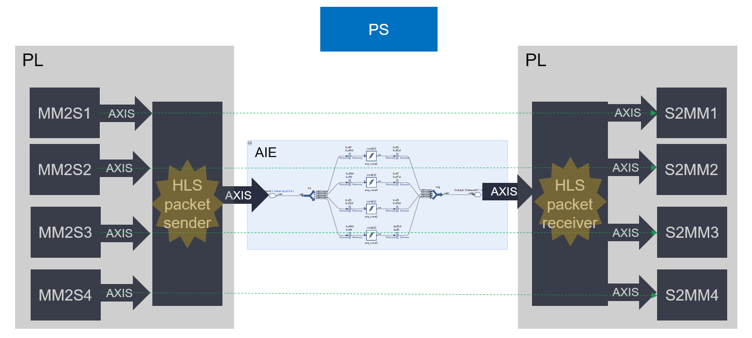
The previous section introduced the AI Engine side. It receives packets from one PLIO (AXI4-Stream interface), and distributes the packets to different AI Engine kernels. Then all AI Engine outputs are packed with packet headers automatically and sent to one PLIO.
In this example, the PL kernel mm2s1 sends raw data to the HLS packet sender module, and the HLS packet sender module generates packets that match the packet switching requirements. It goes through the AI Engine kernel, core[0] (aie/aie_core1.cpp). Then the HLS packet receiver module decodes the packet header and sends the raw data to the PL kernel, s2mm1. Similarly, PL kernel, mm2s2, sends a message to PL kernel, s2mm2. And it is the same for mm2s3 to s2mm3 and mm2s4 to s2mm4.
Only the HLS packet sender module and HLS packet receiver module deal with the packet IDs generated by the AI Engine compiler. Other PL kernels focus on the data processing.
In this example, the four mm2s kernels are created by the --nk option of Vitis (v++) linker. The same applies for the s2mm kernels. You can look at system.cfg to see how all PL kernels are created and connected:
[connectivity]
nk=s2mm:4:s2mm_1.s2mm_2.s2mm_3.s2mm_4
nk=mm2s:4:mm2s_1.mm2s_2.mm2s_3.mm2s_4
nk=hls_packet_sender:1:hls_packet_sender_1
nk=hls_packet_receiver:1:hls_packet_receiver_1
stream_connect=hls_packet_sender_1.out:ai_engine_0.Datain0
stream_connect=ai_engine_0.Dataout0:hls_packet_receiver_1.in

stream_connect=mm2s_1.s:hls_packet_sender_1.s0
stream_connect=mm2s_2.s:hls_packet_sender_1.s1
stream_connect=mm2s_3.s:hls_packet_sender_1.s2
stream_connect=mm2s_4.s:hls_packet_sender_1.s3
stream_connect=hls_packet_receiver_1.out0:s2mm_1.s
stream_connect=hls_packet_receiver_1.out1:s2mm_2.s
stream_connect=hls_packet_receiver_1.out2:s2mm_3.s
stream_connect=hls_packet_receiver_1.out3:s2mm_4.s
Next review the HLS packet sender module in pl_kernels/hls_packet_sender.cpp. You can review the packet format in the previous section if necessary. The packet ID is generated by the function, generateHeader. Pay special attention to how it sends the packet header and reads data from the corresponding PL kernels:
#include "hls_stream.h"
#include "ap_int.h"
#include "ap_axi_sdata.h"
#include "packet_ids_c.h"

static const unsigned int pktType=0;
static const int PACKET_NUM=4; //How many kernels do packet switching
static const int PACKET_LEN=8; //Length for a packet

static const unsigned int packet_ids[PACKET_NUM]={Datain0_0, Datain0_1, Datain0_2, Datain0_3}; //macro values are generated in packet_ids_c.h

ap_uint<32> generateHeader(unsigned int pktType, unsigned int ID){
#pragma HLS inline
  ap_uint<32> header=0;
  header(4,0)=ID;
  header(11,5)=0;
  header(14,12)=pktType;
  header[15]=0;
  header(20,16)=-1;//source row
  header(27,21)=-1;//source column
  header(30,28)=0;
  header[31]=header(30,0).xor_reduce()?(ap_uint<1>)0:(ap_uint<1>)1;
  return header;
}

void hls_packet_sender(hls::stream<ap_axiu<32,0,0,0>> &s0,hls::stream<ap_axiu<32,0,0,0>> &s1,hls::stream<ap_axiu<32,0,0,0>> &s2,hls::stream<ap_axiu<32,0,0,0>> &s3,
  hls::stream<ap_axiu<32,0,0,0>> &out, const unsigned int num){
  for(unsigned int iter=0;iter<num;iter++){
    for(int i=0;i<PACKET_NUM;i++){//Iterate on PL kernels that do packet switching
      unsigned int ID=packet_ids[i];
      ap_uint<32> header=generateHeader(pktType,ID); //packet header
      ap_axiu<32,0,0,0> tmp;
      tmp.data=header;
      tmp.keep=-1;
      tmp.last=0;
      out.write(tmp);
      for(int j=0;j<PACKET_LEN;j++){ //packet data
        switch(i){//based on which kernel is sending packet, read the corresponding stream
        case 0:tmp=s0.read();break;
        case 1:tmp=s1.read();break;
        case 2:tmp=s2.read();break;
        case 3:tmp=s3.read();break;
        }
        if(j==PACKET_LEN-1){
          tmp.last=1; //last word in a packet has TLAST=1
        }else{
          tmp.last=0;
        }
        out.write(tmp);
      }
    }
  }
}
Now, review the HLS packet receiver module in pl_kernels/hls_packet_receiver.cpp. The packet ID is retrieved from the packet header by the function, getPacketId. Note how it sends the packet data to the corresponding PL kernels:
#include "hls_stream.h"
#include "ap_int.h"
#include "ap_axi_sdata.h"
#include "packet_ids_c.h"

static const int PACKET_NUM=4;
static const int PACKET_LEN=8;

static const unsigned int packet_ids[PACKET_NUM]={Dataout0_0, Dataout0_1, Dataout0_2, Dataout0_3};

unsigned int getPacketId(ap_uint<32> header){
#pragma HLS inline
  ap_uint<32> ID=0;
  ID(4,0)=header(4,0);
  return ID;
}

void hls_packet_receiver(hls::stream<ap_axiu<32,0,0,0>> &in, hls::stream<ap_axiu<32,0,0,0>> &out0,hls::stream<ap_axiu<32,0,0,0>> &out1,hls::stream<ap_axiu<32,0,0,0>> &out2,hls::stream<ap_axiu<32,0,0,0>> &out3,
  const unsigned int total_num_packet){
    for(unsigned int iter=0;iter<total_num_packet;iter++){
      ap_axiu<32,0,0,0> tmp=in.read();//first word is packet header
      unsigned int ID=getPacketId(tmp.data);
      unsigned int channel=packet_ids[ID];
      for(int j=0;j<PACKET_LEN;j++){
        tmp=in.read();
        switch(channel){
        case 0:out0.write(tmp);break;
        case 1:out1.write(tmp);break;
        case 2:out2.write(tmp);break;
        case 3:out3.write(tmp);break;
        }
      }
  }
}
Note that for both packet sender and packet receiver, the packet IDs are read from packet_ids_c.h, which is generated by the AI Engine compiler. Therefore, it requires that the AI Engine compilation is completed before the PL kernel compilation. Or, if packet IDs are changed when the AI Engine side has had any change, it requires the PL kernels to be re-compiled.
Example PS code for Packet Switching
The PS code for hardware emulation and hardware flows is in sw/host.cpp. You can review the code. It opens the XCLBIN using the following code.
 // Open xclbin
 auto dhdl = xrtDeviceOpen(0);//device index=0
 ret=xrtDeviceLoadXclbinFile(dhdl,xclbinFilename);
 xuid_t uuid;
 xrtDeviceGetXclbinUUID(dhdl, uuid);
It allocates buffers for mm2s kernels and s2mm kernels:
// output memory
xrtBufferHandle out_bo1 = xrtBOAlloc(dhdl, mem_size, 0, /*BANK=*/0);
...
int *host_out1 = (int*)xrtBOMap(out_bo1);
...
// input memory
xrtBufferHandle in_bo1 = xrtBOAlloc(dhdl, mem_size, 0, /*BANK=*/0);
...
int *host_in1 = (int*)xrtBOMap(in_bo1);
...
It initializes the input memory and then syncs the input memory:
// initialize input memory
for(int i=0;i<mem_size/sizeof(int);i++){
  *(host_in1+i)=i;
  *(host_in2+i)=2*i;
  *(host_in3+i)=3*i;
  *(host_in4+i)=4*i;
}
// sync input memory
xrtBOSync(in_bo1, XCL_BO_SYNC_BO_TO_DEVICE , mem_size,/*OFFSET=*/ 0);
...
Then it starts the output kernels and input kernels:
// start output kernels
xrtKernelHandle s2mm_k1 = xrtPLKernelOpen(dhdl, uuid, "s2mm:{s2mm_1}");
xrtRunHandle s2mm_r1 = xrtRunOpen(s2mm_k1);
xrtRunSetArg(s2mm_r1, 0, out_bo1);
xrtRunSetArg(s2mm_r1, 2, mem_size/sizeof(int));
xrtRunStart(s2mm_r1);
...
xrtKernelHandle hls_packet_receiver_k = xrtPLKernelOpen(dhdl, uuid, "hls_packet_receiver");
xrtRunHandle hls_packet_receiver_r = xrtRunOpen(hls_packet_receiver_k);
xrtRunSetArg(hls_packet_receiver_r, 5, total_packet_num);
xrtRunStart(hls_packet_receiver_r);

// start input kernels
xrtKernelHandle mm2s_k1 = xrtPLKernelOpen(dhdl, uuid, "mm2s:{mm2s_1}");
xrtRunHandle mm2s_r1 = xrtRunOpen(mm2s_k1);
xrtRunSetArg(mm2s_r1, 0, in_bo1);
xrtRunSetArg(mm2s_r1, 2, mem_size/sizeof(int));
xrtRunStart(mm2s_r1);
...
xrtKernelHandle hls_packet_sender_k = xrtPLKernelOpen(dhdl, uuid, "hls_packet_sender");
xrtRunHandle hls_packet_sender_r = xrtRunOpen(hls_packet_sender_k);
xrtRunSetArg(hls_packet_sender_r, 5, packet_num);
xrtRunStart(hls_packet_sender_r);
Then it starts the graph:
// start graph
adf::registerXRT(dhdl, uuid);
gr.run(2); //Iteration number=2. The amount of data matches for PL kernels and graph
Then it waits for s2mm kernels to complete, and syncs output memory:
// wait for s2mm to complete
xrtRunWait(s2mm_r1);
...
// sync output memory
xrtBOSync(out_bo1, XCL_BO_SYNC_BO_FROM_DEVICE , mem_size,/*OFFSET=*/ 0);
...
Then, finally, it performs post-processing and releases objects.
Note that there is no special packet switching handling in the PS code. It is already done on the AI Engine and PL side.
Run Hardware Emulation and Hardware flows
Run HW emulation with the following make command (it builds the HW system and host application).
make run_hw_emu
Hint: If the keyboard is accidentally hit and stops the system booting automatically, type boot at the Versal> prompt to resume the system booting.
After Linux has booted, run the following commands at the Linux prompt (this is only for HW cosim).
mount /dev/mmcblk0p1 /mnt
cd /mnt
export XILINX_XRT=/usr
export XCL_EMULATION_MODE=hw_emu
./host.exe a.xclbin
To exit QEMU press Ctrl+A, x
To run in hardware, first build the system and application using the following make command.
make package TARGET=hw
After Linux has booted, run the following commands at the Linux prompt.
export XILINX_XRT=/usr
cd /mnt/sd-mmcblk0p1
./host.exe a.xclbin
The host code is self-checking; it checks the correctness of the output data. If the output data is correct, after the run has completed, it will print:
TEST PASSED
Conclusion
In this step, you learned about the following concepts.
Constructing packet switching graph
Packet format and preparing data for the AI Engine simulator
Designing PL kernels for packet switching
PS application and running HW/HW emulation flows
Next, review Window Based AI Engine Kernels with Mixed Data Types
Licensed under the Apache License, Version 2.0 (the “License”); you may not use this file except in compliance with the License. You may obtain a copy of the License at
http://www.apache.org/licenses/LICENSE-2.0
Unless required by applicable law or agreed to in writing, software distributed under the License is distributed on an “AS IS” BASIS, WITHOUT WARRANTIES OR CONDITIONS OF ANY KIND, either express or implied. See the License for the specific language governing permissions and limitations under the License.
XD029 | © Copyright 2020-2021 Xilinx, Inc.