2021.1 Vitis™ Application Acceleration Development Flow TutorialsSee 2020.2 Vitis Application Acceleration Development Flow Tutorials |
Package IP/Package XO Flow
The process described in this lab follows the Package IP/Package XO flow as described in the RTL Kernel Development Flow in the Application Acceleration Development flow of the Vitis Unified Software Platform Documentation (UG1416).
IMPORTANT: Before running the tutorial commands, you must set up the tool environment by running the following commands, as described in Setting up the Vitis Environment in the Application Acceleration Development flow of the Vitis Unified Software Platform Documentation (UG1416).
 #setup Xilinx Vitis tools. XILINX_VITIS and XILINX_VIVADO will be set in this step.
 source <VITIS_install_path>/settings64.sh
 #Setup Xilinx runtime. XILINX_XRT will be set in this step.
 source <XRT_install_path>/setup.sh
Create a New Project
Change directory to the tutorial folder:
cd ./01-rtl_kernel_workflow.Launch the Vivado® IDE, enter the
vivadocommand in a terminal window.Select Create Project, or File > Project > New.
The New Project wizard opens.
Click Next.
On the Project Name page of the New Project wizard, make the following selections:
Specify a Project name, such as
rtl_kernel, a Project location.Enable the Create project subdirectory checkbox.
Click Next.
On the Project Type page, make the following selections:
Select RTL Project
Enable the Do not specify sources at this time checkbox.
Click Next.
On the Default Part page select Boards, and enter
U200in the Search field.Select Alveo U200 Data Center Accelerator Card, and click Next to proceed.
The New Project Summary page is displayed.
Examine it for details of the project, and click Finish to create the project.
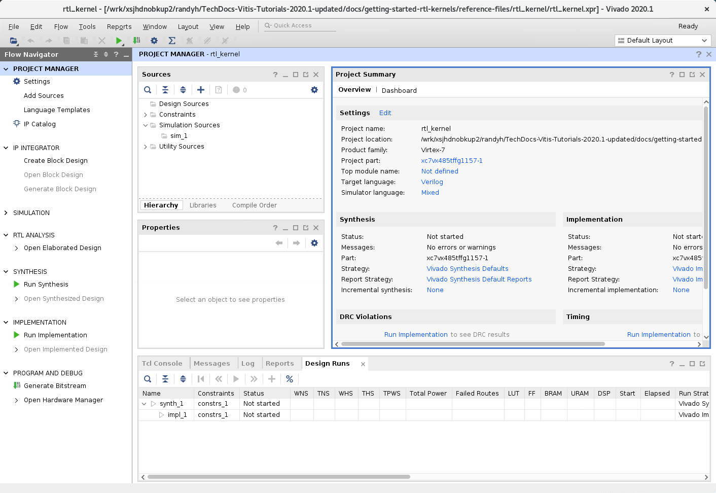
The Vivado IDE opens with the new project.
Add Kernel Sources
You are ready to add RTL files into the project to package as an IP. The RTL files have been provided for you in this tutorial, but this is the point at which you would insert your own RTL code.
In the Sources view, click the Add Sources command (
 ). The Add Sources window is displayed.
Click Add or create design sources, and then click Next.
Click Add Directories, browse to
reference-files/src, and select theIPdirectory (which contains the RTL sources).NOTE: To add your own RTL IP, specify the required folder or files.
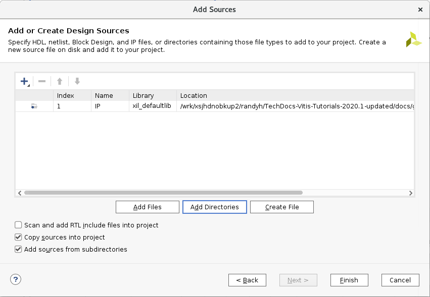
Select the Copy sources into project and Add sources from subdirectories.
Click Finish.
The files are added to the project, and the Vivado Design Suite automatically identifies the
Vadd_A_B.vfile as the top level of the design. This RTL module has an interface which is compatible with the Hardware Interface Requirements for RTL kernels as discussed in the Introduction. This can be seen in theVadd_A_Bmodule definition by double-clicking the file in the Sources view to open it in a Code Editor window.module Vadd_A_B #( parameter integer C_S_AXI_CONTROL_ADDR_WIDTH = 12 , parameter integer C_S_AXI_CONTROL_DATA_WIDTH = 32 , parameter integer C_M00_AXI_ADDR_WIDTH = 64 , parameter integer C_M00_AXI_DATA_WIDTH = 512, parameter integer C_M01_AXI_ADDR_WIDTH = 64 , parameter integer C_M01_AXI_DATA_WIDTH = 512 )
Open the IP Packager
With the files added to your project, you can package the IP for use as a kernel.
To start this process, select Tools > Create and Package New IP.
Click Next.
Select Package your current project, and click Next.
For IP location, take a look at the default location so you can see where your IP will be packaged. The specified location will be needed when running the
package_xocommand in a later step.Click Next. The Create and Package IP summary page is displayed.
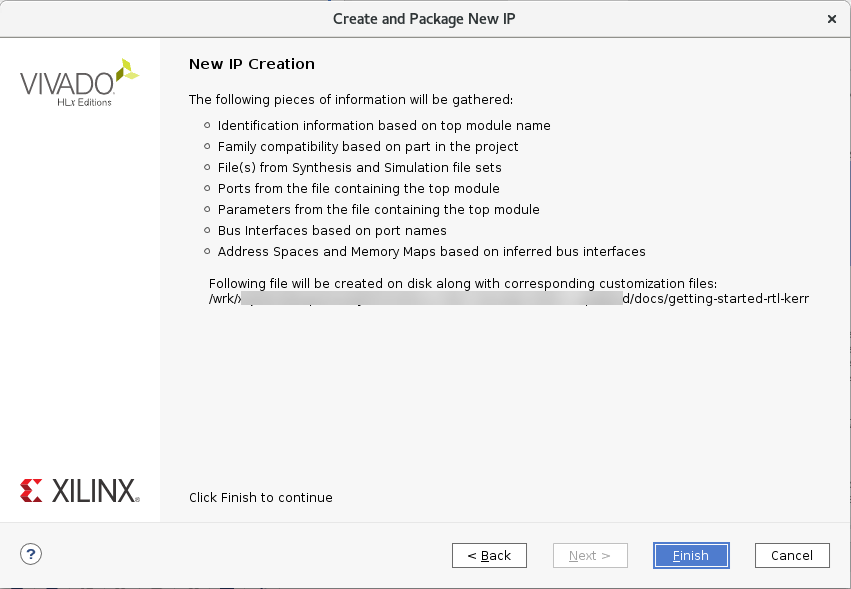
Examine the summary and click Finish to proceed.
The Package IP window is displayed.
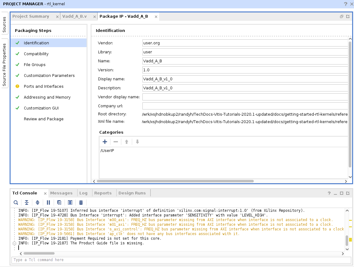
Specify the Control Protocol
Under Packaging Steps, select Compatibility. This lets package the IP as a kernel object (.xo) for use in the Vitis tool flow, and also configures the specific Xilinx parts or device families compatible with your custom IP.
Enable Package for Vitis, and ensure that both Package for IPI and Ignore Freq_Hz are enabled as well.
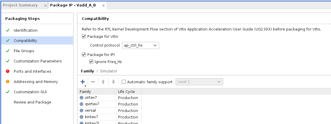
Enabling the Package for Vitis checkbox lets you specify the Control protocol for the RTL kernel. The default is ap_ctrl_hs, but other protocols such as user_managed and ap_ctrl_chain are also suported as described in Software Controllable Kernels.
Leave ap_ctrl_hs selected for this tutorial. The tool sets required properties for the Vitis kernel.
set_property sdx_kernel true [ipx::current_core]
set_property sdx_kernel_type rtl [ipx::current_core]
set_property vitis_drc {ctrl_protocol ap_ctrl_hs} [ipx::current_core]
set_property ipi_drc {ignore_freq_hz true} [ipx::current_core]
Notice that the Ports and Interfaces tab now shows a DRC error because of this setting. The error in this case is that the s_axi_control interface does not have a defined register which you will add shortly.
Edit Ports and Interfaces
Under Packaging Steps, select Ports and Interfaces. This displays the Ports and Interfaces window.
Right-click the
m00_axiinterface and select Associate Clocks.The Associate Clocks dialog box displays the list of available clocks. In this case there is just the
ap_clkinterface to associate with the AXI interface.Select
ap_clkand click OK.Repeat the process to associate
ap_clkwith them01_axiinterface, thes_axi_controlinterface.Click OK to close the Edit Interface dialog box.
Add Control Registers and Address Offsets
You must also add the control registers and address offsets for the interfaces in the design. This can be done through the Addressing and Memory section of the Package IP window. This requires a number of control registers to be added with the following attributes.
| Name | Description | Offset | Size (bits) |
|---|---|---|---|
| CTRL | Control Signals | 0x000 | 32 |
| GIER | Global Interrupt Enable Register | 0x004 | 32 |
| IP_IER | IP Interrupt Enable Register | 0x008 | 32 |
| IP_ISR | IP Interrupt Status Register | 0x00C | 32 |
| scalar00 | Scalar values | 0x010 | 32 |
| A | pointer argument | 0x018 | 64 |
| B | pointer argument | 0x024 | 64 |
Under Packaging Steps, select Addressing and Memory. This displays the Addressing and Memory window.
Under Address Blocks, right-click reg0 and select Add Reg.
Enter the name of the register in the Add Register dialog box, and click OK.
TIP: You will need to add registers for CTRL, GIER, and all the registers listed in the table above. You can also use the following Tcl commands in the Vivado Tcl Console to add the needed registers:
   ipx::add_register CTRL [ipx::get_address_blocks reg0 -of_objects [ipx::get_memory_maps s_axi_control -of_objects [ipx::current_core]]]
   ipx::add_register GIER [ipx::get_address_blocks reg0 -of_objects [ipx::get_memory_maps s_axi_control -of_objects [ipx::current_core]]]
   ipx::add_register IP_IER [ipx::get_address_blocks reg0 -of_objects [ipx::get_memory_maps s_axi_control -of_objects [ipx::current_core]]]
   ipx::add_register IP_ISR [ipx::get_address_blocks reg0 -of_objects [ipx::get_memory_maps s_axi_control -of_objects [ipx::current_core]]]
   ipx::add_register scalar00 [ipx::get_address_blocks reg0 -of_objects [ipx::get_memory_maps s_axi_control -of_objects [ipx::current_core]]]
   ipx::add_register A [ipx::get_address_blocks reg0 -of_objects [ipx::get_memory_maps s_axi_control -of_objects [ipx::current_core]]]
   ipx::add_register B [ipx::get_address_blocks reg0 -of_objects [ipx::get_memory_maps s_axi_control -of_objects [ipx::current_core]]]
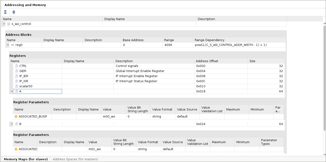
After adding the registers to the Addressing and Memory window (as shown in the following figure), you will need to add the descriptions, offset, and size to the registers.
For each register, click in the Description field of the register and enter the description from the table above.
Click in the Address Offset field and enter the offset.
Click in the Size field and enter the field.
TIP: Description is optional, but Offset and Size are required.
After completing the addition of the various registers and their attributes in accordance with the table above, you must also assign an M_AXI interface to each of the pointer arguments.
Select register
Ain the Registers table, and right-click and select Add Register Parameter.In the Add Register Parameter dialog box, add the ASSOCIATED_BUSIF parameter, and click OK.
This parameter associates the bus interface with the register.Repeat the prior two steps for register
B.In the Value field for ASSOCIATED_BUSIF enter
m00_axifor registerA, andm01_axifor registerB.
Notice that the DRC error on the Ports and Interfaces goes away as you define the registers for the RTL kernel.
Check Integrity, Assign Properties, and Package IP
Under the Packaging Steps, Select Review and Package. This displays the Review and Package window. You are now ready to package the IP. However, first check that an archive file will be generated when packaging the IP. This is the default behavior when Package for Vitis is enabled.
Look in the After Packaging section of the Review and Package window. If you see that an archive will not be generated, then you should enable the archive:
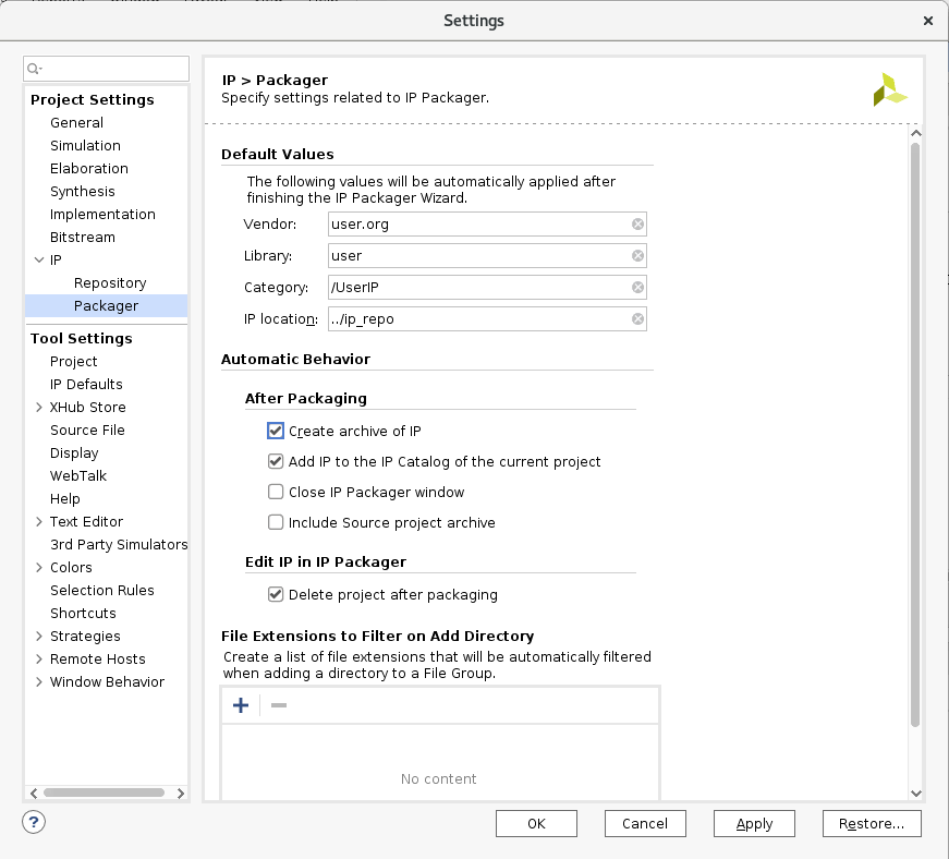
In the Review and Package window, select Edit packaging settings. This displays the Settings dialog box with the IP Package section displayed.
Under the After Packaging section of the dialog box, enable Create archive of IP as shown below, and click OK.
You should see the Review and Package window change to reflect that an archive will now be created.
Click Package IP.
After packaging the IP you should see dialog box indicating that the IP packaged successfully.
With Package for Vitis enabled, the tool automatically runs the package_xo command to create the Vitis kernel (.xo) file. The package_xo command also packages the IP files and the kernel.xml file into the generated .xo file. You can examine the Tcl Console window to see that the package_xo command has been run.
package_xo -force -xo_path <tutorial_path>/rtl_kernel/rtl_kernel.srcs/sources_1/imports/xo/Vadd_A_B.xo -kernel_name Vadd_A_B -ip_directory <tutorial_path>/rtl_kernel/rtl_kernel.srcs/sources_1/imports/IP -ctrl_protocol ap_ctrl_hs
Where:
package_xo: Command name to create a compiled object file (.xo) from the Vivado IP.
-force: overwrites existing kernel file if one exists.
-xo_path: Path and name of the xo file
-kernel_name: Name of the kernel to create, and should match the RTL module name.
-ip_directory: Path to look for the packaged Vivado IP.
-ctrl_protocol: Specifies the control protocol the kernel implements. This can be one of the supported control protocols, but in this tutorial it must be ap_ctrl_hs.
TIP: The
package_xocommand also has a -kernel_xmloption to specify an existingkernel.xmlfile if desired.
After the
package_xocommand returns, navigate to thereference-files/rtl_kernel/rtl_kernel.srcs/sources_1/importsfolder and look at theVadd_A_B.xofile. You can use this file in Vitis application acceleration flow as explained later in this tutorial.
Next Steps
Next, you will work through the RTL Kernel Wizard Flow flow. This recreates the Vitis kernel (.xo) file you just created, but you will use an alternative approach.
Return to Main Page — Return to Start of this Tutorial
Copyright© 2020 Xilinx