Table of Contents
1-Dimensional(Line) FFT L1 FPGA Module
Overview
Vitis DSP Library offers a fully synthesizable Super Sample data Rate (SSR) FFT with a systolic architecture to process multiple input samples every clock cycle. The number of samples processed in parallel per cycle is denoted by the SSR factor. The FFT is implemented as a C++ template function that synthesizes into a streaming architecture. The FFT architecture used for implementation can be parametrized through template parameters, which are grouped in a C++ struct of type ssr_fft_default_params. A new structure can be defined by extending the default structure and re-defining required member constants as follows:
struct ssr_fft_fix_params:ssr_fft_default_params
{
        static const int N = 1024;
        static const int R = 4;
        static const scaling_mode_enum scaling_mode = SSR_FFT_NO_SCALING;
        static const fft_output_order_enum output_data_order = SSR_FFT_NATURAL;
        static const int twiddle_table_word_length = 18;
        static const int twiddle_table_integer_part_length = 2;
        static const transform_direction_enum transform_direction = FORWARD_TRANSFORM;
        static const butterfly_rnd_mode_enum butterfly_rnd_mode = TRN;
};
The structure above defines:
- N: Size or length of transform
- R: The number of samples to be processed in parallel SSR Factor and radix of FFT algorithm used
- scaling_mode: The scaling mode as enumeration type (FFT has three different scaling modes)
- output_data_order: Which will decided if data will be in natural order or digit reversed transposed order
- twiddle_table_word_length: Defines total number of bits to be used for storing twiddle table factors
- twiddle_table_integer_part_length: The number of integer bits used for storing integer part of twiddles
- transform_direction : Defines of the direction of transform, inverse transform (IFFT) or forward transform (FFT)
- butterfly_rnd_mode : Defines the rounding mode used by butterflies in FFT stages
xf::dsp::fft::fft<fftParams><ssr_fft_fix_params>(...);
Multi-Instance Support
The current release of Vitis FFT supports the use of multiple instances of 1-D SSR FFT in a single design. To enable the use of multiple instances, the fft function takes as an input a new template parameter besides the parameter structure. This parameter gets a default value if user doesn’t provide any value for it. But if multiple instance support is required all the instances used should be provided with the unique integer template parameter.
xf::dsp::fft::fft<fftParams,1><ssr_fft_fix_params>(...);
xf::dsp::fft::fft<fftParams,2><ssr_fft_fix_params>(...);
Data Type Support for Synthesis
Currently 1-D SSR FFT supports fixed point and floating point complex inputs for synthesis.
Fixed Point
The fixed point FFT implementation is based on fixed point data types std::complex<ap_fixed<>> which are used for synthesis and implementation. It is possible to use floating point types std::complex<float> and std::complex<double> for simulation but these floating point complex models are not synthesizable. For the best results with fixed point type, limit the data bit width to 27 bits (integer + fraction) as it helps to map multiplication and addition within FFT butterflies directly onto a single DSP block. Larger inputs can be used but may lead to slower Fmax and more resource utilization. Finally, note that the complex exponential/twiddle factor storage is on 18 bits (16F+2I bits). The selection of 18-bit is made keeping in view the 18x27 multipliers available within DSP blocks on Xilinx FPGAs.
Floating Point
1-D SSR FFT also supports synthesis for single precision floating point type. It may be synthesized for double precision but this has not been tested. For synthesizing a complex floating point type, it is required that std::complex type not to be used as a complex wrapper. Since this wrapper has some issues and it is required that a wrapper class provided with the VitisDSP library called complex_wrapper<…> is used for wrapping complex float numbers. Also while synthesizing floating point 1-D SSR FFT the parameters in the structure which carry information such as scaling mode, twiddle factor storage bits, butterfly rounding mode etc. which are only related to fixed point data-path, carry no meaning. Instead FFT parameter structure can simply define relevant parameters as shown below:
struct ssr_fft_fix_params:ssr_fft_default_params
{
        static const int N = 1024;
        static const int R = 4;
        static const fft_output_order_enum output_data_order = SSR_FFT_NATURAL;
        static const transform_direction_enum transform_direction = FORWARD_TRANSFORM;
};
Managing Bit Growth in FFT Stages
The bit growth management is required for fixed point implementation only. The FFT supports three different modes to manage bit growth between FFT stages. These three modes can be used to allow bit growth in every stage, or use scaling in every stage without any bit growth, or allow bit growth until 27 bits and then start using scaling. The detailed description for the different modes are as follows:
SSR_FFT_GROW_TO_MAX_WIDTH
When the scaling_mode constant in the parameter structure is set to SSR_FFT_GROW_TO_MAX_WIDTH, it specifies growth from stage to stage, starting from the first stage to a specified max bit width. The output bit width grows until 27 bits and then saturates. The output bit width grows by log2(R) bits in every stage, and then maxes outs at 27 bits to keep the butterfly operation mapping to DSPs. This option is useful when the initial input bit width is less than 27 bits.
SSR_FFT_SCALE
When the scaling_mode constant in the parameter structure is set to SSR_FFT_SCALE, it enables scaling of outputs in every stage. The output is scaled in every stage and loses precision. An FFT with size L and Radix=SSR=R has logR(L) stages. This option is useful when the input bit width is already close to 27 bits and it is required that the output does not grow beyond 27 bits so that multiplication can be mapped to DSPs.
SSR_FFT_NO_SCALE
When the scaling_mode constant in the parameter structure is set to SSR_FFT_NO_SCALE, the bit growth is allowed in every stage and the output grows unbounded by log2(R) in every stage. This setting can be useful when high precision is required. However, if the output bit width grows beyond 27 bits, the multiplication may not map to only DSPs, but also start using FPGA fabric logic in combination. This may reduce the clock speed and increase resource utilization.
Configurations for Fixed Point Implementation (Recommended Flow)
1-D SSR FFT supports multiple scaling modes and provides options to define input bit-widths and bit-width required to store exponential values (sin/cos in look-up tables). The signal to noise ratio that defines the quality of the output signal depends on the choice of these different parameters and also on the quantification scheme used for converting real valued continuous signal or float point signal to fixed point. The range and the resolution of the signal, essentially the integer bits and the fraction bits, should be selected carefully to have good signal-to-noise ratio (SNR) at the output of the FFT. Following is the recommended flow for working with 1-D SSR FFT HLS IP for fixed point implementation.
Start With Floating Point Model
Currently, 1-D SSR FFT can be used with ap_fxied<>, float, and double types. The following table list the support for synthesis and simulation.
| Type | Synthesis | Simulation |
|---|---|---|
| std::complex <ap_fixed <>> | YES | YES |
| std::complex<float> | NO | YES |
| std::complex<double> | NO | YES |
| complex_wrapper<double> | NO | YES |
| complex_wrapper<float> | YES | YES |
The recommended starting point is to start with float/double inner type in std::complex<> and verify the SNR against a reference model, such as the Matlab/Python/Octave/Simulink whichever modeling language or tool is used by generating golden test vectors. The synthesizable version of the 1-D SSR FFT currently supports ap_fixed<> and float as inner type, so the next step in case of fixed point implementation is to start experimenting with a fixed point model.
Fixed Point Modeling and Implementation
Fixed Point Model
Once working with the fixed point model, the recommended scaling mode to start with is SSR_FFT_NO_SCALING. The input bit-widths should be selected as follows. Create an initial fixed point model with type ap_fixed<WL, IL>. The overall input type is std::complex <ap_fixed<WL, IL>, essentially storing the real and imaginary parts of the input. These parts are:
- IL: Integer bits, selected based on the input range
- WL: Word Length= IL + FL, where FL is the Fraction Bit Width, selected based on input resolution
In this case, 1-D SSR FFT internally does not use any scaling because of scaling mode selection. Therefore, no potential scaling errors will be seen at the output. With scaling mode set to no scaling, you can experiment with other fixed point parameters such as integer bits and fraction bits used to represent the input samples. The simplistic approach would be to select bits required to represent the input based on the input range and resolution but depending on the other input characteristic user can optimize these bit widths.
Selecting Bit Widths for Inputs
The selection of input bit width depends on the input data characteristics and the required resolution, and is a data-dependent choice essentially depending on range and resolution of the test data. For simulation purposes, you can select an arbitrarily large number of bits for representing integer and fraction bits. For implementation, you must make an optimal choice keeping in mind the required SNR. The recommended strategy is to do the following:
- Keep the scaling mode fixed to SSR_FFT_NO_SCALING
- Change the input bits for integer and fraction representation by observing the signal to noise ratio at the output of 1-D SSR FFT
- Reduce the bit widths such that the output SNR requirement is met by the minimum required bits
Once the SNR requirements are met, you can proceed to other fixed point optimizations, such as bits required to store complex exponential tables and 1-D SSR FFT output scaling options.
Twiddle Factor or Sine/Cosine Lookup Table Quantization
You can change the number of bits used to quantize the sin/cos table (twiddle factors/complex exponential). The recommended setting is total 18 bits and 2 bits for the fraction. This setting ensures that during multiplication, the twiddle/sin/cos input can map to the 18-bit input of the DSP block in Xilinx® FPGAs. The model can synthesize and work for other large bit widths, but performance might be worse due to multiplication operations not mapping to a single DSP block and being implemented using multiple DSP blocks and/or FPGA fabric. The twiddle factor width reduction can be useful when the initial setting for twiddle factor storage is larger than 18 bits. By default, it is set to use 18 bits with 2 bits reserved for the signed integer part. The 2 bits are essentially needed to accurately represent a range of numbers from +1 to -1 (for sin/cos) in the table.
Choosing the Best Scaling Mode
After the choice for input bit width and twiddle factors is made with no scaling, which gives acceptable SNR or root mean square (RMS) error at the output of fixed point 1-D SSR FFT, you can start to experiment with the choice of scaling modes. Three different scaling modes are available with 1-D SSR FFT. The recommended strategy is to start with SSR_FFT_NO_SCALING. If there is an acceptable SNR/RMS error at the output, switch to SSR_FFT_GROW_TO_MAX_WIDTH. If there is still an acceptable SNR/RMS error, switch to SSR_FFT_SCALE and observe the SNR/RMS again if it is acceptable keep using SSR_FFT_SCALE otherwise revert back to another mode which gives acceptable SNR/RMS error at the output.
SSR_FFT_NO_SCALING
This is the recommended mode to start with. It performs no scaling but the output bit width grows in every stage by log2(R=SSR). For example, if the size of FFT is N=64 and SSR=R=4 is selected, then 1-D SSR FFT has log4 (64) = 3 stages. If the input bit width is W, the output bit width is W+3*2=W+6. Therefore, the output would have grown by logR(N)*log2(R) bits. SSR_FFT_NO_SCALING preserves the accuracy of the computation, but at maximum hardware cost. The 1-D SSR FFT computation is done in stages with one stage feeding the next stage, so essentially it is a pipeline of stages. One of the downfalls of uncontrolled bit growth is that at some point, in a certain stage when output widths of one stage increase beyond a limit where multiplication operation cannot map to DSP blocks on the FPGA, the design performance in terms of speed may fall considerably. For example, for a given design with logR(N) * log2(R) + Input Bit Width(IL+FL) > max(DSP Block Multiplier Inputs), you might consider using one of the other two available scaling schemes. For Xilinx DSP48 blocks with 18x27 multipliers, the condition will be logR(N) * log2(R) + Input Bit Width > 27.
SSR_FFT_GROW_TO_MAX_WIDTH
In this mode, a hybrid approach is used. Initially the bit growth is allowed if there is any room for growth. If in the starting FFT stages, the output bit-widths are smaller than what can be mapped to DSP blocks, it allows the bit growth. When the bit width grows beyond what can be mapped to DSP blocks, it will start scaling the output.
SSR_FFT_SCALE
When you know that for a given 1-D FFT size N and SSR factor, the output will grow beyond a limit which DSP multiplier blocks cannot handle on a given FPGA device, you have the option to set the scaling on for every stage by selecting the SSR_FFT_SCALE option. This option scales the output in every stage by right shifting the output by log2 (SSR=R) in every stage. The recommended flow only provides a guideline for creating a fixed point model and discusses options available for it in 1-D SSR FFT. Depending on the design SNR/RMS requirements the user is required to carefully select all these parameters keeping in view different performance and SNR/RMS requirements for given application.
1-D SSR FFT Library Usage
Following sections describe how to use FFT from Vitis DSP Library.
Fixed Point 1-D SSR FFT Usage
The Vitis 1-D FFT L1 module can be used in a C++ HLS design by: 1- cloning the Vitis DSP Library git repository and add the following path to compiler include path:
REPO_PATH/dsp/L1/include/hw/vitis_fft/fixed/
2- Include vt_fft.hpp
3- Use namespace xf::dsp::fft
4- Define fft parameter structure say call it params_fix by extending ssr_fft_default_params like Defining 1-D FFT Parameter Structure
5- call fft<params_fix>(input_array,output_array)
The following section gives usage examples and explains some other interface level details for use in C++ based HLS design. To use the 1-D SSR FFT L1 module:
- Include the
vt_fft.hppheader:
#include "vt_fft.hpp"
- Use namespace
xf::dsp::fft
using namespace xf::dsp::fft;
- Define a C++ structure that extends
ssr_fft_default_params:
struct params_fix:ssr_fft_default_params
{
        static const int N-SSR_FFT_L;
        static const int R=SSR_FFT_R;
        static const scaling_mode_enum
        scaling_mode=SSR_FFT_GROW_TO_MAX_WIDTH;
        static const fft_output_order_enum
        output_data_order=SSR_FFT_NATURAL;
        static const int twiddle_table_word_length=18;
        static const int twiddle_table_intger_part_length=2;
};
- Call 1-D SSR FFT as follows:
fft<params_fix>(inD,outD);
//OR
fft<params_fix,IID>(inD,outD);
// IID: is a constant giving instance ID
where inD and outD are 2-dimensional complex arrays of ap_fixed, float or double type, synthesis and simulation use is already explained in the previous table. The I/O arrays can be declared as follows:
Fixed Point Type First define input type, then using type traits calculate output type based on ssr_fft_params struct (output type calculation takes in consideration scaling mode based bit-growth and input bit-widths).
Floating Point 1-D SSR FFT Usage
The Vitis 1-D FFT L1 module can be used in a C++ HLS design by:
1- Cloning the Vitis DSP Library git repository and add the following path to compiler include path:
REPO_PATH/dsp/L1/include/hw/vitis_fft/float/
2- Include vt_fft.hpp
3- Use namespace xf::dsp::fft
4- Define fft parameter structure lets say call it params_float by extending ssr_fft_default_params like Defining 1-D FFT Parameter Structure
5- call fft<params_float>(input_array,output_array)
The following section gives usage examples and explains some other interface level details for use in C++ based HLS design. To use the 1-D SSR FFT L1 module:
- Include the
vt_fft.hppheader:
#include "vt_fft.hpp"
- Use namespace
xf::dsp::fft
using namespace xf::dsp::fft;
- Define a C++ structure that extends ssr_fft_default_params:
struct params_float:ssr_fft_default_params
{
   static const int N = 1024;
   static const int R = 4;
   static const fft_output_order_enum output_data_order = SSR_FFT_NATURAL;
   static const transform_direction_enum transform_direction = FORWARD_TRANSFORM;
};
- Call 1-D SSR FFT as follows:
fft<params_float>(inD,outD);
//OR
fft<ssr_fft_params,IID>(inD,outD);
// IID: is a constant giving instance ID
where inD and outD are 2-dimensional complex arrays of ap_fixed, float or double type, synthesis and simulation use is already explained in the previous table. The I/O arrays can be declared as follows:
Fixed Point Type First define input type, then using type traits calculate output type based on ssr_fft_params struct (output type calculation takes into consideration scaling mode based bit-growth and input bit-widths not relevant for type float).
typedef std::complex< float > I_TYPE;
typedef xf::dsp::fft::ssr_fft_output_type<ssr_fft_params,I_TYPE>::t_ssr_fft_out O_TYPE;
I_TYPE inD[SSR_FFT_R][SSR_FFT_L/SSR_FFT_R];
O_TYPE outD [R][L/R];
Here SSR_FFT_R defines SSR factor and SSR_FFT_L defines the size of the FFT transform.
Float/Double Type: First define the double/float input type, then using type traits calculate output type based on ssr_fft_params struct. For float types the output type calculation will return the same type as input.
typedef std::complex< float/double > I_TYPE;
typedef hls::ssr_fft::ssr_fft_output_type<ssr_fft_params,I_TYPE>::t_ssr_fft_out O_TYPE;
I_TYPE inD[SSR_FFT_R][SSR_FFT_L/SSR_FFT_R];
O_TYPE outD[SSR_FFT_R][SSR_FFT_L/SSR_FFT_R];
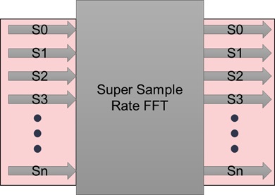
1-D SSR FFT Input Array Reading and Writing Considerations
After synthesis, 1-D SSR FFT HLS IP maps to a streaming block with FIFO interface at both the input and output, as shown in the following figure:
During synthesis, HLS pragmas placed inside IP description will map the 2-dimensions inside the I/O arrays to time and a wide-stream. It uses the HLS STREAM pragma for the second dimension. For the first dimension, it uses pragmas for data packing, partitioning and reshaping to create a single wide stream. If input and output arrays are declared as the following:
I_TYPE inD[R][L/R];
O_TYPE outD[R][L/R];
The dimensions with size L/R will be mapped to time and dimension with size R mapped to one stream which is R-wide. This mapping places some constraints on how these arrays can be read and written to by consumers and producers while writing C++ design using 1-D SSR FFT. These constraints stem from the physical mapping of array dimensions to time and parallel wide-accesses. The read and write on 1-D SSR FFT I/O arrays can be performed as follows:
1. The input should be written in a nested loop as follows, with loop accessing the first dimension to be the inner loop. The outer loop should access the time/2nd dimension:
for( int t=0;t<L/R;t++)
{
        for (int r=0; r <R : r++)
        {
        inD[r][t] = …… ;
        }
}
- The output should be read in a similar fashion as follows:
for( int t=0;t<L/R;t++)
{
        for (int r=0; r <R : r++)
        {
        ….. = outD[r][t] ;
        }
}
3. If the 1-D SSR FFT IP is facing another HLS IP in the input chain or output chain, the inner loop doing reading and writing should be unrolled.
1-D SSR FFT Usage in Dataflow Region, Streaming/Non-Streaming Connections
1-D SSR FFT internally relies heavily on HLS dataflow optimization. The potential use case for 1-D SSR FFT could interconnect with an FFT input or output in two ways:
- Streaming Connection
- Non-Streaming Connections
Streaming Connection
In the case of a streaming connection at the input, the scenario should look as follows:
#pragma HLS DATAFLOW
in_dummy_proc (..., fft_in);
fft<ssr_fft_params>(fft_in, fft_out);
out_dummy_proc(fft_out, ....)
...
...
...
The constraint for input producer is that it should produce a wide stream. The constraint for output consumers is that it should consume a wide stream. These constraints are also described in previous sections.
Non-Streaming Connection
The current version of the 1-D SSR FFT does not support non-streaming connection at the output and input. However, it can be enabled by placing adapters at the input/output as required, which can convert stream to different interfaces. For example, the following code snippet is an input adapter that maps streaming interface to memory based interface:
template < type name TYPE, int R, int L >
void fft_input_adapter (TYPE inData[R][L/R], TYPE outDataStream[R][L/R])
{
        #pragma HLS INLINE off
        #pragma HLS DATA_PACK variable=inData
        #pragma HLS ARRAY_RESHAPE variable=inData complete dim=1
        for(int t=0; t<L/R; t++)
        {
                #pragma HLS PIPELINE II=1
                for (int r = 0; r< R; ++r)
                {
                outDataStream [r][t] = inData[r][t];
                }
        }
}

.
.
.

// Usage of Adapter at input side:
#pragma HLS DATAFLOW
in_proc_memory_based(...,in_data_mem_based)
fft_input_adapter<TYPE_NAME,R,L>(in_data_mem_based,fft_in_stream_based);
hls:ssr_fft::fft<ssr_fft_params>(fft_in_stream_based,fft_out_strema_based);
out_dummy_proc(fft_out_stream_based, ....)
...
...
...
Note: The adapter for the output side can be constructed using a similar method.
1-D FFT Examples
The following sections provides brief details of examples provided for 1-D Super Sample Rate FFT.
1-D Fixed Point FFT Example
The example below follows the sequence of steps described in previous sections to do a transform on impulse signal. The listing give below data_path.hpp describes the datapath, by defining size,SSR, data-path bit-widths, scaling mode, out order etc. It also includes top level library interfce header vt_fft.hpp which gives to fft function defined in namespace xf::dsp::fft
#ifndef _DATA_PATH_H_
#define _DATA_PATH_H_
#include <ap_fixed.h>
#include <complex>
#include "vt_fft.hpp"
using namespace xf::dsp::fft;

// Define FFT Size and Super Sample Rate
#define FFT_LEN 16
#define SSR 4
// Define fixed point input/output bit-widths
#define IN_WL 16
#define IN_IL 2
#define TW_WL 16
#define TW_IL 2

//Define FFT instane ID, every instance created should have unique ID
#define IID 0

typedef std::complex<ap_fixed<IN_WL, IN_IL> > T_in;

/* Define parameter structure for FFT that defines
 * holds , size, SSR, scaling mode, output order sin/cos
 * bit resoulation for storage*/
struct fftParams : ssr_fft_default_params {
    static const int N = FFT_LEN;
    static const int R = SSR;
    static const scaling_mode_enum scaling_mode = SSR_FFT_NO_SCALING;
    static const fft_output_order_enum output_data_order = SSR_FFT_NATURAL;
    static const int twiddle_table_word_length = TW_WL;
    static const int twiddle_table_intger_part_length = TW_IL;
};
// Using type traits calculate the output type given FFT param struct
// and the input type
typedef ssr_fft_output_type<fftParams, T_in>::t_ssr_fft_out T_out;

#endif // _DATA_PATH_H_
The listing top_module.hpp and top_module.cpp declare and define top level module. The top level function here is very simple it only wraps the core SSR FFT function call in a top level wrapper called fft_top
#include "data_path.hpp"
#include <hls_stream.h>

void fft_top(T_in p_inData[SSR][FFT_LEN / SSR], T_out p_outData[SSR][FFT_LEN / SSR]);
#include "top_module.hpp"
#include "data_path.hpp"
void fft_top(T_in p_inData[SSR][FFT_LEN / SSR], T_out p_outData[SSR][FFT_LEN / SSR]) {
    xf::dsp::fft::fft<fftParams, IID>(p_inData, p_outData);
}
The listing below gives main funtion that generates impulse data for FFT input in a 2-dimensional array which is SSRx(Size/SRR) and feeds it to top level which produces a 2-dimensional output array of same dimensions. The impulse input produces a step which is verified and test declared as passed.
#include "top_module.hpp"
#include <iostream>

int main(int argc, char** argv) {
    T_in inData[SSR][FFT_LEN / SSR];
    T_out outData[SSR][FFT_LEN / SSR];
    for (int r = 0; r < SSR; ++r) {
        for (int t = 0; t < FFT_LEN / SSR; ++t) {
            if (r == 0 && t == 0)
                inData[r][t] = 1;
            else
                inData[r][t] = 0;
        }
    }
    for (int t = 0; t < 4; ++t) {
        // Added Dummy loop iterations
        // to make II measurable in cosim
        fft_top(inData, outData);
    }
    int errs = 0;
    for (int r = 0; r < SSR; ++r) {
        for (int t = 0; t < FFT_LEN / SSR; ++t) {
            if (outData[r][t].real() != 1 || outData[r][t].imag() != 0) errs++;
        }
    }
    std::cout << "===============================================================" << std::endl;
    std::cout << "--Input Impulse:" << std::endl;
    for (int r = 0; r < SSR; ++r) {
        for (int t = 0; t < FFT_LEN / SSR; ++t) {
            std::cout << inData[r][t] << std::endl;
        }
    }
    std::cout << "===============================================================" << std::endl;

    std::cout << "===============================================================" << std::endl;
    std::cout << "--Output Step fuction:" << std::endl;
    for (int r = 0; r < SSR; ++r) {
        for (int t = 0; t < FFT_LEN / SSR; ++t) {
            std::cout << outData[r][t] << std::endl;
        }
    }
    std::cout << "===============================================================" << std::endl;

    return errs;
}
Compiling and Building Example HLS Project
Before compiling and running the example it is required to setup the path to HLS compiler which can be done as follows: change the setting of environment variable TA_PATH to point to the installation path of your Vitis 2019.2, and run following command to set up the environment.
export XILINX_VITIS=${TA_PATH}/Vitis/2019.2
export XILINX_VIVADO=${TA_PATH}/Vivado/2019.2
source ${XILINX_VIVADO}/settings64.sh
The example discussed above is also provided as an example and available at the following path : REPO_PATH/dsp/L1/examples/1Dfix_impluse it can be simulated, synthesized or co-simulated as follows:
Simply go to the directory REPO_PATH/dsp/L1/examples/1Dfix_impluse and simulat,build and co-simulate project using : make run XPART='xcu200-fsgd2104-2-e' CSIM=1 CSYNTH=1 COSIM=1 you can choose the part number as required and by settting CSIM/CSYNTH/COSIM=0 choose what to build and run with make target
1-D Floating Point FFT Example
The use of floating point SSR FFT is very similar to fixed point FFT the following listing data_path.hpp gives parameter struct
which is simple as compared to fixed point since data-path constants scaling type, input bit-widths etc are not required for floatig point case. It essentially requires declaration of Size and SSR factor and outptu data order by default is set to natural order, if required it can be changed to digital reversed transposed.
#ifndef _DATA_PATH_H_
#define _DATA_PATH_H_

#include <ap_fixed.h>
#include <complex>
#include "vt_fft.hpp"
using namespace xf::dsp::fft;

// Define FFT Size and Super Sample Rate
#define FFT_LEN 16
#define SSR 4

typedef complex_wrapper<float> T_in;
#define IID 0

// Define parameter structure for FFT
struct fftParams : ssr_fft_default_params {
    static const int N = FFT_LEN;
    static const int R = SSR;
};

// typedef ssr_fft_output_type<fftParams,T_in>::t_ssr_fft_out T_out;
typedef T_in T_out;

#endif // _DATA_PATH_H_
The following two listings top_moduel.hpp and top_module.cpp give top level module decleration and definition only.
#include "data_path.hpp"
#include <hls_stream.h>

void fft_top(T_in p_inData[SSR][FFT_LEN / SSR], T_out p_outData[SSR][FFT_LEN / SSR]);
#include "top_module.hpp"
#include "data_path.hpp"
void fft_top(T_in p_inData[SSR][FFT_LEN / SSR], T_out p_outData[SSR][FFT_LEN / SSR]) {
xf::dsp::fft::fft<fftParams, IID>(p_inData, p_outData);
The listing below main.cpp gives main function which creates and impulse input and verfies if the correct output is produced. The only significant change w.r.t to fixed point is the data type declaration and the param struct otherwise this example is very the same like the use of fixed point FFT.
#include "top_module.hpp"
#include <iostream>
int main(int argc, char** argv) {
    T_in inData[SSR][FFT_LEN / SSR];
    T_out outData[SSR][FFT_LEN / SSR];
    for (int r = 0; r < SSR; ++r) {
        for (int t = 0; t < FFT_LEN / SSR; ++t) {
            if (r == 0 && t == 0)
                inData[r][t] = 1;
            else
                inData[r][t] = 0;
        }
    }
    for (int t = 0; t < 4; ++t) {
        // Added Dummy loop iterations
        // to make II measurable in cosim
        fft_top(inData, outData);
    }
    int errs = 0;
    for (int r = 0; r < SSR; ++r) {
        for (int t = 0; t < FFT_LEN / SSR; ++t) {
            if (outData[r][t].real() != 1 || outData[r][t].imag() != 0) errs++;
        }
    }
    std::cout << "===============================================================" << std::endl;
    std::cout << "--Input Impulse:" << std::endl;
    for (int r = 0; r < SSR; ++r) {
        for (int t = 0; t < FFT_LEN / SSR; ++t) {
            std::cout << inData[r][t] << std::endl;
        }
    }
    std::cout << "===============================================================" << std::endl;

    std::cout << "===============================================================" << std::endl;
    std::cout << "--Output Step fuction:" << std::endl;
    for (int r = 0; r < SSR; ++r) {
        for (int t = 0; t < FFT_LEN / SSR; ++t) {
            std::cout << outData[r][t] << std::endl;
        }
    }
    std::cout << "===============================================================" << std::endl;

    return errs;
}
Compiling and Building Example HLS Project
Before compiling and running the example it is required to setup the path to HLS compiler which can be done as follows: change the setting of environment variable TA_PATH to point to the installation path of your Vitis 2019.2, and run following command to set up the environment.
export XILINX_VITIS=${TA_PATH}/Vitis/2019.2
export XILINX_VIVADO=${TA_PATH}/Vivado/2019.2
source ${XILINX_VIVADO}/settings64.sh
The example discussed above is also provided as an example and available at the following path : REPO_PATH/dsp/L1/examples/1Dfloat_impluse it can be simulated, synthesized or co-simulated as follows:
Simply go to the directory REPO_PATH/dsp/L1/examples/1Dfloat_impluse and simulat,build and co-simulate project using : make run XPART='xcu200-fsgd2104-2-e' CSIM=1 CSYNTH=1 COSIM=1 you can choose the part number as required and by settting CSIM/CSYNTH/COSIM=0 choose what to build and run with make target
1-D FFT Tests
Different tests are provided for fixed point and floating point 1-D FFT. These test can be ran indivisually using the makefile or they can all be lauched at the same time by using a provided script. All the 1-D FFT tests are in folder REPO_PATH/dsp/L1/tests/hw/1dfft
Launching an Individual Test
- To launch an individual test first it is required to setup environment for lanching Vitis HLS Compiler which can be done as follows:
- setup of environment variable TA_PATH to point to the installation path of your Vitis 2019.2, and run following commands to set up the environment.
export XILINX_VITIS=${TA_PATH}/Vitis/2019.2
export XILINX_VIVADO=${TA_PATH}/Vivado/2019.2
source ${XILINX_VIVADO}/settings64.sh
Once the environment settings are done an idividual test can be launched by going to test folder ( any folder inside sub-directory at any level of REPO_PATH/dsp/L1/test/hw/1dfft that has Makefile is a test) and running the make command :
make run XPART='xcu200-fsgd2104-2-e' CSIM=1 CSYNTH=1 COSIM=1 you can choose the part number as required and by settting CSIM/CSYNTH/COSIM=0 choose what to build and run with make target
Launching all the Tests Collectivey
Scripts are provided in REPO_PATH/dsp/L1/test/ to find and launch all the test inside the repo. These scripts will try to find all the tests with this test folder and launh them one by one and print the summary of tests passed. To launch this script first create a file called set_env.sh that setup up Vitis HLS compiler paths and should look something like this:
export TA_PATH="LOCAL VITIS INSTALL PATH"
export XILINX_VITIS=${TA_PATH}/Vitis/2019.2
export XILINX_VIVADO=${TA_PATH}/Vivado/2019.2
source ${XILINX_VIVADO}/settings64.sh
Once the install paths are setup launch the bash script named “run_all_cosim_tests.sh” to run all the tests.
L1 Performance Benchmarks and QoR
The FFT throughput (initiation interval) can be calculated as L/R where R is the SSR value and L is the number of samples to be transformed. The possible values for R (SSR values) are: 2,4,8,16. These values allow for a Fmax range of 300-550 MHz when targeting the slowest of UltraScale+ speed-grade devices.
1-D Fixed Point FFT
Following table gives the performance of 1-dimensional FFT for 27 bit fixed point complex input. Different SSR factors and FFT sizes are reported for comparison in terms of performance and resource utilization. The synthesis is performed for Alveo U250 FPGA part. From the table it is clear that SSR FFT when synthezied with size upto 4K can run with fmax ranging from 500 to 300 MHz. The results are reported for post place and route. The routing and placement is done using standard Vivado place and route flow no manual floorplanning or routing is done at all.
| Size | SSR | fmax(MHz) | Performance (GSPS) | Performance (2D-FFT/Sec) xMillion | Performance (GOPs) | DSPs | LUT (x1000) | FF (x1000) | BRAM | CP(ns) | II (Cycles) | FPGA/BOARD | Bandwidth (Gbytes/sec) |
|---|---|---|---|---|---|---|---|---|---|---|---|---|---|
| 1024 | 2 | 526 | 1.05 | 1.03 | 52.53 | 36 | 12 | 22 | 14 | 1.9 | 513 | U250 | 8.40 |
| 4096 | 2 | 526 | 1.05 | 0.26 | 63.13 | 44 | 25 | 27 | 34 | 1.9 | 2049 | U250 | 8.42 |
| 1024 | 4 | 513 | 2.04 | 2.00 | 102.17 | 48 | 16 | 24 | 20 | 2.0 | 257 | U250 | 16.35 |
| 4096 | 4 | 518 | 2.07 | 0.51 | 124.23 | 60 | 30 | 29 | 39 | 1.9 | 1025 | U250 | 16.56 |
| 1024 | 8 | 455 | 3.61 | 3.52 | 180.41 | 99 | 32.4 | 52.7 | 34 | 2.2 | 129 | U250 | 28.87 |
| 4096 | 8 | 417 | 3.33 | 0.81 | 199.61 | 104 | 42.6 | 45.5 | 45 | 2.4 | 513 | U250 | 26.61 |
| 1024 | 16 | 370 | 5.83 | 5.70 | 291.74 | 172 | 66 | 85 | 62 | 2.7 | 65 | U250 | 46.68 |
| 4096 | 16 | 298 | 4.74 | 1.16 | 284.60 | 200 | 80 | 74 | 62 | 3.4 | 257 | U250 | 37.95 |
1-D Floating Point (fp32) FFT
Following table gives the performance of 1-dimensional FFT floating point (fp32) complex input under similar setting as used for fixed point 1-D FFT. For floating point types generally the resource usages is larger than fixed point because of larger data-path and need for more complicated compute units for doing operations such as addition, multiplication, comparison etc. The results are reported for post place and route. The routing and placement is done using standard Vivado place and route flow no manual floorplanning or routing is done at all.
| Size | SSR | fmax(MHz) | Performance (GSPS) | Performance (2D-FFT/Sec) xMillion | Performance (GOPs) | DSPs | LUT (x1000) | FF (x1000) | BRAM | CP(ns) | II (Cycles) | FPGA/BOARD | Bandwidth (Gbytes/sec) |
|---|---|---|---|---|---|---|---|---|---|---|---|---|---|
| 1024 | 2 | 500 | 0.998050682 | 0.974658869 | 49.90253411 | 554 | 45.3 | 91.3 | 24 | 2 | 513 | U250 | 7.984405458 |
| 4096 | 2 | 476.1904762 | 0.95191615 | 0.232401404 | 57.11496897 | 670 | 66 | 110 | 50 | 2.1 | 2049 | U250 | 7.615329197 |
| 1024 | 4 | 384.6153846 | 1.532475307 | 1.496557917 | 76.62376534 | 812 | 71.9 | 137.4 | 31 | 2.6 | 257 | U250 | 12.25980245 |
| 4096 | 4 | 366.3003663 | 1.463772 | 0.357366211 | 87.82632002 | 986 | 98 | 166 | 62 | 2.73 | 1025 | U250 | 11.710176 |
| 1024 | 8 | 367.6470588 | 2.918376653 | 2.8499772 | 145.9188326 | 1424 | 129.8 | 247 | 52 | 2.72 | 129 | U250 | 23.34701322 |
| 4096 | 8 | 322.5806452 | 2.575614664 | 0.628812174 | 154.5368798 | 1606 | 158 | 268 | 78 | 3.1 | 513 | U250 | 20.60491731 |
| 1024 | 16 | 192.3076923 | 3.029585799 | 2.958579882 | 151.4792899 | 3072 | 283 | 520 | 91 | 5.2 | 65 | U250 | 24.23668639 |
| 4096 | 16 | 100 | 1.593774319 | 0.389105058 | 95.62645914 | 3664 | 380 | 592 | 46 | 10 | 257 | U250 | 12.75019455 |