Design Examples Using Vitis Vision Library
All the hardware functions in the library have their own respective examples that are available in the github. This section provides details of image processing functions and pipelines implemented using a combination of various functions in Vitis vision. They illustrate how to best implement various functionalities using the capabilities of both the processor and the programmable logic. These examples also illustrate different ways to implement complex dataflow paths. The following examples are described in this section:
- Iterative Pyramidal Dense Optical Flow
- Corner Tracking Using Optical Flow
- Color Detection
- Difference of Gaussian Filter
- Stereo Vision Pipeline
- X + ML Pipeline
- Letterbox
- Image Sensor Processing pipeline
Iterative Pyramidal Dense Optical Flow
The Dense Pyramidal Optical Flow example uses the xf::cv::pyrDown and
xf::cv::densePyrOpticalFlow hardware functions from the Vitis vision
library, to create an image pyramid, iterate over it and compute the
Optical Flow between two input images. The example uses xf::cv::pyrDown function to compute the image pyramids
of the two input images. The two image pyramids are
processed by xf::cv::densePyrOpticalFlow
function, starting from the smallest image size going up to the largest
image size. The output flow vectors of each iteration are fed back to
the hardware kernel as input to the hardware function. The output of the
last iteration on the largest image size is treated as the output of the
dense pyramidal optical flow example.
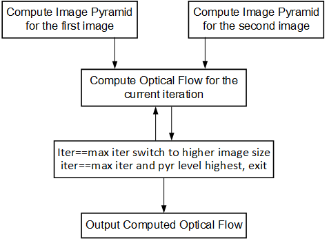
The Iterative Pyramidal Dense Optical Flow is computed in a nested for loop which runs for iterations*pyramid levels number of iterations. The main loop starts from the smallest image size and iterates up to the largest image size. Before the loop iterates in one pyramid level, it sets the current pyramid level’s height and width, in curr_height and current_width variables. In the nested loop, the next_height variable is set to the previous image height if scaling up is necessary, that is, in the first iterations. As divisions are costly and one time divisions can be avoided in hardware, the scale factor is computed in the host and passed as an argument to the hardware kernel. After each pyramid level, in the first iteration, the scale-up flag is set to let the hardware function know that the input flow vectors need to be scaled up to the next higher image size. Scaling up is done using bilinear interpolation in the hardware kernel.
After all the input data is prepared, and the flags are set, the host processor calls the hardware function. Please note that the host function swaps the flow vector inputs and outputs to the hardware function to iteratively solve the optimization problem.
Corner Tracking Using Optical Flow
This example illustrates how to detect and track the characteristic feature points in a set of successive frames of video. A Harris corner detector is used as the feature detector, and a modified version of Lucas Kanade optical flow is used for tracking. The core part of the algorithm takes in current and next frame as the inputs and outputs the list of tracked corners. The current image is the first frame in the set, then corner detection is performed to detect the features to track. The number of frames in which the points need to be tracked is also provided as the input.
Corner tracking example uses five hardware functions from the Vitis vision
library xf::cv::cornerHarris, xf::cv:: cornersImgToList,
xf::cv::cornerUpdate, xf::cv::pyrDown, and xf::cv::densePyrOpticalFlow.
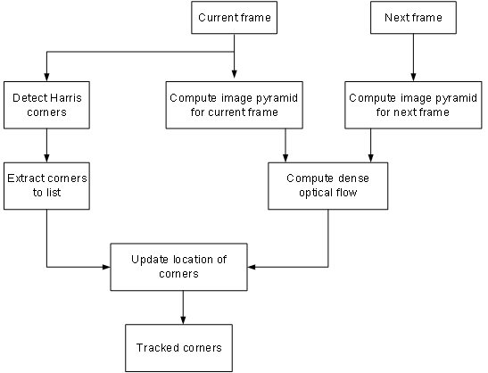
The function, xf::cv::cornerUpdate, has been added to ensure
that the dense flow vectors from the output of
thexf::cv::densePyrOpticalFlow function are sparsely picked and stored
in a new memory location as a sparse array. This was done to ensure that
the next function in the pipeline would not have to surf through the
memory by random accesses. The function takes corners from Harris corner
detector and dense optical flow vectors from the dense pyramidal optical
flow function and outputs the updated corner locations, tracking the
input corners using the dense flow vectors, thereby imitating the sparse
optical flow behavior. This hardware function runs at 300 MHz for 10,000
corners on a 720p image, adding very minimal latency to the pipeline.
cornerUpdate()
API Syntax
template <unsigned int MAXCORNERSNO, unsigned int TYPE, unsigned int ROWS, unsigned int COLS, unsigned int NPC>
void cornerUpdate(ap_uint<64> *list_fix, unsigned int *list, uint32_t nCorners, xf::cv::Mat<TYPE,ROWS,COLS,NPC> &flow_vectors, ap_uint<1> harris_flag)
Parameter Descriptions
The following table describes the template and the function parameters.
| Paramete r | Description |
|---|---|
| MAXCORNE RSNO | Maximum number of corners that the function needs to work on |
| TYPE | Input Pixel Type. Only 8-bit, unsigned, 1 channel is supported (XF_8UC1) |
| ROWS | Maximum height of input and output image (Must be multiple of 8) |
| COLS | Maximum width of input and output image (Must be multiple of 8) |
| NPC | Number of pixels to be processed per cycle. This function supports only XF_NPPC1 or 1-pixel per cycle operations. |
| list_fix | A list of packed fixed point coordinates of the corner locations in 16, 5 (16 integer bits and 5 fractional bits) format. Bits from 20 to 0 represent the column number, while the bits 41 to 21 represent the row number. The rest of the bits are used for flag, this flag is set when the tracked corner is valid. |
| list | A list of packed positive short integer coordinates of the corner locations in unsigned short format. Bits from 15 to 0 represent the column number, while the bits 31 to 16 represent the row number. This list is same as the list output by Harris Corner Detector. |
| nCorners | Number of corners to track |
| flow_vec tors | Packed flow vectors as in xf::cv::DensePyrOpticalFlow function |
| harris_f lag | If set to 1, the function takes input corners from list. if set to 0, the function takes input corners from list_fix. |
The example codeworks on an input video which is read and processed using the Vitis vision library.
cornersImgToList()
API Syntax
template <unsigned int MAXCORNERSNO, unsigned int TYPE, unsigned int ROWS, unsigned int COLS, unsigned int NPC>
void cornersImgToList(xf::cv::Mat<TYPE,ROWS,COLS,NPC> &_src, unsigned int list[MAXCORNERSNO], unsigned int *ncorners)
Parameter Descriptions
The following table describes the function parameters.
| Paramete r | Description |
|---|---|
| _src | The output image of harris corner detector. The size of this xf::cv::Mat object is the size of the input image to Harris corner detector. The value of each pixel is 255 if a corner is present in the location, 0 otherwise. |
| list | A 32 bit memory allocated, the size of MAXCORNERS, to store the corners detected by Harris Detector |
| ncorners | Total number of corners detected by Harris, that is, the number of corners in the list |
Image Processing
The following steps demonstrate the Image Processing procedure in the hardware pipeline
xf::cv::cornerharrisis called to start processing the first input image- The output of
xf::cv::cornerHarrisis fed toxf::cv::cornersImgToList. This function takes in an image with corners (marked as 255 and 0 elsewhere), and converts them to a list of corners. xf::cv::pyrDowncreates the two image pyramids and Dense Optical Flow is computed using the two image pyramids as described in the Iterative Pyramidal Dense Optical Flow example.xf::cv::densePyrOpticalFlowis called with the two image pyramids as inputs.xf::cv::cornerUpdatefunction is called to track the corner locations in the second image. If harris_flag is enabled, thecornerUpdatetracks corners from the output of the list, else it tracks the previously tracked corners.
The HarrisImg() function takes a flag called
harris_flag which is set during the first frame or when the corners need
to be redetected. The xf::cv::cornerUpdate function outputs the updated
corners to the same memory location as the output corners list of
xf::cv::cornerImgToList. This means that when harris_flag is unset, the
corners input to the xf::cv::cornerUpdate are the corners tracked in the
previous cycle, that is, the corners in the first frame of the current
input frames.
After the Dense Optical Flow is computed, if harris_flag is set, the
number of corners that xf::cv::cornerharris has detected and
xf::cv::cornersImgToList has updated is copied to num_corners variable
. The other being the tracked corners list, listfixed. If
harris_flag is set, xf::cv::cornerUpdate tracks the corners in ‘list’
memory location, otherwise it tracks the corners in ‘listfixed’ memory
location.
Color Detection
The Color Detection algorithm is basically used for color object tracking and object detection, based on the color of the object. The color based methods are very useful for object detection and segmentation, when the object and the background have a significant difference in color.
The Color Detection example uses four hardware functions from the Vitis vision library. They are:
- xf::cv::BGR2HSV
- xf::cv::colorthresholding
- xf::cv::erode
- xf::cv::dilate
In the Color Detection example, the color space of the original BGR image is converted into an HSV color space. Because HSV color space is the most suitable color space for color based image segmentation. Later, based on the H (hue), S (saturation) and V (value) values, apply the thresholding operation on the HSV image and return either 255 or 0. After thresholding the image, apply erode (morphological opening) and dilate (morphological opening) functions to reduce unnecessary white patches (noise) in the image. Here, the example uses two hardware instances of erode and dilate functions. The erode followed by dilate and once again applying dilate followed by erode.
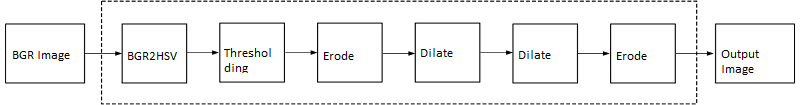
The following example demonstrates the Color Detection algorithm.
    void color_detect(ap_uint<PTR_IN_WIDTH>* img_in,
              unsigned char* low_thresh,
              unsigned char* high_thresh,
              unsigned char* process_shape,
              ap_uint<PTR_OUT_WIDTH>* img_out,
              int rows,
              int cols) {

#pragma HLS INTERFACE m_axi      port=img_in        offset=slave  bundle=gmem0

#pragma HLS INTERFACE m_axi      port=low_thresh    offset=slave  bundle=gmem1
#pragma HLS INTERFACE s_axilite  port=low_thresh
#pragma HLS INTERFACE m_axi      port=high_thresh   offset=slave  bundle=gmem2
#pragma HLS INTERFACE s_axilite  port=high_thresh
#pragma HLS INTERFACE s_axilite  port=rows
#pragma HLS INTERFACE s_axilite  port=cols
#pragma HLS INTERFACE m_axi      port=process_shape offset=slave  bundle=gmem3
#pragma HLS INTERFACE s_axilite  port=process_shape
#pragma HLS INTERFACE m_axi      port=img_out       offset=slave  bundle=gmem4

#pragma HLS INTERFACE s_axilite  port=return

xf::cv::Mat<IN_TYPE, HEIGHT, WIDTH, NPC1> imgInput(rows, cols);
xf::cv::Mat<IN_TYPE, HEIGHT, WIDTH, NPC1> rgb2hsv(rows, cols);
xf::cv::Mat<OUT_TYPE, HEIGHT, WIDTH, NPC1> imgHelper1(rows, cols);
xf::cv::Mat<OUT_TYPE, HEIGHT, WIDTH, NPC1> imgHelper2(rows, cols);
xf::cv::Mat<OUT_TYPE, HEIGHT, WIDTH, NPC1> imgHelper3(rows, cols);
xf::cv::Mat<OUT_TYPE, HEIGHT, WIDTH, NPC1> imgHelper4(rows, cols);
xf::cv::Mat<OUT_TYPE, HEIGHT, WIDTH, NPC1> imgOutput(rows, cols);

// Copy the shape data:
unsigned char _kernel[FILTER_SIZE * FILTER_SIZE];
for (unsigned int i = 0; i < FILTER_SIZE * FILTER_SIZE; ++i) {

    #pragma HLS PIPELINE
    // clang-format on
    _kernel[i] = process_shape[i];
}

#pragma HLS DATAFLOW
// clang-format on
// Retrieve xf::cv::Mat objects from img_in data:
xf::cv::Array2xfMat<PTR_IN_WIDTH, IN_TYPE, HEIGHT, WIDTH, NPC1>(img_in, imgInput);

// Convert RGBA to HSV:
xf::cv::bgr2hsv<IN_TYPE, HEIGHT, WIDTH, NPC1>(imgInput, rgb2hsv);

// Do the color thresholding:
xf::cv::colorthresholding<IN_TYPE, OUT_TYPE, MAXCOLORS, HEIGHT, WIDTH, NPC1>(rgb2hsv, imgHelper1, low_thresh,
                                                                             high_thresh);

// Use erode and dilate to fully mark color areas:
xf::cv::erode<XF_BORDER_CONSTANT, OUT_TYPE, HEIGHT, WIDTH, XF_KERNEL_SHAPE, FILTER_SIZE, FILTER_SIZE, ITERATIONS,
              NPC1>(imgHelper1, imgHelper2, _kernel);
xf::cv::dilate<XF_BORDER_CONSTANT, OUT_TYPE, HEIGHT, WIDTH, XF_KERNEL_SHAPE, FILTER_SIZE, FILTER_SIZE, ITERATIONS,
               NPC1>(imgHelper2, imgHelper3, _kernel);
xf::cv::dilate<XF_BORDER_CONSTANT, OUT_TYPE, HEIGHT, WIDTH, XF_KERNEL_SHAPE, FILTER_SIZE, FILTER_SIZE, ITERATIONS,
               NPC1>(imgHelper3, imgHelper4, _kernel);
xf::cv::erode<XF_BORDER_CONSTANT, OUT_TYPE, HEIGHT, WIDTH, XF_KERNEL_SHAPE, FILTER_SIZE, FILTER_SIZE, ITERATIONS,
              NPC1>(imgHelper4, imgOutput, _kernel);

// Convert _dst xf::cv::Mat object to output array:
xf::cv::xfMat2Array<PTR_OUT_WIDTH, OUT_TYPE, HEIGHT, WIDTH, NPC1>(imgOutput, img_out);

return;

    } // End of kernel
In the given example, the source image is passed to the xf::cv::BGR2HSV
function, the output of that function is passed to the
xf::cv::colorthresholding module, the thresholded image is passed to the
xf::cv::erode function and, the xf::cv::dilate functions and the final
output image are returned.
Difference of Gaussian Filter
The Difference of Gaussian Filter example uses four hardware functions from the Vitis vision library. They are:
- xf::cv::GaussianBlur
- xf::cv::duplicateMat
- xf::cv::subtract
The Difference of Gaussian Filter function can be implemented by applying Gaussian Filter on the original source image, and that Gaussian blurred image is duplicated as two images. The Gaussian blur function is applied to one of the duplicated images, whereas the other one is stored as it is. Later, perform the Subtraction function on, two times Gaussian applied image and one of the duplicated image.
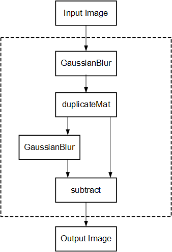
The following example demonstrates the Difference of Gaussian Filter example.
    void gaussiandiference(ap_uint<PTR_WIDTH>* img_in, float sigma, ap_uint<PTR_WIDTH>* img_out, int rows, int cols) {

#pragma HLS INTERFACE m_axi      port=img_in        offset=slave  bundle=gmem0
#pragma HLS INTERFACE m_axi      port=img_out       offset=slave  bundle=gmem1
#pragma HLS INTERFACE s_axilite  port=sigma
    #pragma HLS INTERFACE s_axilite  port=rows
    #pragma HLS INTERFACE s_axilite  port=cols
#pragma HLS INTERFACE s_axilite  port=return


xf::cv::Mat<TYPE, HEIGHT, WIDTH, NPC1> imgInput(rows, cols);
xf::cv::Mat<TYPE, HEIGHT, WIDTH, NPC1> imgin1(rows, cols);
xf::cv::Mat<TYPE, HEIGHT, WIDTH, NPC1> imgin2(rows, cols);
xf::cv::Mat<TYPE, HEIGHT, WIDTH, NPC1, 15360> imgin3(rows, cols);
xf::cv::Mat<TYPE, HEIGHT, WIDTH, NPC1> imgin4(rows, cols);
xf::cv::Mat<TYPE, HEIGHT, WIDTH, NPC1> imgOutput(rows, cols);

#pragma HLS DATAFLOW

// Retrieve xf::cv::Mat objects from img_in data:
xf::cv::Array2xfMat<PTR_WIDTH, TYPE, HEIGHT, WIDTH, NPC1>(img_in, imgInput);

// Run xfOpenCV kernel:
xf::cv::GaussianBlur<FILTER_WIDTH, XF_BORDER_CONSTANT, TYPE, HEIGHT, WIDTH, NPC1>(imgInput, imgin1, sigma);
xf::cv::duplicateMat<TYPE, HEIGHT, WIDTH, NPC1, 15360>(imgin1, imgin2, imgin3);
xf::cv::GaussianBlur<FILTER_WIDTH, XF_BORDER_CONSTANT, TYPE, HEIGHT, WIDTH, NPC1>(imgin2, imgin4, sigma);
xf::cv::subtract<XF_CONVERT_POLICY_SATURATE, TYPE, HEIGHT, WIDTH, NPC1, 15360>(imgin3, imgin4, imgOutput);

// Convert output xf::cv::Mat object to output array:
xf::cv::xfMat2Array<PTR_WIDTH, TYPE, HEIGHT, WIDTH, NPC1>(imgOutput, img_out);

return;
    } // End of kernel
In the given example, the Gaussain Blur function is applied for source image imginput, and resultant image imgin1 is passed to xf::cv::duplicateMat. The imgin2 and imgin3 are the duplicate images of Gaussian applied image. Again gaussian blur is applied to imgin2 and the result is stored in imgin4. Now, perform the subtraction between imgin4 and imgin3, but here imgin3 has to wait up to at least one pixel of imgin4 generation. Finally the subtraction performed on imgin3 and imgin4.
Stereo Vision Pipeline
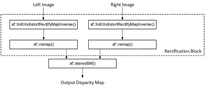
Disparity map generation is one of the first steps in creating a three dimensional map of the environment. The Vitis vision library has components to build an image processing pipeline to compute a disparity map given the camera parameters and inputs from a stereo camera setup.
The two main components involved in the pipeline are stereo
rectification and disparity estimation using local block matching
method. While disparity estimation using local block matching is a
discrete component in Vitis vision, rectification block can be constructed
using xf::cv::InitUndistortRectifyMapInverse() and xf::cv::Remap(). The
dataflow pipeline is shown below. The camera parameters are an
additional input to the pipeline.
The following code is for the pipeline.
    void stereopipeline_accel(ap_uint<INPUT_PTR_WIDTH>* img_L,
                      ap_uint<INPUT_PTR_WIDTH>* img_R,
                      ap_uint<OUTPUT_PTR_WIDTH>* img_disp,
                      float* cameraMA_l,
                      float* cameraMA_r,
                      float* distC_l,
                      float* distC_r,
                      float* irA_l,
                      float* irA_r,
                      int* bm_state_arr,
                      int rows,
                      int cols) {

#pragma HLS INTERFACE m_axi     port=img_L  offset=slave bundle=gmem1
#pragma HLS INTERFACE m_axi     port=img_R  offset=slave bundle=gmem5
#pragma HLS INTERFACE m_axi     port=img_disp  offset=slave bundle=gmem6
#pragma HLS INTERFACE m_axi     port=cameraMA_l  offset=slave bundle=gmem2
#pragma HLS INTERFACE m_axi     port=cameraMA_r  offset=slave bundle=gmem2
#pragma HLS INTERFACE m_axi     port=distC_l  offset=slave bundle=gmem3
#pragma HLS INTERFACE m_axi     port=distC_r  offset=slave bundle=gmem3
#pragma HLS INTERFACE m_axi     port=irA_l  offset=slave bundle=gmem2
#pragma HLS INTERFACE m_axi     port=irA_r  offset=slave bundle=gmem2
#pragma HLS INTERFACE m_axi     port=bm_state_arr  offset=slave bundle=gmem4
#pragma HLS INTERFACE s_axilite port=rows
#pragma HLS INTERFACE s_axilite port=cols
#pragma HLS INTERFACE s_axilite port=return

ap_fixed<32, 12> cameraMA_l_fix[XF_CAMERA_MATRIX_SIZE], cameraMA_r_fix[XF_CAMERA_MATRIX_SIZE],
    distC_l_fix[XF_DIST_COEFF_SIZE], distC_r_fix[XF_DIST_COEFF_SIZE], irA_l_fix[XF_CAMERA_MATRIX_SIZE],
    irA_r_fix[XF_CAMERA_MATRIX_SIZE];

for (int i = 0; i < XF_CAMERA_MATRIX_SIZE; i++) {

    #pragma HLS PIPELINE II=1
    // clang-format on
    cameraMA_l_fix[i] = (ap_fixed<32, 12>)cameraMA_l[i];
    cameraMA_r_fix[i] = (ap_fixed<32, 12>)cameraMA_r[i];
    irA_l_fix[i] = (ap_fixed<32, 12>)irA_l[i];
    irA_r_fix[i] = (ap_fixed<32, 12>)irA_r[i];
}
for (int i = 0; i < XF_DIST_COEFF_SIZE; i++) {

    #pragma HLS PIPELINE II=1
    // clang-format on
    distC_l_fix[i] = (ap_fixed<32, 12>)distC_l[i];
    distC_r_fix[i] = (ap_fixed<32, 12>)distC_r[i];
}

xf::cv::xFSBMState<SAD_WINDOW_SIZE, NO_OF_DISPARITIES, PARALLEL_UNITS> bm_state;
bm_state.preFilterType = bm_state_arr[0];
bm_state.preFilterSize = bm_state_arr[1];
bm_state.preFilterCap = bm_state_arr[2];
bm_state.SADWindowSize = bm_state_arr[3];
bm_state.minDisparity = bm_state_arr[4];
bm_state.numberOfDisparities = bm_state_arr[5];
bm_state.textureThreshold = bm_state_arr[6];
bm_state.uniquenessRatio = bm_state_arr[7];
bm_state.ndisp_unit = bm_state_arr[8];
bm_state.sweepFactor = bm_state_arr[9];
bm_state.remainder = bm_state_arr[10];

int _cm_size = 9, _dc_size = 5;

xf::cv::Mat<XF_8UC1, XF_HEIGHT, XF_WIDTH, XF_NPPC1> mat_L(rows, cols);

xf::cv::Mat<XF_8UC1, XF_HEIGHT, XF_WIDTH, XF_NPPC1> mat_R(rows, cols);

xf::cv::Mat<XF_16UC1, XF_HEIGHT, XF_WIDTH, XF_NPPC1> mat_disp(rows, cols);

xf::cv::Mat<XF_32FC1, XF_HEIGHT, XF_WIDTH, XF_NPPC1> mapxLMat(rows, cols);

xf::cv::Mat<XF_32FC1, XF_HEIGHT, XF_WIDTH, XF_NPPC1> mapyLMat(rows, cols);

xf::cv::Mat<XF_32FC1, XF_HEIGHT, XF_WIDTH, XF_NPPC1> mapxRMat(rows, cols);

xf::cv::Mat<XF_32FC1, XF_HEIGHT, XF_WIDTH, XF_NPPC1> mapyRMat(rows, cols);

xf::cv::Mat<XF_8UC1, XF_HEIGHT, XF_WIDTH, XF_NPPC1> leftRemappedMat(rows, cols);

xf::cv::Mat<XF_8UC1, XF_HEIGHT, XF_WIDTH, XF_NPPC1> rightRemappedMat(rows, cols);


#pragma HLS DATAFLOW

xf::cv::Array2xfMat<INPUT_PTR_WIDTH, XF_8UC1, XF_HEIGHT, XF_WIDTH, XF_NPPC1>(img_L, mat_L);
xf::cv::Array2xfMat<INPUT_PTR_WIDTH, XF_8UC1, XF_HEIGHT, XF_WIDTH, XF_NPPC1>(img_R, mat_R);

xf::cv::InitUndistortRectifyMapInverse<XF_CAMERA_MATRIX_SIZE, XF_DIST_COEFF_SIZE, XF_32FC1, XF_HEIGHT, XF_WIDTH,
                                       XF_NPPC1>(cameraMA_l_fix, distC_l_fix, irA_l_fix, mapxLMat, mapyLMat,
                                                 _cm_size, _dc_size);
xf::cv::remap<XF_REMAP_BUFSIZE, XF_INTERPOLATION_BILINEAR, XF_8UC1, XF_32FC1, XF_8UC1, XF_HEIGHT, XF_WIDTH,
              XF_NPPC1, XF_USE_URAM>(mat_L, leftRemappedMat, mapxLMat, mapyLMat);

xf::cv::InitUndistortRectifyMapInverse<XF_CAMERA_MATRIX_SIZE, XF_DIST_COEFF_SIZE, XF_32FC1, XF_HEIGHT, XF_WIDTH,
                                       XF_NPPC1>(cameraMA_r_fix, distC_r_fix, irA_r_fix, mapxRMat, mapyRMat,
                                                 _cm_size, _dc_size);
xf::cv::remap<XF_REMAP_BUFSIZE, XF_INTERPOLATION_BILINEAR, XF_8UC1, XF_32FC1, XF_8UC1, XF_HEIGHT, XF_WIDTH,
              XF_NPPC1, XF_USE_URAM>(mat_R, rightRemappedMat, mapxRMat, mapyRMat);

xf::cv::StereoBM<SAD_WINDOW_SIZE, NO_OF_DISPARITIES, PARALLEL_UNITS, XF_8UC1, XF_16UC1, XF_HEIGHT, XF_WIDTH,
                 XF_NPPC1, XF_USE_URAM>(leftRemappedMat, rightRemappedMat, mat_disp, bm_state);

xf::cv::xfMat2Array<OUTPUT_PTR_WIDTH, XF_16UC1, XF_HEIGHT, XF_WIDTH, XF_NPPC1>(mat_disp, img_disp);
    }
X + ML Pipeline
This example shows how various xfOpenCV funtions can be used to accelerate preprocessing of input images before feeding them to a Deep Neural Network (DNN) accelerator.
This specific application shows how pre-processing for Googlenet_v1 can be accelerated which involves resizing the input image to 224 x 224 size followed by mean subtraction. The two main
functions from Vitis vision library which are used to build this pipeline are xf::cv::resize() and xf::cv::preProcess() which operate in dataflow.
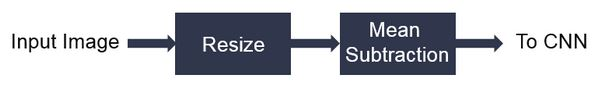
The following code shows the top level wrapper containing the xf::cv::resize() and xf::cv::preProcess() calls.
void pp_pipeline_accel(ap_uint<INPUT_PTR_WIDTH> *img_inp, ap_uint<OUTPUT_PTR_WIDTH> *img_out, int rows_in, int cols_in, int rows_out, int cols_out, float params[3*T_CHANNELS], int th1, int th2)
{
//HLS Interface pragmas
#pragma HLS INTERFACE m_axi     port=img_inp  offset=slave bundle=gmem1
#pragma HLS INTERFACE m_axi     port=img_out  offset=slave bundle=gmem2
#pragma HLS INTERFACE m_axi     port=params  offset=slave bundle=gmem3

#pragma HLS INTERFACE s_axilite port=rows_in     bundle=control
#pragma HLS INTERFACE s_axilite port=cols_in     bundle=control
#pragma HLS INTERFACE s_axilite port=rows_out     bundle=control
#pragma HLS INTERFACE s_axilite port=cols_out     bundle=control
#pragma HLS INTERFACE s_axilite port=th1     bundle=control
#pragma HLS INTERFACE s_axilite port=th2     bundle=control

#pragma HLS INTERFACE s_axilite port=return   bundle=control

xf::cv::Mat<XF_8UC3, HEIGHT, WIDTH, NPC1>   imgInput0(rows_in, cols_in);


xf::cv::Mat<TYPE, NEWHEIGHT, NEWWIDTH, NPC_T> out_mat(rows_out, cols_out);


    hls::stream<ap_uint<256> > resizeStrmout;
    int srcMat_cols_align_npc = ((out_mat.cols + (NPC_T - 1)) >> XF_BITSHIFT(NPC_T)) << XF_BITSHIFT(NPC_T);

    #pragma HLS DATAFLOW

    xf::cv::Array2xfMat<INPUT_PTR_WIDTH,XF_8UC3,HEIGHT, WIDTH, NPC1>  (img_inp, imgInput0);
    xf::cv::resize<INTERPOLATION,TYPE,HEIGHT,WIDTH,NEWHEIGHT,NEWWIDTH,NPC_T,MAXDOWNSCALE> (imgInput0, out_mat);
    xf::cv::accel_utils obj;
    obj.xfMat2hlsStrm<INPUT_PTR_WIDTH, TYPE, NEWHEIGHT, NEWWIDTH, NPC_T, (NEWWIDTH*NEWHEIGHT/8)>(out_mat, resizeStrmout, srcMat_cols_align_npc);
    xf::cv::preProcess <INPUT_PTR_WIDTH, OUTPUT_PTR_WIDTH, T_CHANNELS, CPW, HEIGHT, WIDTH, NPC_TEST, PACK_MODE, X_WIDTH, ALPHA_WIDTH, BETA_WIDTH, GAMMA_WIDTH, OUT_WIDTH, X_IBITS, ALPHA_IBITS, BETA_IBITS, GAMMA_IBITS, OUT_IBITS, SIGNED_IN, OPMODE> (resizeStrmout, img_out, params, rows_out, cols_out, th1, th2);

}
This piepeline is integrated with Deep learning Processign Unit(DPU) as part of Vitis-AI-Library and achieved 11 % speed up compared to software pre-procesing.
- Overall Performance (Images/sec):
- with software pre-processing : 125 images/sec
- with hardware accelerated pre-processing : 140 images/sec
Letterbox
The Letterbox algorithm is used for scaling input image to desired output size while preserving aspect ratio of original image. If required, zeroes are padded for preserving the aspect ratio post resize.
An application of letterbox is in the pre-processing block of machine learning pipelines used in image processing.

The following example demonstrates the Letterbox algorithm.
void letterbox_accel(ap_uint<INPUT_PTR_WIDTH>* img_inp,
                    ap_uint<OUTPUT_PTR_WIDTH>* img_out,
                    int rows_in,
                    int cols_in,
                    int rows_out,
                    int cols_out,
                    int insert_pad_value) {

                    #pragma HLS INTERFACE m_axi     port=img_inp  offset=slave bundle=gmem1
                    #pragma HLS INTERFACE m_axi     port=img_out  offset=slave bundle=gmem2
                    #pragma HLS INTERFACE s_axilite port=rows_in
                    #pragma HLS INTERFACE s_axilite port=cols_in
                    #pragma HLS INTERFACE s_axilite port=rows_out
                    #pragma HLS INTERFACE s_axilite port=cols_out
                    #pragma HLS INTERFACE s_axilite port=insert_pad_value
                    #pragma HLS INTERFACE s_axilite port=return


                    // Compute Resize output image size for Letterbox
                    float scale_height = (float)rows_out/(float)rows_in;
                    float scale_width = (float)cols_out/(float)cols_in;
                    int rows_out_resize, cols_out_resize;
                    if(scale_width<scale_height){
                            cols_out_resize = cols_out;
                            rows_out_resize = (int)((float)(rows_in*cols_out)/(float)cols_in);
                    }
                    else{
                            cols_out_resize = (int)((float)(cols_in*rows_out)/(float)rows_in);
                            rows_out_resize = rows_out;
                    }

                    xf::cv::Mat<TYPE, HEIGHT, WIDTH, NPC_T> imgInput0(rows_in, cols_in);
                    xf::cv::Mat<TYPE, NEWHEIGHT, NEWWIDTH, NPC_T> out_mat_resize(rows_out_resize, cols_out_resize);
                    xf::cv::Mat<TYPE, NEWHEIGHT, NEWWIDTH, NPC_T> out_mat(rows_out, cols_out);

                    #pragma HLS DATAFLOW

                    xf::cv::Array2xfMat<INPUT_PTR_WIDTH,XF_8UC3,HEIGHT, WIDTH, NPC_T>  (img_inp, imgInput0);
                    xf::cv::resize<INTERPOLATION,TYPE,HEIGHT,WIDTH,NEWHEIGHT,NEWWIDTH,NPC_T,MAXDOWNSCALE> (imgInput0, out_mat_resize);
                    xf::cv::insertBorder<TYPE, NEWHEIGHT, NEWWIDTH, NEWHEIGHT, NEWWIDTH, NPC_T>(out_mat_resize, out_mat, insert_pad_value);
                    xf::cv::xfMat2Array<OUTPUT_PTR_WIDTH, TYPE, NEWHEIGHT, NEWWIDTH, NPC_T>(out_mat, img_out);
                    return;
                    }// end kernel
The Letterbox example uses two hardware functions from the Vitis vision library. They are:
- xf::cv::resize
- xf::cv::insertBorder
In the given example, the source image is passed to the xf::cv::resize function. The output of that function is passed to the xf::cv::insertBorder module and the final output image are returned.
Insert Border API Syntax
template <
    int TYPE,
    int SRC_ROWS,
    int SRC_COLS,
    int DST_ROWS,
    int DST_COLS,
    int NPC
    >
void insertBorder (
    xf::cv::Mat <TYPE, SRC_ROWS, SRC_COLS, NPC>& _src,
    xf::cv::Mat <TYPE, DST_ROWS, DST_COLS, NPC>& _dst,
    int insert_pad_val
    )
Parameters:
| TYPE | input and ouput type |
| SRC_ROWS | rows of the input image |
| SRC_COLS | cols of the input image |
| DST_ROWS | rows of the output image |
| DST_COLS | cols of the output image |
| NPC | number of pixels processed per cycle |
| _src | input image |
| _dst | output image |
| insert_pad_val | insert pad value |
Image Sensor Processing pipeline
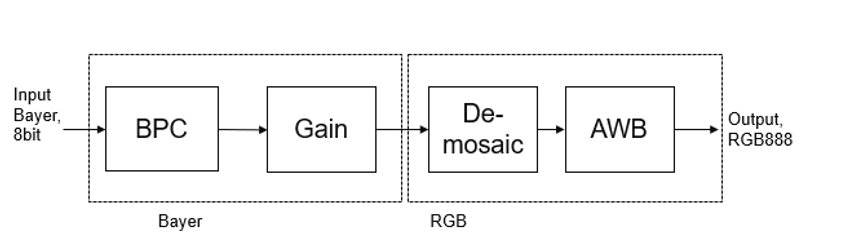
Image Sensor Processing (ISP) is a pipeline of image processing functions processing the raw image from the sensor.
Current ISP includes following 4 blocks:
- BPC (Bad pixel correction) : An image sensor may have a certain number of defective/bad pixels that may be the result of manufacturing faults or variations in pixel voltage levels based on temperature or exposure. Bad pixel correction module removes defective pixels.
- Gain Control : The Gain control module improves the overall brightness of the image.
- Demosaicing : The demosaic module reconstructs RGB pixels from the input Bayer image (RGGB,BGGR,RGBG,GRGB).
- Auto white balance: The AWB module improves color balance of the image by using image statistics.
Current design example demonstrates how to use ISP functions in a pipeline. User can include other modules (like gamma correction, color conversion, resize etc) based on their need.
The following example demonstrates the ISP pipeline.
void ISPPipeline_accel(ap_uint<INPUT_PTR_WIDTH>* img_inp, ap_uint<OUTPUT_PTR_WIDTH>* img_out, int height, int width) {

#pragma HLS INTERFACE m_axi     port=img_inp  offset=slave bundle=gmem1
#pragma HLS INTERFACE m_axi     port=img_out  offset=slave bundle=gmem2
#pragma HLS INTERFACE s_axilite port=height
#pragma HLS INTERFACE s_axilite port=width
#pragma HLS INTERFACE s_axilite port=return
#pragma HLS ARRAY_PARTITION variable=hist0 complete dim=1
#pragma HLS ARRAY_PARTITION variable=hist1 complete dim=1

if (!flag) {
        ISPpipeline(img_inp, img_out, height, width, hist0, hist1);
        flag = 1;
} else {
        ISPpipeline(img_inp, img_out, height, width, hist1, hist0);
        flag = 0;
}
}
void ISPpipeline(ap_uint<INPUT_PTR_WIDTH>* img_inp,
                                 ap_uint<OUTPUT_PTR_WIDTH>* img_out,
                                 int height,
                                 int width,
                                 uint32_t hist0[3][256],
                                 uint32_t hist1[3][256]) {
#pragma HLS INLINE OFF
        xf::cv::Mat<XF_SRC_T, XF_HEIGHT, XF_WIDTH, XF_NPPC> imgInput1(height, width);
        xf::cv::Mat<XF_SRC_T, XF_HEIGHT, XF_WIDTH, XF_NPPC> bpc_out(height, width);
        xf::cv::Mat<XF_SRC_T, XF_HEIGHT, XF_WIDTH, XF_NPPC> gain_out(height, width);
        xf::cv::Mat<XF_DST_T, XF_HEIGHT, XF_WIDTH, XF_NPPC> demosaic_out(height, width);
        xf::cv::Mat<XF_DST_T, XF_HEIGHT, XF_WIDTH, XF_NPPC> impop(height, width);
        xf::cv::Mat<XF_DST_T, XF_HEIGHT, XF_WIDTH, XF_NPPC> _dst(height, width);

#pragma HLS stream variable=bpc_out.data dim=1 depth=2
#pragma HLS stream variable=gain_out.data dim=1 depth=2
#pragma HLS stream variable=demosaic_out.data dim=1 depth=2
#pragma HLS stream variable=imgInput1.data dim=1 depth=2
#pragma HLS stream variable=impop.data dim=1 depth=2
#pragma HLS stream variable=_dst.data dim=1 depth=2

#pragma HLS DATAFLOW


        float inputMin = 0.0f;
        float inputMax = 255.0f;
        float outputMin = 0.0f;
        float outputMax = 255.0f;
        float p = 2.0f;

        xf::cv::Array2xfMat<INPUT_PTR_WIDTH, XF_SRC_T, XF_HEIGHT, XF_WIDTH, XF_NPPC>(img_inp, imgInput1);
        xf::cv::badpixelcorrection<XF_SRC_T, XF_HEIGHT, XF_WIDTH, XF_NPPC, 0, 0>(imgInput1, bpc_out);
        xf::cv::gaincontrol<XF_BAYER_PATTERN, XF_SRC_T, XF_HEIGHT, XF_WIDTH, XF_NPPC>(bpc_out, gain_out);
        xf::cv::demosaicing<XF_BAYER_PATTERN, XF_SRC_T, XF_DST_T, XF_HEIGHT, XF_WIDTH, XF_NPPC, 0>(gain_out, demosaic_out);
        xf::cv::AWBhistogram<XF_DST_T, XF_DST_T, XF_HEIGHT, XF_WIDTH, XF_NPPC, WB_TYPE>(
                demosaic_out, impop, hist0, p, inputMin, inputMax, outputMin, outputMax);
        xf::cv::AWBNormalization<XF_DST_T, XF_DST_T, XF_HEIGHT, XF_WIDTH, XF_NPPC, WB_TYPE>(impop, _dst, hist1, p, inputMin,
                                                                                                                                                                                inputMax, outputMin, outputMax);
        xf::cv::xfMat2Array<OUTPUT_PTR_WIDTH, XF_DST_T, XF_HEIGHT, XF_WIDTH, XF_NPPC>(_dst, img_out);
}