Overview
To facilitate local memory allocation on FPGA devices, the Vitis Vision
library functions are provided in templates with compile-time
parameters. Data is explicitly copied from cv::Mat to xf::cv::Mat
and is stored in physically contiguous memory to achieve the best
possible performance. After processing, the output in xf::cv::Mat is
copied back to cv::Mat to write it into the memory.
xf::cv::Mat Image Container Class
xf::cv::Mat is a template class that serves as a container for storing
image data and its attributes.
Note
The xf::cv::Mat image container class is similar to the cv::Mat class of the OpenCV library.
Class Definition
template <int T, int ROWS, int COLS, int NPC, int XFCVDEPTH = _XFCVDEPTH_DEFAULT>
class Mat {
   public:
        unsigned char allocatedFlag; // flag to mark memory allocation in this class
        int rows, cols, size;        // actual image size

        typedef XF_TNAME(T, NPC) DATATYPE;
        using _DATATTYPE = typename std::conditional<
                (XFCVDEPTH < 0),
                DATATYPE*,                 // Case of Memory Mapped pointer
                typename std::conditional< // Case of Stream
                        (XFCVDEPTH == 0),
                        hls::stream<DATATYPE>,           // Case of default Dtream depth or user can override outside
                        hls::stream<DATATYPE, XFCVDEPTH> // Case of Stream depth specified
                        >::type>::type;
        _DATATTYPE data;

        Mat(); // default constructor
        Mat(Size _sz);
        Mat(int _rows, int _cols);
        Mat(int _size, int _rows, int _cols);
        Mat(int _rows, int _cols, void* _data);
        Mat(const Mat&); // copy constructor

        ~Mat();

        Mat& operator=(const Mat&); // Assignment operator

        template <int D = XFCVDEPTH, typename std::enable_if<(D < 0)>::type* = nullptr>
        void alloc_data() {
#ifndef __SYNTHESIS__
                data = (DATATYPE*)malloc(size * sizeof(DATATYPE));

                if (data == NULL) {
                        fprintf(stderr, "\nFailed to allocate memory\n");
                } else {
                        allocatedFlag = 1;
                }
#endif
        }

        template <int D = XFCVDEPTH, typename std::enable_if<(D >= 0)>::type* = nullptr>
        void alloc_data() {
                // This is a stream
        }

        template <int D = XFCVDEPTH, typename std::enable_if<(D < 0)>::type* = nullptr>
        void free_data() {
                if (data != NULL) {
#ifndef __SYNTHESIS__
                        free(data);
#endif
                }
        }

        template <int D = XFCVDEPTH, typename std::enable_if<(D >= 0)>::type* = nullptr>
        void free_data() {}

        template <int D = XFCVDEPTH, typename std::enable_if<(D < 0)>::type* = nullptr>
        void copyData(const Mat& src) {
                for (int i = 0; i < (rows * ((cols + NPC - 1) >> XF_BITSHIFT(NPC))); ++i) {
                        data[i] = src.data[i];
                }
        }

        template <int D = XFCVDEPTH, typename std::enable_if<(D >= 0)>::type* = nullptr>
        void copyData(const Mat& src) {
                // This is a stream
                assert(0);
        }

        template <int D = XFCVDEPTH, typename std::enable_if<(D < 0)>::type* = nullptr>
        void assignDataPtr(void* _data) {
                data = (DATATYPE*)_data;
        }

        template <int D = XFCVDEPTH, typename std::enable_if<(D >= 0)>::type* = nullptr>
        void assignDataPtr(void* _data) {
                // This is a stream
                assert(0);
        }

        template <int D = XFCVDEPTH, typename std::enable_if<(D < 0)>::type* = nullptr>
        XF_TNAME(T, NPC)
        read(int index) {
                return data[index];
        }

        template <int D = XFCVDEPTH, typename std::enable_if<(D >= 0)>::type* = nullptr>
        XF_TNAME(T, NPC)
        read(int index) {
                return data.read();
        }
        float read_float(int index);

        template <int D = XFCVDEPTH, typename std::enable_if<(D < 0)>::type* = nullptr>
        void write(int index, XF_TNAME(T, NPC) val) {
                data[index] = val;
        }

        template <int D = XFCVDEPTH, typename std::enable_if<(D >= 0)>::type* = nullptr>
        void write(int index, XF_TNAME(T, NPC) val) {
                data.write(val);
        }
        void write_float(int index, float val);

        template <int D = XFCVDEPTH, typename std::enable_if<(D >= 0)>::type* = nullptr>
        void init(int _rows, int _cols, void* _data) {
                init(_rows, _cols);
                copyTo(_data);
        }

        template <int D = XFCVDEPTH, typename std::enable_if<(D < 0)>::type* = nullptr>
        void init(int _rows, int _cols, void* _data) {
                init(_rows, _cols, false);
                assignDataPtr(_data);
        }

        void init(int _rows, int _cols, bool allocate = true);
        void copyTo(void* fromData);
        unsigned char* copyFrom();

        const int type() const;
        const int depth() const;
        const int channels() const;

        template <int DST_T>
        void convertTo(Mat<DST_T, ROWS, COLS, NPC, XFCVDEPTH>& dst, int otype, double alpha = 1, double beta = 0);
};
Parameter Descriptions
The following table lists the xf::cv::Mat class parameters and their
descriptions:
| Parameter | Description |
|---|---|
| rows | The number of rows in the image or height of the image. |
| cols | The number of columns in the image or width of the image. |
| size | The number of words stored in the data member. The
value is calculated using
rows*cols/(number of pixels packed per word). |
| allocatedFlag | Flag for memory allocation status |
| *data | class parameters and the pointer to the words that store the pixels of the image. |
The following table lists the member functions and their descriptions:
| Member Functions | Description |
|---|---|
| Mat() | This default constructor initializes the Mat object sizes, using the template parameters ROWS and COLS. |
| Mat(int _rows, int _cols) | This constructor initializes the Mat object using arguments _rows and _cols. |
| Mat(const xf::cv::Mat &_src) | This constructor helps clone a Mat object to another. New memory will be allocated for the newly created constructor. |
| Mat(int _rows, int _cols, void *_data) | This constructor initializes the Mat object using arguments _rows, _cols, and _data. The *data member of the Mat object points to the memory allocated for _data argument, when this constructor is used. No new memory is allocated for the *data member. |
| convertTo(Mat <DST_T,ROWS, COLS, NPC> &dst, int otype, double alpha=1, double beta=0) | Refer to xf::cv::convertTo |
| copyTo(* fromData) | Copies the data from Data pointer into physically contiguous memory allocated inside the constructor. |
| copyFrom() | Returns the pointer to the first location of the *data member. |
| read(int index) | Readout a value from a given location and return it as a packed (for multi-pixel/clock) value. |
| read_float(in t index) | Readout a value from a given location and return it as a float value |
| write(int index, XF_TNAME(T,NP C) val) | Writes a packed (for multi-pixel/clock) value into the given location. |
| write_float(i nt index, float val) | Writes a float value into the given location. |
| type() | Returns the type of the image. |
| depth() | Returns the depth of the image |
| channels() | Returns number of channels of the image |
| ~Mat() | This is a default destructor of the Mat object. |
Template parameters of the xf::cv::Mat class are used to set the depth
of the pixel, number of channels in the image, number of pixels packed
per word, maximum number of rows and columns of the image. The following
table lists the template parameters and their descriptions:
| Parameters | Description |
|---|---|
| TYPE | Type of the pixel data. For example, XF_8UC1 stands for 8-bit unsigned and one channel pixel. More types can be found in include/common/xf_params.h. |
| HEIGHT | Maximum height of an image. |
| WIDTH | Maximum width of an image. |
| NPC | The number of pixels to be packed per word. For instance, XF_NPPC1 for 1 pixel per word; and XF_NPPC8 for 8 pixels per word. |
Pixel-Level Parallelism
The amount of parallelism to be implemented in a function from Vitis Vision is kept as a configurable parameter. In most functions, there are two options for processing data.
- Single-pixel processing
- Processing eight pixels in parallel
The following table describes the options available for specifying the level of parallelism required in a particular function:
| Option | Description |
|---|---|
| XF_NPPC1 | Process 1 pixel per clock cycle |
| XF_NPPC2 | Process 2 pixels per clock cycle |
| XF_NPPC4 | Process 4 pixels per clock cycle |
| XF_NPPC8 | Process 8 pixels per clock cycle |
Macros to Work With Parallelism
There are two macros that are defined to work with parallelism.
- The
XF_NPIXPERCYCLE(flags)macro resolves to the number of pixels processed per cycle.XF_NPIXPERCYCLE(XF_NPPC1)resolves to 1XF_NPIXPERCYCLE(XF_NPPC2)resolves to 2XF_NPIXPERCYCLE(XF_NPPC4)resolves to 4XF_NPIXPERCYCLE(XF_NPPC8)resolves to 8
- The
XF_BITSHIFT(flags)macro resolves to the number of times to shift the image size to right to arrive at the final data transfer size for parallel processing.XF_BITSHIFT(XF_NPPC1)resolves to 0XF_BITSHIFT(XF_NPPC2)resolves to 1XF_BITSHIFT(XF_NPPC4)resolves to 2XF_BITSHIFT(XF_NPPC8)resolves to 3
Data Types
Data types will differ, depending on the combination of the depth of pixels and the number of channels in the image. The generic nomenclature of the parameter is listed below.
XF_<Number of bits per pixel><signed (S) or unsigned (U) or float (F)>C<number of channels>
For example, for an 8-bit pixel - unsigned - 1 channel the data type is
XF_8UC1.
The following table lists the available data types for the xf::cv::Mat
class:
| Option | Number of bits per Pixel | Unsigned/ Signed/ Float Type | Number of Channels |
|---|---|---|---|
| XF_2UC1 | 2 | Unsigned | 1 |
| XF_8UC1 | 8 | Unsigned | 1 |
| XF_8UC2 | 8 | Unsigned | 2 |
| XF_8UC3 | 8 | Unsigned | 3 |
| XF_8UC4 | 8 | Unsigned | 4 |
| XF_10UC1 | 10 | Unsigned | 1 |
| XF_10UC2 | 10 | Unsigned | 2 |
| XF_10UC3 | 10 | Unsigned | 3 |
| XF_10UC4 | 10 | Unsigned | 4 |
| XF_12UC1 | 12 | Unsigned | 1 |
| XF_12UC2 | 12 | Unsigned | 2 |
| XF_12UC3 | 12 | Unsigned | 3 |
| XF_12UC4 | 12 | Unsigned | 4 |
| XF_16UC1 | 16 | Unsigned | 1 |
| XF_16SC1 | 16 | Signed | 1 |
| XF_32UC1 | 32 | Unsigned | 1 |
| XF_32FC1 | 32 | Float | 1 |
| XF_32FC3 | 32 | Float | 3 |
| XF_32SC1 | 32 | Signed | 1 |
Manipulating Data Type
Based on the number of pixels to process per clock cycle and the type
parameter, there are different possible data types. The Vitis Vision library
uses these datatypes for internal processing and inside the xf::cv::Mat
class. The following are a few supported types:
XF_TNAME(TYPE,NPPC)resolves to the data type of the data member of thexf::cv::Matobject. For instance,XF_TNAME(XF_8UC1,XF_NPPC8)resolves toap_uint<64>.Word width = pixel depth * number of channels * number of pixels to process per cycle (NPPC).XF_DTUNAME(TYPE,NPPC)resolves to the data type of the pixel. For instance,XF_DTUNAME(XF_32FC1,XF_NPPC1)resolves tofloat.XF_PTSNAME(TYPE,NPPC)resolves to the ‘C’ data type of the pixel. For instance,XF_PTSNAME (XF_16UC1,XF_NPPC2)resolves tounsigned short.
Note
ap_uint<>, ap_int<>, ap_fixed<>, and ap_ufixed<> types belong to the high-level synthesis (HLS) library. For more information, see the Vivado Design Suite User Guide: High-Level Synthesis (UG902).
xf::cv::imread
The function xf::cv::imread loads an image from the specified file path, copies into xf::cv::Mat and returns it. If the image cannot be read (because of missing file, improper permissions, unsupported or invalid format), the function exits with a non-zero return code and an error statement.
Note
In an HLS standalone mode like Cosim, use cv::imread followed by copyTo function, instead of xf::cv::imread.
API Syntax
template<int PTYPE, int ROWS, int COLS, int NPC>
xf::cv::Mat<PTYPE, ROWS, COLS, NPC> imread (char *filename, int type)
Parameter Descriptions
The table below describes the template and the function parameters.
| Parameter | Description |
|---|---|
| PTYPE | Input pixel type. Value should be in accordance with the ‘type’ argument’s value. |
| ROWS | Maximum height of the image to be read |
| COLS | Maximum width of the image to be read |
| NPC | Number of pixels to be processed per cycle; possible options are XF_NPPC1 and XF_NPPC8 for 1 pixel and 8 pixel operations respectively. |
| filename | Name of the file to be loaded |
| type | Flag that depicts the type of image. The values are:
|
xf::cv::imwrite
The function xf::cv::imwrite saves the image to the specified file from the given xf::cv::Mat. The image format is chosen based on the file name extension. This function internally uses cv::imwrite for the processing. Therefore, all the limitations of cv::imwrite are also applicable to xf::cv::imwrite.
API Syntax
template <int PTYPE, int ROWS, int COLS, int NPC>
void imwrite(const char *img_name, xf::cv::Mat<PTYPE, ROWS, COLS, NPC> &img)
Parameter Descriptions
The table below describes the template and the function parameters.
| Parameter | Description |
|---|---|
| PTYPE | Input pixel type. Supported types are: XF_8UC1, XF_16UC1, XF_8UC4, and XF_16UC4 |
| ROWS | Maximum height of the image to be read |
| COLS | Maximum width of the image to be read |
| NPC | Number of pixels to be processed per cycle; possible options are XF_NPPC1 and XF_NPPC8 for 1 pixel and 8 pixel operations respectively. |
| img_name | Name of the file with the extension |
| img | xf::cv::Mat array to be saved |
xf::cv::absDiff
The function xf::cv::absDiff computes the absolute difference between each individual pixels of an xf::cv::Mat and a cv::Mat, and returns the difference values in a cv::Mat.
API Syntax
template <int PTYPE, int ROWS, int COLS, int NPC>
void absDiff(cv::Mat &cv_img, xf::cv::Mat<PTYPE, ROWS, COLS, NPC>& xf_img, cv::Mat &diff_img )
Parameter Descriptions
The table below describes the template and the function parameters.
| Parameter | Description |
|---|---|
| PTYPE | Input pixel type |
| ROWS | Maximum height of the image to be read |
| COLS | Maximum width of the image to be read |
| NPC | Number of pixels to be processed per cycle; possible options are XF_NPPC1, XF_NPPC4, and XF_NPPC8 for 1-pixel, 4-pixel, and 8-pixel parallel operations respectively. |
| cv_img | cv::Mat array to be compared |
| xf_img | xf::cv::Mat array to be compared |
| diff_img | Output difference image(cv::Mat) |
xf::cv::convertTo
The xf::cv::convertTo function performs bit depth conversion on each individual pixel of the given input image. This method converts the source pixel values to the target data type with appropriate casting.
dst(x,y)= cast<target-data-type>(α(src(x,y)+β))
Note: The output and input Mat cannot be the same. That is, the converted image cannot be stored in the Mat of the input image.
API Syntax
template<int DST_T> void convertTo(xf::cv::Mat<DST_T,ROWS, COLS, NPC> &dst, int ctype, double alpha=1, double beta=0)
Parameter Descriptions
The table below describes the template and function parameters.
| Parameter | Description |
|---|---|
| DST_T | Output pixel type. Possible values are XF_8UC1, XF_16UC1, XF_16SC1, and XF_32SC1. |
| ROWS | Maximum height of image to be read |
| COLS | Maximum width of image to be read |
| NPC | Number of pixels to be processed per cycle; possible options are XF_NPPC1, XF_NPPC4, and XF_NPPC8 for 1-pixel, 4-pixel, and 8-pixel parallel operations respectively. XF_32SC1 and XF_NPPC8 combination is not supported. |
| dst | Converted xf Mat |
| ctype | Conversion type : Possible values are listed here.
//Up-convert:
|
| alpha | Optional scale factor |
| beta | Optional delta added to the scaled values |
Vitis Vision Library Functions
The Vitis Vision library is a set of select OpenCV functions optimized for Zynq-7000, Zynq UltraScale+ MPSoC, Alveo U200 and U50 devices. The maximum resolution supported for all the functions is 4K, except Houghlines and HOG (RB mode).
Note
Resolution Conversion (Resize) in 8 pixel per cycle mode, Dense Pyramidal LK Optical Flow, and Dense Non-Pyramidal LK Optical Flow functions are not supported on the Zynq-7000 SoC ZC702 devices, due to the higher resource utilization.
Note
Number of pixel per clock depends on the maximum bus width a device can support. For example: Zynq-7000 SoC has 64-bit interface and so for a pixel type 16UC1, maximum of four pixel per clock (XF_NPPC4) is possible.
Absolute Difference
API Syntax
The absdiff function finds the pixel wise absolute difference
between two input images and returns an output image. The input and the
output images must be the XF_8UC1 type.
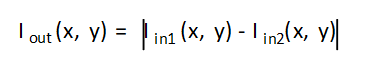
Where,
- Iout(x, y) is the intensity of output image at (x,y) position.
- Iin1(x, y) is the intensity of first input image at (x,y) position.
- Iin2(x, y) is the intensity of second input image at (x,y) position.
template<int SRC_T, int ROWS, int COLS, int NPC=1>
void absdiff(
xf::cv::Mat<int SRC_T, int ROWS, int COLS, int NPC> src1,
xf::cv::Mat<int SRC_T, int ROWS, int COLS, int NPC> src2,
xf::cv::Mat<int SRC_T, int ROWS, int COLS, int NPC> dst )
Parameter Descriptions
The following table describes the template and the function parameters.
| Parameter | Description |
|---|---|
| SRC_T | Input and Output pixel type. Only 8-bit, unsigned, 1 and 3 channels are supported (XF_8UC1 and XF_8UC3) |
| ROWS | Maximum height of input and output image. |
| COLS | Maximum width of input and output image. Must be multiple of 8, for 8-pixel operation. |
| NPC | Number of pixels to be processed per cycle; possible options are XF_NPPC1 and XF_NPPC8 for 1 pixel and 8 pixel operations respectively. |
| src1 | Input image |
| src2 | Input image |
| dst | Output image |
Resource Utilization
The following table summarizes the resource utilization in different configurations, generated using Vivado HLS 2019.1 tool for the Xczu9eg-ffvb1156-1-i-es1 FPGA, to process a grayscale HD (1080x1920) image.
| Operating Mode | Operating Frequency (MHz) | Utilization Estimate | ||||
|---|---|---|---|---|---|---|
| BRAM_18K | DSP_48Es | FF | LUT | CLB | ||
| 1 Pixel | 300 | 0 | 0 | 62 | 67 | 17 |
| 8 Pixel | 150 | 0 | 0 | 67 | 234 | 39 |
Performance Estimate
The following table summarizes the performance in different configurations, as generated using Vivado HLS 2019.1 tool for the Xczu9eg-ffvb1156-1-i-es1, to process a grayscale HD (1080x1920) image.
| Operating Mode | Latency Estimate |
|---|---|
| Max Latency (ms) | |
| 1 pixel operation (300 MHz) | 6.9 |
| 8 pixel operation (150 MHz) | 1.69 |
Deviation from OpenCV
There is no deviation from OpenCV, except that the absdiff function
supports 8-bit pixels.
Accumulate
The accumulate function adds an image (src1) to the accumulator
image (src2), and generates the accumulated result image (dst).

API Syntax
template<int SRC_T, int DST_T, int ROWS, int COLS, int NPC=1>
void accumulate (
xf::cv::Mat<int SRC_T, int ROWS, int COLS, int NPC> src1,
xf::cv::Mat<int SRC_T, int ROWS, int COLS, int NPC> src2,
xf::cv::Mat<int DST_T, int ROWS, int COLS, int NPC> dst )
Parameter Descriptions
The following table describes the template and the function parameters.
| Parameter | Description |
|---|---|
| SRC_T | Input pixel type. Only 8-bit, unsigned, 1 and 3 channels are supported (XF_8UC1 and XF_8UC3) |
| DST_T | Output pixel type. Only 16-bit, unsigned, 1 and 3 channels are supported (XF_16UC1 and XF_16UC3) |
| ROWS | Maximum height of input and output image. |
| COLS | Maximum width of input and output image. Recommend using a multiple of 8, for an 8-pixel operation. |
| NPC | Number of pixels to be processed per cycle; possible options are XF_NPPC1 and XF_NPPC8 for 1 pixel and 8 pixel operations respectively. |
| src1 | Input image |
| src2 | Input image |
| dst | Output image |
Resource Utilization
The following table summarizes the resource utilization in different configurations, generated using Vivado HLS 2019.1 tool for the Xczu9eg-ffvb1156-1-i-es1, to process a grayscale HD (1080x1920) image.
| Operating Mode | Operating Frequency (MHz) | Utilization Estimate | ||||
|---|---|---|---|---|---|---|
| BRAM_18K | DSP_48Es | FF | LUT | CLB | ||
| 1 Pixel | 300 | 0 | 0 | 62 | 55 | 12 |
| 8 Pixel | 150 | 0 | 0 | 389 | 285 | 61 |
The following table summarizes the resource utilization in different configurations, generated using Vivado HLS 2019.1 tool for the Xczu9eg-ffvb1156-1-i-es1, to process 4K 3 Channel image.
| Operating Mode | Operating Frequency (MHz) | Utilization Estimate | ||||
|---|---|---|---|---|---|---|
| BRAM_18K | DSP_48Es | FF | LUT | CLB | ||
| 1 Pixel | 300 | 0 | 1 | 207 | 72 | 32 |
Performance Estimate
The following table summarizes the performance in different configurations, as generated using Vivado HLS 2019.1 tool for the Xczu9eg-ffvb1156-1-i-es1, to process a grayscale HD (1080x1920) image.
| Operating Mode | Latency Estimate |
|---|---|
| Max Latency (ms) | |
| 1 pixel operation (300 MHz) | 6.9 |
| 8 pixel operation (150 MHz) | 1.7 |
Deviation from OpenCV

Whereas, in the Vitis Vision implementation, the accumulated image is stored separately, as shown below:

Accumulate Squared
The accumulateSquare function adds the square of an image (src1) to
the accumulator image (src2) and generates the accumulated result (dst).

The accumulated result is a separate argument in the function, instead of having src2 as the accumulated result. In this implementation, having a bi-directional accumulator is not possible as the function makes use of streams.
API Syntax
template<int SRC_T, int DST_T, int ROWS, int COLS, int NPC=1>
void accumulateSquare (
xf::cv::Mat<int SRC_T, int ROWS, int COLS, int NPC> src1,
xf::cv::Mat<int SRC_T, int ROWS, int COLS, int NPC> src2,
xf::cv::Mat<int DST_T, int ROWS, int COLS, int NPC> dst)
Parameter Descriptions
The following table describes the template and the function parameters.
| Parameter | Description |
|---|---|
| SRC_T | Input pixel type. Only 8-bit, unsigned, 1 and 3 channels are supported (XF_8UC1 and XF_8UC3) |
| DST_T | Output pixel type. Only 16-bit, unsigned, 1 and 3 channels are supported (XF_16UC1 and XF_16UC3) |
| ROWS | Maximum height of input and output image. |
| COLS | Maximum width of input and output image (must be multiple of 8, for 8-pixel operation) |
| NPC | Number of pixels to be processed per cycle; possible options are XF_NPPC1 and XF_NPPC8 for 1 pixel and 8 pixel operations respectively. |
| src1 | Input image |
| src2 | Input image |
| dst | Output image |
Resource Utilization
The following table summarizes the resource utilization in different configurations, generated using Vivado HLS 2019.1 tool for the Xczu9eg-ffvb1156-1-i-es1 FPGA, to process a grayscale HD (1080x1920) image.
| Operating Mode | Operating Frequency (MHz) | Utilization Estimate | ||||
|---|---|---|---|---|---|---|
| BRAM_18K | DSP_48Es | FF | LUT | CLB | ||
| 1 Pixel | 300 | 0 | 1 | 71 | 52 | 14 |
| 8 Pixel | 150 | 0 | 8 | 401 | 247 | 48 |
The following table summarizes the resource utilization in different configurations, generated using Vivado HLS 2019.1 tool for the Xczu9eg-ffvb1156-1-i-es1 FPGA, to process 4K 3 Channel image.
| Operating Mode | Operating Frequency (MHz) | Utilization Estimate | ||||
|---|---|---|---|---|---|---|
| BRAM_18K | DSP_48Es | FF | LUT | CLB | ||
| 1 Pixel | 300 | 0 | 3 | 227 | 86 | 37 |
Performance Estimate
The following table summarizes the performance in different configurations, as generated using Vivado HLS 2019.1 tool for the Xczu9eg-ffvb1156-1-i-es1, to process a grayscale HD (1080x1920) image.
| Operating Mode | Latency Estimate |
|---|---|
| Max Latency (ms) | |
| 1 pixel operation (300 MHz) | 6.9 |
| 8 pixel operation (150 MHz) | 1.6 |
Deviation from OpenCV
In OpenCV the accumulated squared image is stored in the second input image. The src2 image acts as input as well as output.


Accumulate Weighted
The accumulateWeighted function computes the weighted sum of the
input image (src1) and the accumulator image (src2) and generates the
result in dst.

The accumulated result is a separate argument in the function, instead of having src2 as the accumulated result. In this implementation, having a bi-directional accumulator is not possible, as the function uses streams.
API Syntax
template<int SRC_T, int DST_T, int ROWS, int COLS, int NPC=1>
void accumulateWeighted (
xf::cv::Mat<int SRC_T, int ROWS, int COLS, int NPC> src1,
xf::cv::Mat<int SRC_T, int ROWS, int COLS, int NPC> src2,
xf::cv::Mat<int DST_T, int ROWS, int COLS, int NPC> dst,
float alpha )
Parameter Descriptions
The following table describes the template and the function parameters.
| Parameter | Description |
|---|---|
| SRC_T | Input pixel type. Only 8-bit, unsigned, 1 and 3 channels are supported (XF_8UC1 and XF_8UC3) |
| DST_T | Output pixel type. Only 16-bit, unsigned, 1 and 3 channels are supported (XF_16UC1 and XF_16UC3) |
| ROWS | Maximum height of input and output image. |
| COLS | Maximum width of input and output image. Recommend multiples of 8, for an 8-pixel operation. |
| NPC | Number of pixels to be processed per cycle; possible options are XF_NPPC1 and XF_NPPC8 for 1 pixel and 8 pixel operations respectively. |
| src1 | Input image |
| src2 | Input image |
| dst | Output image |
| alpha | Weight applied to input image |
Resource Utilization
The following table summarizes the resource utilization in different configurations, generated using Vivado HLS 2019.1 tool for the Xczu9eg-ffvb1156-1-i-es1 FPGA, to process a grayscale HD (1080x1920) image.
| Operating Mode | Operating Frequency (MHz) | Utilization Estimate | ||||
|---|---|---|---|---|---|---|
| BRAM_18K | DSP_48Es | FF | LUT | CLB | ||
| 1 Pixel | 300 | 0 | 5 | 295 | 255 | 52 |
| 8 Pixel | 150 | 0 | 19 | 556 | 476 | 88 |
The following table summarizes the resource utilization in different configurations, generated using Vivado HLS 2019.1 tool for the Xczu9eg-ffvb1156-1-i-es1 FPGA, to process a 4K 3 Channel image.
| Operating Mode | Operating Frequency (MHz) | Utilization Estimate | ||||
|---|---|---|---|---|---|---|
| BRAM_18K | DSP_48Es | FF | LUT | CLB | ||
| 1 Pixel | 300 | 0 | 9 | 457 | 387 | 95 |
Performance Estimate
The following table summarizes the performance in different configurations, as generated using Vivado HLS 2019.1 tool for the Xczu9eg-ffvb1156-1-i-es1, to process a grayscale HD (1080x1920) image.
| Operating Mode | Latency Estimate |
|---|---|
| Max Latency (ms) | |
| 1 pixel operation (300 MHz) | 6.9 |
| 8 pixel operation (150 MHz) | 1.7 |
Deviation from OpenCV
The resultant image in OpenCV is stored in the second input image. The src2 image acts as input as well as output, as shown below:

Whereas, in Vitis Vision implementation, the accumulated weighted image is stored separately.

AddS
The AddS function performs the addition operation between pixels of input image src and given scalar value scl and stores the result in dst.
dst(x,y)= src(x,y) + scl
Where (x,y) is the spatial coordinate of the pixel.
API Syntax
template<int POLICY_TYPE, int SRC_T, int ROWS, int COLS, int NPC =1>
void addS(xf::cv::Mat<SRC_T, ROWS, COLS, NPC> & _src1, unsigned char _scl[XF_CHANNELS(SRC_T,NPC)],xf::cv::Mat<SRC_T, ROWS, COLS, NPC> & _dst)
Parameter Descriptions
The following table describes the template and the function parameters.
| Parameter | Description |
|---|---|
| SRC_T | Input pixel type. 8-bit, unsigned, 1 channel is supported (XF_8UC1). |
| ROWS | Maximum height of input and output image. |
| COLS | Maximum width of input and output image. In case of N-pixel parallelism, width should be multiple of N. |
| NPC | Number of pixels to be processed per cycle; possible options are XF_NPPC1 and XF_NPPC8 for 1 pixel and 8 pixel operations respectively. |
| _src1 | First input image |
| _scl | Input scalar value, the size should be number of channels. |
| _dst | Output image |
Resource Utilization
The following table summarizes the resource utilization of the AddS function in both the resource optimized (8 pixel) mode and normal mode, as generated using Vivado HLS 2019.1 version tool for the Xczu9eg-ffvb1156-1-i-es1 FPGA.
| Name | Resource Utilization | |
|---|---|---|
| 1 pixel per clock operation | 8 pixel per clock operation | |
| 300 MHz | 150 MHz | |
| BRAM_18K | 0 | 0 |
| DSP48E | 0 | 0 |
| FF | 100 | 101 |
| LUT | 52 | 185 |
| CLB | 20 | 45 |
Performance Estimate
The following table summarizes a performance estimate of the kernel in different configurations, generated using Vivado HLS 2019.1 tool for Xczu9eg-ffvb1156-1-i-es1 FPGA to process a grayscale HD (1080x1920) image.
| Operating Mode | Latency Estimate |
|---|---|
| Max Latency (ms) | |
| 1 pixel operation (300 MHz) | 6.9 |
| 8 pixel operation (150 MHz) | 1.7 |
Add Weighted
The addweighted function calculates a weighted sum of two input images src1, src2 and generates the result in dst.
dst(x,y)= src1(x,y)*alpha+src2(x,y)*beta+ gamma
API Syntax
template< int SRC_T , int DST_T,   int ROWS, int COLS, int NPC=1>
void addWeighted(xf::cv::Mat<SRC_T, ROWS, COLS, NPC> & _src1, float alpha, xf::cv::Mat<SRC_T, ROWS, COLS, NPC> & _src2, float beta, float gamma, xf::cv::Mat<SRC_T, ROWS, COLS, NPC> & _dst)
Parameter Descriptions
The following table describes the template and the function parameters.
| Parameter | Description |
|---|---|
| SRC_T | Input Pixel Type. 8-bit, unsigned,1 channel is supported (XF_8UC1) |
| DST_T | Output Pixel Type. 8-bit, unsigned,1 channel is supported (XF_8UC1) |
| ROWS | Maximum height of input and output image |
| COLS | Maximum width of input and output image. In case of N-pixel parallelism, width should be multiple of N |
| NPC | Number of pixels to be processed per cycle; possible options are XF_NPPC1 and XF_NPPC8 for 1 pixel and 8 pixel operations respectively. |
| _src1 | First Input image |
| Alpha | Weight applied on first image |
| _src2 | Second Input image |
| Beta | Weight applied on second image |
| gamma | Scalar added to each sum |
| _dst | Output image |
Resource Utilization
The following table summarizes the resource utilization of the Addweighted function in Resource optimized (8 pixel) mode and normal mode, as generated in Vivado HLS 2019.1 version tool for the Xczu9eg-ffvb1156-1-i-es1 FPGA.
| Name | Resource Utilization | |
|---|---|---|
| 1 pixel per clock operation | 8 pixel per clock operation | |
| 300 MHz | 150 MHz | |
| BRAM_18K | 0 | 0 |
| DSP48E | 11 | 25 |
| FF | 903 | 680 |
| LUT | 851 | 1077 |
| CLB | 187 | 229 |
Performance Estimate
The following table summarizes a performance estimate of the kernel in different configurations, generated using Vivado HLS 2019.1 tool for Xczu9eg-ffvb1156-1-i-es1 FPGA to process a grayscale HD (1080x1920) image.
| Operating Mode | Latency Estimate |
|---|---|
| Max Latency (ms) | |
| 1 pixel operation (300 MHz) | 6.9 |
| 8 pixel operation (150 MHz) | 1.7 |
Auto Exposure Correction
Auto exposure correction improves contrast and brightness of the image and also corrects the exposure of the input frame. The algorithm uses luminence histogram equalization to improve overall exposure and contrast of the image. Luminence (V) is extracted after converting input image to HSV color space. Once the algorthm is applied the image is converted back to RGB color space.
API Syntax
template <int SRC_T, int DST_T, int SIN_CHANNEL_TYPE, int ROWS, int COLS, int NPC = 1>
void autoexposurecorrection(xf::cv::Mat<SRC_T, ROWS, COLS, NPC>& src,
                            xf::cv::Mat<DST_T, ROWS, COLS, NPC>& dst,
                            unsigned int hist_array1[1][256],
                            unsigned int hist_array2[1][256])
Parameter Descriptions
The following table describes template parameters and arguments of the function.
| Parameter | Description |
|---|---|
| SRC_T | Input pixel type. 8-bit unsigned 3 channel is supported (XF_8UC3). |
| DST_T | Output pixel type. 8-bit unsigned 3 channel is supported (XF_8UC3). |
| ROWS | Maximum height of input and output image |
| COLS | Maximum width of input and output image. In case of N-pixel parallelism, width should be multiple of N. |
| SIN_CHANNEL_TYPE | Single channel type. should be XF_8UC1 |
| NPC | Number of pixels to be processed per cycle; possible options is XF_NPPC1, XF_NPPC2 AND so on |
| src | Input image |
| dst | Output image |
| hist_array1 | Histogram array |
| hist_array2 | Histogram array |
Resource Utilization
The following table summarizes the resource utilization of kernel in different configurations, generated using Vitis HLS 2020.2 tool, to process a FULL HD image.
| Operating Mode | Operating Frequency (MHz) | Utilization Estimate | ||||
|---|---|---|---|---|---|---|
| BRAM_18K | DSP_48Es | FF | LUT | CLB | ||
| 1 pixel | 300 | 4 | 18 | 6713 | 2996 | 1103 |
| 2 pixel | 300 | 4 | 27 | 7618 | 3705 | 1257 |
Performance Estimate
The following table summarizes a performance estimate of the kernel in different configurations, as generated using Vitis HLS 2020.2 tool, to process a FULL HD image.
| Operating Mode | Operating Frequency (MHz) | Latency Estimate Max (ms) |
|---|---|---|
| 1 pixel | 300 | 7 |
| 2 pixel | 300 | 3.7 |
Auto White Balance
Grayworld whitebalancing algorithm:
This algorithm scales the values of pixels based on a gray-world assumption which states that the average of all channels should result in a gray image. It adds a modification which thresholds pixels based on their saturation value and only uses pixels below the provided threshold in finding average pixel values. Saturation is calculated using the following for a 3-channel RGB image per pixel I and is in the range [0, 1]:
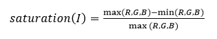
A threshold of 1 means that all pixels are used to white-balance, while a threshold of 0 means no pixels are used. Lower thresholds are useful in white-balancing saturated images.
Simple whitebalancing algorithm:
A simple white balance algorithm that works by independently stretching each of the input image channels to the specified range(maximum and minimum). Computes channel wise intensity histogram and ignores p% maximum and minimum values and finally normalize each channel with min and max. For increased robustness it ignores the top and bottom \(p\%\ \ (4\%\ is\ fixed)\) of pixel values.
API Syntax for Simple white balance
template <int SRC_T, int DST_T, int ROWS, int COLS, int NPC = 1, int WB_TYPE, int HIST_SIZE>
void AWBhistogram(xf::cv::Mat<SRC_T, ROWS, COLS, NPC>& src1,
              xf::cv::Mat<SRC_T, ROWS, COLS, NPC>& src2,
              uint32_t histogram[3][HIST_SIZE],
              float thresh,
              float inputMin,
              float inputMax,
              float outputMin,
              float outputMax)

template <int SRC_T, int DST_T, int ROWS, int COLS, int NPC = 1, int WB_TYPE, int HIST_SIZE, int S_DEPTH = 2>
void AWBNormalization(xf::cv::Mat<SRC_T, ROWS, COLS, NPC>& src,
                  xf::cv::Mat<DST_T, ROWS, COLS, NPC, S_DEPTH>& dst,
                  uint32_t histogram[3][HIST_SIZE],
                  float thresh,
                  float inputMin,
                  float inputMax,
                  float outputMin,
                  float outputMax)
API Syntax for Grayworld white balance
template <int SRC_T, int DST_T, int ROWS, int COLS, int NPC = 1, int WB_TYPE>
void AWBChannelGain(xf::cv::Mat<SRC_T, ROWS, COLS, NPC>& src,
                xf::cv::Mat<DST_T, ROWS, COLS, NPC>& dst,
                float thresh,
                int i_gain[3])

template <int SRC_T, int DST_T, int ROWS, int COLS, int NPC = 1, int WB_TYPE, int S_DEPTH = 2>
void AWBGainUpdate(xf::cv::Mat<SRC_T, ROWS, COLS, NPC>& src1,
               xf::cv::Mat<DST_T, ROWS, COLS, NPC, S_DEPTH>& src2,
               float thresh,
               int i_gain[3])
Parameter Descriptions
The following table describes the template and the function parameters.
| Parameter | Description |
|---|---|
| SRC_T | Input Pixel Type. |
| DST_T | Output Pixel Type. |
| ROWS | Maximum height of input and output image (Must be multiple of NPC) |
| COLS | Maximum width of input and output image (Must be multiple of NPC) |
| NPC | Number of Pixels to be processed per cycle. |
| WB_TYPE | White balance type. Supported types are Gray world and simple. |
| HIST_SIZE | Histogram size. |
| Src1 | Input image. |
| Src2 | Input image. |
| histogram | Histogram array for the Simple AWB. |
| i_gain | Gain values for gray-world AWB. |
| dst | Output image. |
| thresh | Threshold value, which is used in gray world white balance method to compute average pixel values below the threshold value. |
| inputMin | Input image range minimum value. |
| inputMax | Input image range maximum value. |
| outputMin | Output image range minimum value. |
| outputMax | Output image range maximum value. |
Resource Utilization
The following table summarizes the resource utilization of the kernel in different configurations, generated using Vitis HLS 2020.1 tool for the Xilinx xc7vx485t-ffg1157-1 FPGA, to process a 4K image.
| Operating Mode | Operating Frequency (MHz) |
Utilization Estimate | ||||
|---|---|---|---|---|---|---|
| BRAM_18K | DSP_48Es | FF | LUT | CLB | ||
| 1 pixel | 300 | 14 | 10 | 4798 | 4953 | 1757 |
| 2 pixel | 300 | 14 | 10 | 8335 | 8535 | 2901 |
Performance Estimate
The following table summarizes a performance estimate of the kernel in different configurations, as generated using Vitis HLS 2020.1 tool for the Xilinx xc7vx485t-ffg1157-1 FPGA, to process a 4K image.
| Operating Mode | Operating Frequency (MHz) |
Latency Estimate |
|---|---|---|
| Max (ms) | ||
| 1 pixel | 300 | 55.2 for still image(27.9 for video stream) |
| 2 pixel | 300 | 28 for still image(14.2 for video stream) |
Bad Pixel Correction
An image sensor may have a certain number of defective/bad pixels that may be the result of manufacturing faults or variations in pixel voltage levels based on temperature or exposure. The Badpixelcorrection module removes the defective pixels in the image using below operation.
If the middle pixel value is lesser than minimum neighborhood value, will consider minimum neighborhood value as mid pixel, otherwise mid pixel value is greater than maximum neighborhood value, will consider maximum neighborhood as mid pixel.
API Syntax
template<int TYPE, int ROWS, int COLS, int NPPC=1, int BORDER_T=XF_BORDER_CONSTANT, int USE_URAM=0>void badpixelcorrection(xf::cv::Mat<TYPE, ROWS, COLS, NPPC> &_src,xf::cv::Mat<TYPE, ROWS, COLS, NPPC> &_dst)
The following table describes the template and the function parameters.
| Parameter | Description |
|---|---|
| TYPE | Input and Output Pixel Type. |
| ROWS | Maximum height of input and output image (Must be multiple of NPPC) |
| COLS | Maximum width of input and output image (Must be multiple of NPPC) |
| NPPC | Number of Pixels to be processed per cycle. |
| BORDER_T | Border Type supported is XF_BORDER_CONSTANT |
| USE_URAM | Enable to map storage structures to UltraRAM. |
| _src | Input Bayer image |
| _dst | Output Bayer image |
Resource Utilization
The following table summarizes the resource utilization of the kernel in different configurations, generated using Vivado HLS 2019.2 tool for the Xilinx xc7vx485t-ffg1157-1 FPGA, to process a 4K image.
| Operating Mode | Operating Frequency (MHz) |
Utilization Estimate | ||||
|---|---|---|---|---|---|---|
| BRAM_18K | DSP_48Es | FF | LUT | SLICE | ||
| 1 pixel | 300 | 10 | 0 | 979 | 744 | 355 |
| 2 pixel | 300 | 10 | 0 | 1148 | 1177 | 458 |
Performance Estimate
The following table summarizes a performance estimate of the kernel in different configurations, as generated using Vivado HLS 2019.2 tool for the Xilinx xc7vx485t-ffg1157-1, to process 4K image.
| Operating Mode | Operating Frequency (MHz) |
Latency Estimate |
|---|---|---|
| Max (ms) | ||
| 1 pixel | 300 | 27.8 |
| 2 pixel | 300 | 14.2 |
Brute-force (Bf) Feature Matcher
Bf matcher takes the descriptor of one feature in first set and is matched with all other features in second set and the closest one is returned.
API Syntax
template <int PU = 1, int MAX_KEYPOINTS = 10000>
void bfMatcher(ap_uint<256> desc_list_q[MAX_KEYPOINTS],
               ap_uint<256> desc_list_t[MAX_KEYPOINTS],
               ap_int<16> match_list[MAX_KEYPOINTS],
               ap_uint<32> num_keypoints_q,
               ap_uint<32> num_keypoints_t,
               float ratio_thresh)
Parameter Descriptions
The following table describes template paramters and arguments of the function.
| Parameter | Description |
|---|---|
| PU | Parallel units / compute units. Number of parallel matches computed. Default is ‘1’. Increasing this parameter results in lesser compute time, but also consumes more hardware resources. |
| MAX_KEYPOINTS | Maximum keypoints in the query and training feature sets. |
| desc_list_q | Feature descriptor query list of 256-bit type. |
| desc_list_t | Feature descriptor training list of 256-bit type. |
| match_list | Index of corresponding matches for query list in training set. |
| num_keypoints_q | Total number keypoints in the query set. This must not exceed MAX_KEYPOINTS. |
| num_keypoints_t | Total number keypoints in the training set. This must not exceed MAX_KEYPOINTS. |
| ratio_thresh | Ratio threshold for lowe’s test, for strong matches. |
Resource Utilization
The following table summarizes the resource utilization of the kernel in different configurations, generated using Vitis 2020.2 tool, for MAX_KEYPOINTS of 10000.
| Operating Mode | Operating Frequency (MHz) | Utilization Estimate | |||
|---|---|---|---|---|---|
| BRAM_18K | DSP_48Es | FF | LUT | ||
| PU = 1 | 300 | 162 | 0 | 5152 | 8453 |
| PU = 2 | 300 | 176 | 0 | 9471 | 16320 |
| PU = 10 | 300 | 176 | 0 | 17708 | 48839 |
Performance Estimate
The following table summarizes a performance estimate of the kernel in different configurations, as generated using Vitis 2020.2 tool, for MAX_KEYPOINTS of 10000.
| Operating Mode | Operating Frequency (MHz) | Latency Estimate Max (ms) |
|---|---|---|
| PU = 1 | 300 | 333.4 |
| PU = 2 | 300 | 168.6 |
| PU = 10 | 300 | 34.285 |
Bilateral Filter
In general, any smoothing filter smoothens the image which will affect the edges of the image. To preserve the edges while smoothing, a bilateral filter can be used. In an analogous way as the Gaussian filter, the bilateral filter also considers the neighboring pixels with weights assigned to each of them. These weights have two components, the first of which is the same weighing used by the Gaussian filter. The second component takes into account the difference in the intensity between the neighboring pixels and the evaluated one.


 is a gaussian filter with variance
  .
.The gaussian filter is given by: 
API Syntax
template<int FILTER_SIZE, int BORDER_TYPE, int TYPE, int ROWS, int COLS, int NPC=1>
void bilateralFilter (
xf::cv::Mat<int TYPE, int ROWS, int COLS, int NPC> src,
xf::cv::Mat<int TYPE, int ROWS, int COLS, int NPC> dst,
float sigma_space, float sigma_color )
Parameter Descriptions
The following table describes the template and the function parameters.
| Parameter | Description |
|---|---|
| FILTER_SIZE | Filter size. Filter size of 3 (XF_FILTER_3X3), 5 (XF_FILTER_5X5) and 7 (XF_FILTER_7X7) are supported |
| BORDER_TYPE | Border type supported is XF_BORDER_CONSTANT |
| TYPE | Input and output pixel type. Only 8-bit, unsigned, 1 channel, and 3 channels are supported (XF_8UC1 and XF_8UC3) |
| ROWS | Maximum height of input and output image. |
| COLS | Maximum width of input and output image (must be multiple of 8, for 8-pixel operation) |
| NPC | Number of pixels to be processed per cycle; this function supports XF_NPPC1 and XF_NPPC8. |
| src | Input image |
| dst | Output image |
| sigma_space | Standard deviation of filter in spatial domain |
| sigma_color | Standard deviation of filter used in color space |
Resource Utilization
The following table summarizes the resource utilization of the kernel in different configurations, generated using Vivado HLS 2019.1 version tool for the Xczu9eg-ffvb1156-1-i-es1 FPGA, to progress a grayscale HD (1080x1920) image.
| Operating Mode | Filter Size | Operating Frequency (MHz) | Utilization Estimate | |||
|---|---|---|---|---|---|---|
| BRAM_18K | DSP_48Es | FF | LUT | |||
| 1 Pixel | 3x3 | 300 | 6 | 22 | 4934 | 4293 |
| 5x5 | 300 | 12 | 30 | 5481 | 4943 | |
| 7x7 | 300 | 37 | 48 | 7084 | 6195 | |
The following table summarizes the resource utilization of the kernel in different configurations, generated using Vivado HLS 2019.1 version tool for the Xczu9eg-ffvb1156-1-i-es1 FPGA, to progress a 4K 3 channel image.
| Operating Mode | Filter Size | Operating Frequency (MHz) | Utilization Estimate | |||
|---|---|---|---|---|---|---|
| BRAM_18K | DSP_48Es | FF | LUT | |||
| 1 Pixel | 3x3 | 300 | 12 | 32 | 8342 | 7442 |
| 5x5 | 300 | 27 | 57 | 10663 | 8857 | |
| 7x7 | 300 | 49 | 107 | 12870 | 12181 | |
Performance Estimate
The following table summarizes a performance estimate of the kernel in different configurations, as generated using Vivado HLS 2019.1 tool for Xczu9eg-ffvb1156-1-i-es1 FPGA, to process a grayscale HD (1080x1920) image.
| Operating Mode | Filter Size | Latency Estimate |
|---|---|---|
| 300 MHz | ||
| Max Latency (ms) | ||
| 1 pixel | 3x3 | 7.18 |
| 5x5 | 7.20 | |
| 7x7 | 7.22 |
Deviation from OpenCV
Unlike OpenCV, Vitis Vision only supports filter sizes of 3, 5 and 7.
Bit Depth Conversion
The convertTo function converts the input image bit depth to the
required bit depth in the output image.
API Syntax
template <int SRC_T, int DST_T, int ROWS, int COLS, int NPC=1>
void convertTo(xf::cv::Mat<SRC_T, ROWS, COLS, NPC> &_src_mat, xf::cv::Mat<DST_T, ROWS, COLS, NPC> &_dst_mat, ap_uint<4> _convert_type, int _shift)
Parameter Descriptions
The following table describes the template and the function parameters.
| Parameter | Description |
|---|---|
| SRC_T | Input pixel type. 8-bit, unsigned, 1 channel (XF_8UC1), 16-bit, unsigned, 1 channel (XF_16UC1), 16-bit, signed, 1 channel (XF_16SC1), 32-bit, signed, 1 channel (XF_32SC1) are supported. |
| DST_T | Output pixel type. 8-bit, unsigned, 1 channel (XF_8UC1), 16-bit, unsigned, 1 channel (XF_16UC1), 16-bit, signed, 1 channel (XF_16SC1), 32-bit, signed, 1 channel (XF_32SC1) are supported. |
| ROWS | Height of input and output images |
| COLS | Width of input and output images |
| NPC | Number of pixels to be processed per cycle; possible options are XF_NPPC1 and XF_NPPC8 for 1 pixel and 8 pixel operations respectively. XF_NPPC8 is not supported with the 32-bit input and output pixel type. |
| _src_mat | Input image |
| _dst_mat | Output image |
| _convert_ty pe | This parameter specifies the type of conversion required. (See XF_convert_bit_depth_e enumerated type in file xf_params.h for possible values.) |
| _shift | Optional scale factor |
Possible Conversions
The following table summarizes supported conversions. The rows are possible input image bit depths and the columns are corresponding possible output image bit depths (U=unsigned, S=signed).
| INPUT/OUTPUT | U8 | U16 | S16 | U32 | S32 |
|---|---|---|---|---|---|
| U8 | NA | yes | yes | NA | yes |
| U16 | yes | NA | NA | NA | yes |
| S16 | yes | NA | NA | NA | yes |
| U32 | NA | NA | NA | NA | NA |
| S32 | yes | yes | yes | NA | NA |
Resource Utilization
The following table summarizes the resource utilization of the convertTo function, generated using Vivado HLS 2019.1 tool for the Xilinx® Xczu9eg-ffvb1156-1-i-es1 FPGA, to process a grayscale HD (1080x1920) image.
| Operating Mode | Operating Frequency (MHz) | Utilization Estimate | ||||
|---|---|---|---|---|---|---|
| BRAM_18K | DSP_48Es | FF | LUT | CLB | ||
| 1 Pixel | 300 | 0 | 8 | 581 | 523 | 119 |
| 8 Pixel | 150 | 0 | 8 | 963 | 1446 | 290 |
| Operating Mode | Operating Frequency (MHz) | Utilization Estimate | ||||
|---|---|---|---|---|---|---|
| BRAM_18K | DSP_48Es | FF | LUT | CLB | ||
| 1 Pixel | 300 | 0 | 8 | 591 | 541 | 124 |
| 8 Pixel | 150 | 0 | 8 | 915 | 1500 | 308 |
Performance Estimate
The following table summarizes the performance in different configurations, as generated using Vivado HLS 2019.1 tool for the Xczu9eg-ffvb1156-1-i-es1, to process a grayscale HD (1080x1920) image.
| Operating Mode | Latency Estimate |
|---|---|
| Max Latency (ms) | |
| 1 pixel operation (300 MHz) | 6.9 |
| 8 pixel operation (150 MHz) | 1.69 |
Bitwise AND
The bitwise_and function performs the bitwise AND operation for each
pixel between two input images, and returns an output image.

Where,
 is the intensity of output image at (x, y) position
 is the intensity of first input image at (x, y) position
 is the intensity of second input image at (x, y) position
API Syntax
template<int SRC_T, int ROWS, int COLS, int NPC=1>
void bitwise_and (
xf::cv::Mat<int SRC_T, int ROWS, int COLS, int NPC> src1,
xf::cv::Mat<int SRC_T, int ROWS, int COLS, int NPC> src2,
xf::cv::Mat<int SRC_T, int ROWS, int COLS, int NPC> dst )
Parameter Descriptions
The following table describes the template and the function parameters.
| Parameter | Description |
|---|---|
| SRC_T | Input and output pixel type. Supports 1 channel and 3 channels (XF_8UC1 and XF_8UC3) |
| ROWS | Maximum height of input and output image. |
| COLS | Maximum width of input and output image (must be a multiple of 8, for 8 pixel mode) |
| NPC | Number of pixels to be processed per cycle; possible options are XF_NPPC1 and XF_NPPC8 for 1 pixel and 8 pixel operations, respectively. |
| src1 | Input image |
| src2 | Input image |
| dst | Output image |
Resource Utilization
The following table summarizes the resource utilization in different configurations, generated using Vivado HLS 2019.1 tool for the Xczu9eg-ffvb1156-1-i-es1 FPGA, to process a grayscale HD (1080x1920) image.
| Operating Mode | Operating Frequency (MHz) | Utilization Estimate | ||||
|---|---|---|---|---|---|---|
| BRAM_18K | DSP_48Es | FF | LUT | CLB | ||
| 1 Pixel | 300 | 0 | 0 | 62 | 44 | 10 |
| 8 Pixel | 150 | 0 | 0 | 59 | 72 | 13 |
The following table summarizes the resource utilization in different configurations, generated using Vivado HLS 2019.1 tool for the Xczu9eg-ffvb1156-1-i-es1 FPGA, to process a 4K 3Channel image.
| Operating Mode | Operating Frequency (MHz) | Utilization Estimate | ||||
|---|---|---|---|---|---|---|
| BRAM_18K | DSP_48Es | FF | LUT | CLB | ||
| 1 Pixel | 300 | 0 | 1 | 155 | 61 | 22 |
Performance Estimate
The following table summarizes the performance in different configurations, as generated using Vivado HLS 2019.1 tool for the Xczu9eg-ffvb1156-1-i-es1, to process a grayscale HD (1080x1920) image.
| Operating Mode | Latency Estimate |
|---|---|
| Max Latency (ms) | |
| 1 pixel operation (300 MHz) | 6.9 |
| 8 pixel operation (150 MHz) | 1.7 |
Bitwise NOT
The bitwise_not function performs the pixel wise bitwise NOT
operation for the pixels in the input image, and returns an output
image. 
Where,
 is the intensity of output image at (x, y) position
 is the intensity of input image at (x, y) position
API Syntax
template<int SRC_T, int ROWS, int COLS, int NPC=1>
void bitwise_not (
xf::cv::Mat<int SRC_T, int ROWS, int COLS, int NPC> src,
xf::cv::Mat<int SRC_T, int ROWS, int COLS, int NPC> dst )
Parameter Descriptions
The following table describes the template and the function parameters.
| Parameter | Description |
|---|---|
| SRC_T | Input and output pixel type. Supports 1 channel and 3 channels (XF_8UC1 and XF_8UC3). |
| ROWS | Maximum height of input and output image. |
| COLS | Maximum width of input and output image. Must be a multiple of 8 for 8 pixel mode. |
| NPC | Number of pixels to be processed per cycle; possible options are XF_NPPC1 and XF_NPPC8 for 1 pixel and 8 pixel operations, respectively. |
| src | Input image |
| dst | Output image |
Resource Utilization
The following table summarizes the resource utilization in different configurations, generated using Vivado HLS 2019.1 tool for the Xczu9eg-ffvb1156-1-i-es1 FPGA, to process a grayscale HD (1080x1920) image.
Table 46. bitwise_not Function Resource Utilization Summary
Operating Mode Operating Frequency (MHz) Utilization Estimate BRAM_18K DSP_48Es FF LUT CLB 1 Pixel 300 0 0 97 78 20 8 Pixel 150 0 0 88 97 21
The following table summarizes the resource utilization in different configurations, generated using Vivado HLS 2019.1 tool for the Xczu9eg-ffvb1156-1-i-es1 FPGA, to process a 4K 3Channel image.
| Operating Mode | Operating Frequency (MHz) | Utilization Estimate | ||||
|---|---|---|---|---|---|---|
| BRAM_18K | DSP_48Es | FF | LUT | CLB | ||
| 1 Pixel | 300 | 0 | 1 | 155 | 61 | 22 |
… rubric:: Performance Estimate
The following table summarizes the performance in different configurations, as generated using Vivado HLS 2019.1 tool for the Xczu9eg-ffvb1156-1-i-es1, to process a grayscale HD (1080x1920) image.
| Operating Mode | Latency Estimate |
|---|---|
| Max Latency (ms) | |
| 1 pixel operation (300 MHz) | 6.9 |
| 8 pixel operation (150 MHz) | 1.7 |
Bitwise OR
The bitwise_or function performs the pixel wise bitwise OR
operation between two input images, and returns an output image.

Where,
 is the intensity of output image at (x, y) position
 is the intensity of first input image at (x, y) position
 is the intensity of second input image at (x, y) position
API Syntax
template<int SRC_T, int ROWS, int COLS, int NPC=1>
void bitwise_or (
xf::cv::Mat<int SRC_T, int ROWS, int COLS, int NPC> src1,
xf::cv::Mat<int SRC_T, int ROWS, int COLS, int NPC> src2,
xf::cv::Mat<int SRC_T, int ROWS, int COLS, int NPC> dst )
Parameter Descriptions
The following table describes the template and the function parameters.
| Parameter | Description |
|---|---|
| SRC_T | Input and output pixel type. Supports 1 channel and 3 channels (XF_8UC1 and XF_8UC3). |
| ROWS | Maximum height of input and output image. |
| COLS | Maximum width of input and output image. Must be multiple of 8, for 8 pixel mode. |
| NPC | Number of pixels to be processed per cycle; possible options are XF_NPPC1 and XF_NPPC8 for 1 pixel and 8 pixel operations respectively. |
| src1 | Input image |
| src2 | Input image |
| dst | Output image |
Resource Utilization
The following table summarizes the resource utilization in different configurations, generated using Vivado HLS 2019.1 tool for the Xczu9eg-ffvb1156-1-i-es1 FPGA, to process a grayscale HD (1080x1920) image.
| Operating Mode | Operating Frequency (MHz) | Utilization Estimate | ||||
|---|---|---|---|---|---|---|
| BRAM_18K | DSP_48Es | FF | LUT | CLB | ||
| 1 Pixel | 300 | 0 | 0 | 62 | 44 | 10 |
| 8 Pixel | 150 | 0 | 0 | 59 | 72 | 13 |
The following table summarizes the resource utilization in different configurations, generated using Vivado HLS 2019.1 tool for the Xczu9eg-ffvb1156-1-i-es1 FPGA, to process a 4K 3Channel image
| Operating Mode | Operating Frequency (MHz) | Utilization Estimate | ||||
|---|---|---|---|---|---|---|
| BRAM_18K | DSP_48Es | FF | LUT | CLB | ||
| 1 Pixel | 300 | 0 | 1 | 155 | 61 | 22 |
Performance Estimate
The following table summarizes the performance in different configurations, as generated using Vivado HLS 2019.1 tool for the Xczu9eg-ffvb1156-1-i-es1, to process a grayscale HD (1080x1920) image.
| Operating Mode | Latency Estimate |
|---|---|
| Max Latency (ms) | |
| 1 pixel operation (300 MHz) | 6.9 |
| 8 pixel operation (150 MHz) | 1.7 |
Bitwise XOR
The bitwise_xor function performs the pixel wise bitwise XOR
operation between two input images, and returns an output image, as
shown below:

Where,
 is the intensity of output image at (x, y) position
 is the intensity of first input image at (x, y) position
 is the intensity of second input image at (x, y) position
API Syntax
template<int SRC_T, int ROWS, int COLS, int NPC=1>
void bitwise_xor(
xf::cv::Mat<int SRC_T, int ROWS, int COLS, int NPC> src1,
xf::cv::Mat<int SRC_T, int ROWS, int COLS, int NPC> src2,
xf::cv::Mat<int SRC_T, int ROWS, int COLS, int NPC> dst )
Parameter Descriptions
The following table describes the template and the function parameters.
| Parameter | Description |
|---|---|
| SRC_T | Input and output pixel type. Supports 1 channel and 3 channels (XF_8UC1 and XF_8UC3). |
| ROWS | Maximum height of input and output image. |
| COLS | Maximum width of input and output image. Must be multiple of 8, for 8 pixel mode. |
| NPC | Number of pixels to be processed per cycle; possible options are XF_NPPC1 and XF_NPPC8 for 1 pixel and 8 pixel operations respectively. |
| src1 | Input image |
| src2 | Input image |
| dst | Output image |
Resource Utilization
The following table summarizes the resource utilization in different configurations, generated using Vivado HLS 2019.1 tool for the Xczu9eg-ffvb1156-1-i-es1 FPGA, to process a grayscale HD (1080x1920) image:
| Operating Mode | Operating Frequency (MHz) | Utilization Estimate | ||||
|---|---|---|---|---|---|---|
| BRAM_18K | DSP_48Es | FF | LUT | CLB | ||
| 1 Pixel | 300 | 0 | 0 | 62 | 44 | 10 |
| 8 Pixel | 150 | 0 | 0 | 59 | 72 | 13 |
Performance Estimate
The following table summarizes the resource utilization in different configurations, generated using Vivado HLS 2019.1 tool for the Xczu9eg-ffvb1156-1-i-es1 FPGA, to process a 4k Channel image
| Operating Mode | Operating Frequency (MHz) | Utilization Estimate | ||||
|---|---|---|---|---|---|---|
| BRAM_18K | DSP_48Es | FF | LUT | CLB | ||
| 1 Pixel | 300 | 0 | 1 | 155 | 61 | 22 |
The following table summarizes the performance in different configurations, as generated using Vivado HLS 2019.1 tool for the Xczu9eg-ffvb1156-1-i-es1, to process a grayscale HD (1080x1920) image:
| Operating Mode | Latency Estimate |
|---|---|
| Max Latency (ms) | |
| 1 pixel operation (300 MHz) | 6.9 |
| 8 pixel operation (150 MHz) | 1.7 |
Blacklevelcorrection
Black level leads to the whitening of image in dark region and perceived loss of overall contrast. The Blacklevelcorrection algorithm corrects the black and white levels of the overall image.
API Syntax
template <int SRC_T,int MAX_ROWS,int MAX_COLS,int NPPC = XF_NPPC1,int MUL_VALUE_WIDTH = 16,int FL_POS = 15,int USE_DSP = 1>
void blackLevelCorrection(xf::cv::Mat<SRC_T, MAX_ROWS, MAX_COLS, NPPC>& _Src,
                          xf::cv::Mat<SRC_T, MAX_ROWS, MAX_COLS, NPPC>& _Dst,
                          XF_CTUNAME(SRC_T, NPPC) black_level,
                          float mul_value)
Parameter Descriptions
The following table describes the template and the function parameters.
| Parameter | Description |
|---|---|
| MUL_VALUE_WIDTH | Width of multiplication factor. |
| FL_POS | Number of fractional bits in multiplication factor. |
| USE_DSP | Enables usage of DSP for multiplication. |
| SRC_T | Input pixel type. 8/10/12/16-bit unsigned 1 channel are supported (XF_8UC1, XF_10UC1, XF_12UC1, XF_16UC1). |
| DST_T | Output pixel type. 8/10/12/16-bit unsigned 1 channel are supported (XF_8UC1, XF_10UC1, XF_12UC1, XF_16UC1). |
| MAX_ROWS | Maximum height of input and output image. |
| MAX_COLS | Maximum width of input and output image. In case of N-pixel parallelism, width should be multiple of N. |
| NPC | Number of pixels to be processed per cycle; possible options are XF_NPPC1, XF_NPPC2 AND so on |
| _Src | Input image |
| _Dst | Output image |
| black_level | Black level value |
| mul_value | Multiplication factor for blacklevel correction; which is computed as maxlevel/(maxlevel-blacklevel) |
Resource Utilization
The following table summarizes the resource utilization of the kernel in different configurations, generated using Vitis HLS 2020.2 tool, to process a FULL HD image.
| Operating Mode | Operating Frequency (MHz) | Utilization Estimate | ||||
|---|---|---|---|---|---|---|
| BRAM_18K | DSP_48Es | FF | LUT | CLB | ||
| 1 pixel-8U | 300 | 0 | 0 | 279 | 271 | 70 |
Performance Estimate
The following table summarizes a performance estimate of the kernel in different configurations, as generated using Vitis HLS 2020.2 tool, to process a FULL HD image.
| Operating Mode | Operating Frequency (MHz) |
Latency Estimate Max (ms) |
|---|---|---|
| 1 pixel | 300 | 7 |
| 2 pixel | 300 | 3.6 |
Box Filter
The boxFilter function performs box filtering on the input image. Box filter acts as a low-pass filter and performs blurring over the image. The boxFilter function or the box blur is a spatial domain linear filter in which each pixel in the resulting image has a value equal to the average value of the neighboring pixels in the image.

API Syntax
template<int BORDER_TYPE,int FILTER_TYPE, int SRC_T, int ROWS, int COLS,int NPC=1,bool USE_URAM=false>
void boxFilter(xf::cv::Mat<SRC_T, ROWS, COLS, NPC> & _src_mat,xf::cv::Mat<SRC_T, ROWS, COLS, NPC> & _dst_mat)
Parameter Descriptions
The following table describes the template and the function parameters.
| Parameter | Description |
|---|---|
| FILTER_SIZE | Filter size. Filter size of 3(XF_FILTER_3X3), 5(XF_FILTER_5X5) and 7(XF_FILTER_7X7) are supported |
| BORDER_TYPE | Border Type supported is XF_BORDER_CONSTANT |
| SRC_T | Input and output pixel type. 8-bit, unsigned, 16-bit unsigned and 16-bit signed, 1 channel is supported (XF_8UC1) |
| ROWS | Maximum height of input and output image. |
| COLS | Maximum width of input and output image (must be multiple of 8, for 8-pixel operation) |
| NPC | Number of pixels to be processed per cycle; possible options are XF_NPPC1 and XF_NPPC8 for 1 pixel and 8 pixel operations respectively. |
| USE_URAM | Enable to map storage structures to UltraRAM |
| _src_mat | Input image |
| _dst_mat | Output image |
Resource Utilization
The following table summarizes the resource utilization of the kernel in different configurations, generated using Vivado HLS 2019.1 tool for the Xczu9eg-ffvb1156-1-i-es1 FPGA, to process a grayscale HD (1080x1920) image.
| Operating Mode | Filter Size | Operating Frequency (MHz) | Utilization Estimate | ||||
|---|---|---|---|---|---|---|---|
| BRAM_18K | DSP_48Es | FF | LUT | CLB | |||
| 1 Pixel | 3x3 | 300 | 3 | 1 | 545 | 519 | 104 |
| 5x5 | 300 | 5 | 1 | 876 | 870 | 189 | |
| 7x7 | 300 | 7 | 1 | 1539 | 1506 | 300 | |
| 8 Pixel | 3x3 | 150 | 6 | 8 | 1002 | 1368 | 264 |
| 5x5 | 150 | 10 | 8 | 1576 | 3183 | 611 | |
| 7x7 | 150 | 14 | 8 | 2414 | 5018 | 942 | |
The following table summarizes the resource utilization of the kernel in different configurations, generated using the Vivado HLS™ 2019.1 tool for the xczu7ev-ffvc1156-2-e FPGA, to process a grayscale 4K (3840x2160) image with UltraRAM enable.
| Operating Mode | Filter Size | Operating Frequency (MHz) | Utilization Estimate | ||||
|---|---|---|---|---|---|---|---|
| BRAM_18K | URAM | DSP_48Es | FF | LUT | |||
| 1 Pixel | 3x3 | 300 | 0 | 1 | 1 | 821 | 521 |
| 5x5 | 300 | 0 | 1 | 1 | 1204 | 855 | |
| 7x7 | 300 | 0 | 1 | 1 | 2083 | 1431 | |
| 8 Pixel | 3x3 | 150 | 0 | 3 | 8 | 1263 | 1480 |
| 5x5 | 150 | 0 | 5 | 8 | 1771 | 3154 | |
| 7x7 | 150 | 0 | 7 | 8 | 2700 | 5411 | |
Performance Estimate
The following table summarizes the performance of the kernel in different configurations, as generated using Vivado HLS 2019.1 tool for the Xczu9eg-ffvb1156-1-i-es1, to process a grayscale HD (1080x1920) image.
| Operating Mode |
|
Filter Size | Latency Estimate |
|---|---|---|---|
| Max Latency (ms) | |||
| 1 pixel | 300 | 3x3 | 7.2 |
| 300 | 5x5 | 7.21 | |
| 300 | 7x7 | 7.22 | |
| 8 pixel | 150 | 3x3 | 1.7 |
| 150 | 5x5 | 1.7 | |
| 150 | 7x7 | 1.7 |
BoundingBox
The boundingbox function highlights the region of interest (ROI)
from the input image using below equations.
P(X,Y) ≤ P(xi, yi) ≤ P(X,Y’)
P(X’,Y) ≤ P(xi, yi) ≤ P(X’,Y’)
Where,
- P(xi, yi) - Current pixel location
- P(X,Y) - Top left corner of ROI
- P(X,Y’) - Top right corner of ROI
- P(X’,Y) - Bottom left corner of ROI
- P(X’,Y’) - Bottom Right of ROI
API Syntax
template<int SRC_T, int ROWS, int COLS, int MAX_BOXES=1, int NPC=1>
void boundingbox(xf::cv::Mat<SRC_T, ROWS, COLS, NPC> & _src_mat, xf::cv::Rect_<int> *roi , xf::cv::Scalar<4,unsigned char > *color, int num_box)
Parameter Descriptions
The following table describes the template and the function parameters.
| Parameter | Description |
|---|---|
| SRC_T | Input pixel Type. Only 8-bit, unsigned, 1 channel and 3 channel is supported (XF_8UC1,XF_8UC3). |
| ROWS | Maximum height of input and output image. |
| COLS | Maximum width of input and output image. Must be multiple of NPC. |
| MAX_BOXES | Maximum number of boxes, fixed to 5. |
| NPC | Number of pixels to be processed per cycle, possible options are XF_NPPC1 only. |
| _src_mat | Input image |
| roi | ROI is a xf::cv::Rect object that consists of
the top left corner of the rectangle along with
the height and width of the rectangle. |
| color | The xf::cv::Scalar object consists of color
information for each box (ROI). |
| num_box | Number of boxes to be detected. It should be equal or less than MAX_BOXES. |
Resource Utilization
The following table summarizes the resource utilization in different configurations, generated using Vivado HLS 2019.1 tool for the Xczu9eg-ffvb1156-1-i-es1 FPGA.
| Operating Mode | Operating Frequency (MHz) | Utilization Estimate | ||||
|---|---|---|---|---|---|---|
| BRAM_18K | DSP_48Es | FF | LUT | CLB | ||
| 1 Pixel | 300 | 5 | 4 | 2521 | 1649 | 409 |
Performance Estimate
The following table summarizes the performance of the kernel in 1-pixel mode as generated using Vivado HLS 2019.1 tool for the Xilinx xczu9eg-ffvb1156-2-i-es2 FPGA to process a grayscale 4K (2160x3840) image for highlighting 3 different boundaries (480x640, 100x200, 300x300).
| Operating Mode | Latency Estimate |
|---|---|
| Max Latency (ms) | |
| 1 pixel operation (300 MHz) | 0.15 |
Vitis Vision Reference
The xf::cv::boundingbox is complaint with below Vitis Vision function:
void rectangle(Mat& img, Rect rec, const Scalar& color, int thickness=1, int lineType=8, int shift=0 )
Canny Edge Detection
The Canny edge detector finds the edges in an image or video frame. It is one of the most popular algorithms for edge detection. Canny algorithm aims to satisfy three main criteria:
- Low error rate: A good detection of only existent edges.
- Good localization: The distance between edge pixels detected and real edge pixels have to be minimized.
- Minimal response: Only one detector response per edge.
In this algorithm, the noise in the image is reduced first by applying a Gaussian mask. The Gaussian mask used here is the average mask of size 3x3. Thereafter, gradients along x and y directions are computed using the Sobel gradient function. The gradients are used to compute the magnitude and phase of the pixels. The phase is quantized and the pixels are binned accordingly. Non-maximal suppression is applied on the pixels to remove the weaker edges.
Edge tracing is applied on the remaining pixels to draw the edges on the image. In this algorithm, the canny up to non-maximal suppression is in one kernel and the edge linking module is in another kernel. After non-maxima suppression, the output is represented as 2-bit per pixel, Where:
00- represents the background01- represents the weaker edge11- represents the strong edge
The output is packed as 8-bit (four 2-bit pixels) in 1 pixel per cycle operation and packed as 16-bit (eight 2-bit pixels) in 8 pixel per cycle operation. For the edge linking module, the input is 64-bit, such 32 pixels of 2-bit are packed into a 64-bit. The edge tracing is applied on the pixels and returns the edges in the image.
API Syntax
The .. rubric:: API Syntax for Canny is:
template<int FILTER_TYPE,int NORM_TYPE,int SRC_T,int DST_T, int ROWS, int COLS,int NPC,int NPC1,bool USE_URAM=false>
void Canny(xf::cv::Mat<SRC_T, ROWS, COLS, NPC> & _src_mat,xf::cv::Mat<DST_T, ROWS, COLS, NPC1> & _dst_mat,unsigned char _lowthreshold,unsigned char _highthreshold)
The .. rubric:: API Syntax for EdgeTracing is:
template<int SRC_T, int DST_T, int ROWS, int COLS,int NPC_SRC,int NPC_DST,bool USE_URAM=false>
voidEdgeTracing(xf::cv::Mat<SRC_T, ROWS, COLS, NPC_SRC> & _src,xf::cv::Mat<DST_T, ROWS, COLS, NPC_DST> & _dst)
Parameter Descriptions
The following table describes the xf::cv::Canny template and function
parameters:
| Parameter | Description |
|---|---|
| FILTER_TYPE | The filter window dimensions. The options are 3 and 5. |
| NORM_TYPE | The type of norm used. The options for norm type are L1NORM and L2NORM. |
| SRC_T | Input pixel type. Only 8-bit, unsigned, 1 channel is supported (XF_8UC1) |
| DST_T | Output pixel type. Only XF_2UC1 is supported. The output in case of NPC=XF_NPPC1 is 8-bit and packing four 2-bit pixel values into 8-bit. The output in case of NPC=XF_NPPC8 is 16-bit, 8-bit, 2-bit pixel values are packing into 16-bit. |
| ROWS | Maximum height of input and output image |
| COLS | Maximum width of input and output image (must be a multiple of 8, in case of 8 pixel mode) |
| NPC | Number of pixels to be processed per cycle; possible options are XF_NPPC1 and XF_NPPC8 for 1 pixel and 8 pixel operations respectively. In XF_NPPC, the output image pixels are packed and precision is XF_NPPC4. In XF_NPPC8, output pixels precision is XF_NPPC8. |
| NPC1 | The output NPC is 32.Packing 2bit, 32 pixels into 64 bit pointer |
| USE_URAM | Enable to map some storage structures to URAM |
| _src_mat | Input image |
| _dst_mat | Output image |
| _lowthreshold | The lower value of threshold for binary thresholding. |
| _highthreshold | The higher value of threshold for binary thresholding. |
The following table describes the EdgeTracing template and function
parameters:
| Parameter | Description |
|---|---|
| SRC_T | Input pixel type |
| DST_T | Output pixel type |
| ROWS | Maximum height of input and output image |
| COLS | Maximum width of input and output image (must be a multiple of 32) |
| NPC_SRC | Number of pixels to be processed per cycle. Fixed to XF_NPPC32. |
| NPC_DST | Number of pixels to be written to destination. Fixed to XF_NPPC8. |
| USE_URAM | Enable to map storage structures to URAM. |
| _src | Input image |
| _dst | Output image |
Resource Utilization
The following table summarizes the resource utilization of xf::cv::Canny
and EdgeTracing in different configurations, generated using Vivado
HLS 2019.1 tool for the Xczu9eg-ffvb1156-1-i-es1 FPGA, to process a
grayscale HD (1080x1920) image for Filter size is 3.
| Name | Resource Utilization | |||||
|---|---|---|---|---|---|---|
| 1 pixel | 1 pixel | 8 pixel | 8 pixel | Edge Linking | Edge Linking | |
| L1NORM,FS:3 | L2NORM,FS:3 | L1NORM,FS:3 | L2NORM,FS:3 | |||
| 300 MHz | 300 MHz | 150 MHz | 150 MHz | 300 MHz | 150 MHz | |
| BRAM_18K | 22 | 18 | 36 | 32 | 84 | 84 |
| DSP48E | 2 | 4 | 16 | 32 | 3 | 3 |
| FF | 3027 | 3507 | 4899 | 6208 | 17600 | 14356 |
| LUT | 2626 | 3170 | 6518 | 9560 | 15764 | 14274 |
| CLB | 606 | 708 | 1264 | 1871 | 2955 | 3241 |
The following table summarizes the resource utilization of xf::cv::Canny
and EdgeTracing in different configurations, generated using Vivado HLS
2019.1 tool for the xczu7ev-ffvc1156-2-e FPGA, to process a grayscale 4K
image for Filter size is 3.
| Name | Resource Utilization | |||||
|---|---|---|---|---|---|---|
| 1 pixel | 1 pixel | 8 pixel | 8 pixel | Edge Linking | Edge Linking | |
| L1NORM,FS:3 | L2NORM,FS:3 | L1NORM,FS:3 | L2NORM,FS:3 | |||
| 300 MHz | 300 MHz | 150 MHz | 150 MHz | 300 MHz | 150 MHz | |
| BRAM_18K | 10 | 8 | 3 | 3 | 4 | 4 |
| URAM | 1 | 1 | 15 | 13 | 8 | 8 |
| DSP48E | 2 | 4 | 16 | 32 | 8 | 8 |
| FF | 3184 | 3749 | 5006 | 7174 | 5581 | 7054 |
| LUT | 2511 | 2950 | 6695 | 9906 | 4092 | 6380 |
Performance Estimate
The following table summarizes the performance of the kernel in different configurations, as generated using Vivado HLS 2019.1 tool for the Xczu9eg-ffvb1156-1-i-es1, to process a grayscale HD (1080x1920) image for L1NORM, filter size is 3 and including the edge linking module.
| Operating Mode | Latency Estimate |
|---|---|
| Max Latency (ms) | |
| 1 pixel operation (300 MHz) | 10.8 |
| 8 pixel operation (150 MHz) | 8.5 |
Deviation from OpenCV
In OpenCV Canny function, the Gaussian blur is not applied as a pre-processing step.
Channel Combine
The merge function, merges single channel images into a
multi-channel image. The number of channels to be merged should be two, three or four.
API Syntax
template<int SRC_T, int DST_T, int ROWS, int COLS, int NPC=1>
void merge(xf::cv::Mat<SRC_T, ROWS, COLS, NPC> &_src1, xf::cv::Mat<SRC_T, ROWS, COLS, NPC> &_src2, xf::cv::Mat<SRC_T, ROWS, COLS, NPC> &_src3, xf::cv::Mat<SRC_T, ROWS, COLS, NPC> &_src4, xf::cv::Mat<DST_T, ROWS, COLS, NPC> &_dst)

template<int SRC_T, int DST_T, int ROWS, int COLS, int NPC=1>
void merge(xf::cv::Mat<SRC_T, ROWS, COLS, NPC> &_src1, xf::cv::Mat<SRC_T, ROWS, COLS, NPC> &_src2, xf::cv::Mat<SRC_T, ROWS, COLS, NPC> &_src3, xf::cv::Mat<DST_T, ROWS, COLS, NPC> &_dst)

template<int SRC_T, int DST_T, int ROWS, int COLS, int NPC=1>
void merge(xf::cv::Mat<SRC_T, ROWS, COLS, NPC> &_src1, xf::cv::Mat<SRC_T, ROWS, COLS, NPC> &_src2, xf::cv::Mat<DST_T, ROWS, COLS, NPC> &_dst)
Parameter Descriptions
The following table describes the template and the function parameters.
| Paramete r | Description |
|---|---|
| SRC_T | Input pixel type. Only 8-bit, unsigned, 1, channel is supported (XF_8UC1) |
| DST_T | Output pixel type. 8-bit, unsigned,2,3 and 4 channels are supported (XF_8UC2, XF_8UC3 and XF_8UC4) |
| ROWS | Maximum height of input and output image. |
| COLS | Maximum width of input and output image. Must be multiple of 8 for 8 pixel mode. |
| NPC | Number of pixels to be processed per cycle; possible options are XF_NPPC1 for 1 pixel operation. |
| _src1 | Input single-channel image |
| _src2 | Input single-channel image |
| _src3 | Input single-channel image (only for 3 and 4 input config) |
| _src4 | Input single-channel image (only for 4 input config) |
| _dst | Output multi-channel image |
Resource Utilization
The following table summarizes the resource utilization of the merge function, generated using Vivado HLS 2019.1 tool for the Xczu9eg-ffvb1156-1-i-es1 FPGA, to process 4 single-channel HD (1080x1920) images.
| Operating Mode | Operating Frequency (MHz) | Utilization Estimate | ||||
|---|---|---|---|---|---|---|
| BRAM_18K | DSP_48Es | FF | LUT | CLB | ||
| 1 Pixel | 300 | 0 | 8 | 494 | 386 | 85 |
Performance Estimate
The following table summarizes the performance in different configurations, as generated using Vivado HLS 2019.1 tool for the Xczu9eg-ffvb1156-1-i-es1, to process 4 single channel HD (1080x1920) images.
| Operating Mode | Latency Estimate |
|---|---|
| Max Latency (ms) | |
| 1 pixel operation (300 MHz) | 6.92 |
Channel Extract
The extractChannel function splits a multi-channel array (32-bit
pixel-interleaved data) into several single-channel arrays and returns a
single channel. The channel to be extracted is specified by using the
channel argument.
The value of the channel argument is specified by macros defined in the
xf_channel_extract_e enumerated data type. The following table
summarizes the possible values for the xf_channel_extract_e
enumerated data type:
| Channel | Enumerated Type |
|---|---|
| Unknown | XF_EXTRACT_CH_0 |
| Unknown | XF_EXTRACT_CH_1 |
| Unknown | XF_EXTRACT_CH_2 |
| Unknown | XF_EXTRACT_CH_3 |
| RED | XF_EXTRACT_CH_R |
| GREEN | XF_EXTRACT_CH_G |
| BLUE | XF_EXTRACT_CH_B |
| ALPHA | XF_EXTRACT_CH_A |
| LUMA | XF_EXTRACT_CH_Y |
| Cb/U | XF_EXTRACT_CH_U |
| Cr/V/Value | XF_EXTRACT_CH_V |
API Syntax
template<int SRC_T, int DST_T, int ROWS, int COLS, int NPC=1>
void extractChannel(xf::cv::Mat<SRC_T, ROWS, COLS, NPC> & _src_mat, xf::cv::Mat<DST_T, ROWS, COLS, NPC> & _dst_mat, uint16_t _channel)
Parameter Descriptions
The following table describes the template and the function parameters.
| Paramete r | Description |
|---|---|
| SRC_T | Input pixel type. Only 8-bit, unsigned, 4channel is supported (XF_8UC4) |
| DST_T | Output pixel type. Only 8-bit, unsigned, 1 channel is supported (XF_8UC1) |
| ROWS | Maximum height of input and output image |
| COLS | Maximum width of input and output image. Must be multiple of 8 for 8 pixel mode |
| NPC | Number of pixels to be processed per cycle; possible options are XF_NPPC1 for 1 pixel operation. |
| _src_ma t | Input multi-channel image |
| _dst_ma t | Output single channel image |
| _channe l | Channel to be extracted (See xf_channel_extract_e enumerated type in file xf_params.h for possible values.) |
Resource Utilization
The following table summarizes the resource utilization of the extractChannel function, generated using Vivado HLS 2019.1 tool for the Xczu9eg-ffvb1156-1-i-es1 FPGA, to process a 4 channel HD (1080x1920) image.
| Operating Mode | Operating Frequency (MHz) | Utilization Estimate | ||||
|---|---|---|---|---|---|---|
| BRAM_18K | DSP_48Es | FF | LUT | CLB | ||
| 1 Pixel | 300 | 0 | 8 | 508 | 354 | 96 |
Performance Estimate
The following table summarizes the performance in different configurations, as generated using Vivado HLS 2019.1 tool for the Xczu9eg-ffvb1156-1-i-es1, to process a 4 channel HD (1080x1920) image.
| Operating Mode | Latency Estimate |
|---|---|
| Max Latency (ms) | |
| 1 pixel operation (300 MHz) | 6.92 |
Color Conversion
The color conversion functions convert one image format to another image format, for the combinations listed in the following table. The rows represent the input formats and the columns represent the output formats. Supported conversions are discussed in the following sections.
| I/O Formats | RGBA | NV12 | NV21 | IYUV | UYVY | YUYV | YUV4 | RGB | BGR |
|---|---|---|---|---|---|---|---|---|---|
| RGBA | N/A | For details, see the RGBA to NV12 | For details, see the RGBA to NV21 | For details, see the RGBA/RGB to IYUV | For details, see the RGBA/RGB to YUV4 | ||||
| NV12 | For details, see the NV12 to RGBA | N/A | For details, see the NV12 to NV21/NV21 to NV12 | For details, see the NV12 to IYUV | For details, see the NV12/NV21 to UYVY/YUYV | For details, see the NV12/NV21 to UYVY/YUYV | For details, see the NV12 to YUV4 | For details, see the NV12/NV21 to RGB/ BGR | For details, see the NV12/NV21 to RGB/ BGR |
| NV21 | For details, see the NV21 to RGBA | For details, see the NV12 to NV21/NV21 to NV12 | N/A | For details, see the NV21 to IYUV | For details, see the NV12/NV21 to UYVY/YUYV | For details, see the NV12/NV21 to UYVY/YUYV | For details, see the NV21 to YUV4 | For details, see the NV12/NV21 to RGB/ BGR | For details, see the NV12/NV21 to RGB/ BGR |
| IYUV | For details, see the IYUV to RGBA/RGB | For details, see the IYUV to NV12 | N/A | For details, see the IYUV to YUV4 | For details, see the IYUV to RGBA/RGB | ||||
| UYVY | For details, see the UYVY to RGBA | For details, see the UYVY to NV12 | For details, see the UYVY to IYUV | N/A | |||||
| YUYV | For details, see the YUYV to RGBA | For details, see the YUYV to NV12 | For details, see the YUYV to IYUV | N/A | |||||
| YUV4 | N/A | ||||||||
| RGB | For details see the RGB/ BGR to NV12/NV21 | For details see theRGB/ BGR to NV12/NV21 | For details see the RGBA/RGB to IYUV | For details see the RGB/BGR to UYVY/YUYV | For details see the RGB/BGR to UYVY/YUYV | For details see the RGBA/RGB to YUV4 | For details see the BGR to RGB / RGB to BGR | ||
| BGR | For details see the RGB/ BGR to NV12/NV21 | For details see theRGB/ BGR to NV12/NV21 | For details see the RGB/BGR to UYVY/YUYV | For details see the RGB/BGR to UYVY/YUYV | For details see the BGR to RGB / RGB to BGR |
Other conversions
Few other conversions are also added. BGR/RGB<->HSV,BGR/RGB<->HLS,BGR/RGB<->YCrCb,BGR/RGB<->XYZ and RGB<->BGR conversions are added.
RGB to YUV Conversion Matrix

YUV to RGB Conversion Matrix

RGBA/RGB to YUV4
The rgba2yuv4 function converts a 4-channel RGBA image to YUV444
format and the rgb2yuv4 function converts a 3-channel RGB image to
YUV444 format. The function outputs Y, U, and V streams separately.
API Syntax
template <int SRC_T, int DST_T, int ROWS, int COLS, int NPC=1>
void rgba2yuv4(xf::cv::Mat<SRC_T, ROWS, COLS, NPC> & _src, xf::cv::Mat<DST_T, ROWS, COLS, NPC> & _y_image, xf::cv::Mat<DST_T, ROWS, COLS, NPC> & _u_image, xf::cv::Mat<DST_T, ROWS, COLS, NPC> & _v_image)
template <int SRC_T, int DST_T, int ROWS, int COLS, int NPC=1>
void rgb2yuv4(xf::cv::Mat<SRC_T, ROWS, COLS, NPC> & _src, xf::cv::Mat<DST_T, ROWS, COLS, NPC> & _y_image, xf::cv::Mat<DST_T, ROWS, COLS, NPC> & _u_image, xf::cv::Mat<DST_T, ROWS, COLS, NPC> & _v_image)
Parameter Descriptions
The following table describes the template and the function parameters.
| Parameter | Description |
|---|---|
| SRC_T | Input pixel type. Only 8-bit, unsigned, 4(RGBA) and 3(RGB)-channel are supported (XF_8UC4 and XF_8UC3). |
| DST_T | Output pixel type. Only 8-bit, unsigned, 1-channel is supported (XF_8UC1). |
| ROWS | Maximum height of input and output image. |
| COLS | Maximum width of input and output image. Must be a multiple of 8 for 8 pixel mode. |
| NPC | Number of pixels to be processed per cycle; possible options are XF_NPPC1 and XF_NPPC8 for 1 pixel and 8 pixel operations respectively. |
| _src | Input Y plane of size (ROWS, COLS). |
| _y_image | Output Y image of size (ROWS, COLS). |
| _u_image | Output U image of size (ROWS, COLS). |
| _v_image | Output V image of size (ROWS, COLS). |
Resource Utilization
The following table summarizes the resource utilization of RGBA/RGB to YUV4 for different configurations, generated using Vivado HLS 2019.1 tool for the Xczu9eg-ffvb1156-1-i-es1 FPGA, to process a HD (1080x1920) image.
| Operating Mode | Operating Frequency (MHz) | Utilization Estimate | ||||
|---|---|---|---|---|---|---|
| BRAM_18K | DSP_48Es | FF | LUT | CLB | ||
| 1 Pixel | 300 | 0 | 9 | 589 | 328 | 96 |
Performance Estimate
The following table summarizes the performance of RGBA/RGB to YUV4 for different configurations, as generated using the Vivado HLS 2019.1 version for the Xczu9eg-ffvb1156-1-i-es1, to process a grayscale HD (1080x1920) image.
| Operating Mode | Latency Estimate |
|---|---|
| Max Latency (ms) | |
| 1 pixel operation (300 MHz) | 1.89 |
RGBA/RGB to IYUV
The rgba2iyuv function converts a 4-channel RGBA image to IYUV
(4:2:0) format and the rgb2iyuv function converts a 3-channel RGB
image to IYUV (4:2:0) format. The function outputs Y, U, and V planes
separately. IYUV holds subsampled data, Y is sampled for every RGBA/RGB
pixel and U,V are sampled once for 2row and 2column(2x2) pixels. U and V
planes are of (rows/2)*(columns/2) size, by cascading the consecutive
rows into a single row the planes size becomes (rows/4)*columns.
API Syntax
template <int SRC_T, int DST_T, int ROWS, int COLS, int NPC=1>
void rgba2iyuv(xf::cv::Mat<SRC_T, ROWS, COLS, NPC> & _src, xf::cv::Mat<DST_T, ROWS, COLS, NPC> & _y_image, xf::cv::Mat<DST_T, ROWS/4, COLS, NPC> & _u_image, xf::cv::Mat<DST_T, ROWS/4, COLS, NPC> & _v_image)
template <int SRC_T, int DST_T, int ROWS, int COLS, int NPC=1>
void rgb2iyuv(xf::cv::Mat<SRC_T, ROWS, COLS, NPC> & _src, xf::cv::Mat<DST_T, ROWS, COLS, NPC> & _y_image, xf::cv::Mat<DST_T, ROWS/4, COLS, NPC> & _u_image, xf::cv::Mat<DST_T, ROWS/4, COLS, NPC> & _v_image)
Parameter Descriptions
The following table describes the template and the function parameters.
| Parameter | Description |
|---|---|
| SRC_T | Input pixel type. Only 8-bit,unsigned, 4(RGBA) and 3(RGB)-channel are supported (XF_8UC4 and XF_8UC3). |
| DST_T | Output pixel type. Only 8-bit,unsigned, 1-channel is supported (XF_8UC1). |
| ROWS | Maximum height of input and output image. |
| COLS | Maximum width of input and output image. Must be a multiple of 8 for 8 pixel mode. |
| NPC | Number of pixels to be processed per cycle; possible options are XF_NPPC1 and XF_NPPC8 for 1 pixel and 8 pixel operations respectively. |
| _src | Input Y plane of size (ROWS, COLS). |
| _y_image | Output Y image of size (ROWS, COLS). |
| _u_image | Output U image of size (ROWS/4, COLS). |
| _v_image | Output V image of size (ROWS/4, COLS). |
Resource Utilization
The following table summarizes the resource utilization of RGBA/RGB to IYUV for different configurations, generated using Vivado HLS 2019.1 tool for the Xczu9eg-ffvb1156-1-i-es1 FPGA, to process a HD (1080x1920) image.
| Operating Mode | Operating Frequency (MHz) | Utilization Estimate | ||||
|---|---|---|---|---|---|---|
| BRAM_18K | DSP_48Es | FF | LUT | CLB | ||
| 1 Pixel | 300 | 0 | 9 | 816 | 472 | 149 |
Performance Estimate
The following table summarizes the performance of RGBA/RGB to IYUV for different configurations, as generated using Vivado HLS 2019.1 tool for the Xczu9eg-ffvb1156-1-i-es1, to process a grayscale HD (1080x1920) image.
| Operating Mode | Latency Estimate |
|---|---|
| Max Latency (ms) | |
| 1 pixel operation (300 MHz) | 1.8 |
RGBA to NV12
The rgba2nv12 function converts a 4-channel RGBA image to NV12
(4:2:0) format. The function outputs Y plane and interleaved UV plane
separately. NV12 holds the subsampled data, Y is sampled for every RGBA
pixel and U, V are sampled once for 2row and 2columns (2x2) pixels. UV
plane is of (rows/2)*(columns/2) size as U and V values are interleaved.
API Syntax
template <int SRC_T, int Y_T, int UV_T, int ROWS, int COLS, int NPC=1>
void rgba2nv12(xf::cv::Mat<SRC_T, ROWS, COLS, NPC> & _src, xf::cv::Mat<Y_T, ROWS, COLS, NPC> & _y, xf::cv::Mat<UV_T, ROWS/2, COLS/2, NPC> & _uv)
Parameter Descriptions
The following table describes the template and the function parameters.
| Parameter | Description |
|---|---|
| SRC_T | Input pixel type. Only 8-bit,unsigned, 4-channel is supported (XF_8UC4). |
| Y_T | Output pixel type. Only 8-bit,unsigned, 1-channel is supported (XF_8UC1). |
| UV_T | Output pixel type. Only 8-bit,unsigned, 2-channel is supported (XF_8UC2). |
| ROWS | Maximum height of input and output image. |
| COLS | Maximum width of input and output image. Must be a multiple of 8 for 8 pixel mode. |
| NPC | Number of pixels to be processed per cycle; possible options are XF_NPPC1 and XF_NPPC8 for 1 pixel and 8 pixel operations respectively. |
| _src | Input RGBA image of size (ROWS, COLS). |
| _y | Output Y image of size (ROWS, COLS). |
| _uv | Output UV image of size (ROWS/2, COLS/2). |
Resource Utilization
The following table summarizes the resource utilization of RGBA to NV12 for different configurations, generated using Vivado HLS 2019.1 tool for the Xczu9eg-ffvb1156-1-i-es1 FPGA, to process a HD (1080x1920) image.
| Operating Mode | Operating Frequency (MHz) | Utilization Estimate | ||||
|---|---|---|---|---|---|---|
| BRAM_18K | DSP_48Es | FF | LUT | CLB | ||
| 1 Pixel | 300 | 0 | 9 | 802 | 452 | 128 |
Performance Estimate
The following table summarizes the performance of RGBA to NV12 for different configurations, as generated using Vivado HLS 2019.1 tool for the Xczu9eg-ffvb1156-1-i-es1, to process a grayscale HD (1080x1920) image.
| Operating Mode | Latency Estimate |
|---|---|
| Max Latency (ms) | |
| 1 pixel operation (300 MHz) | 1.8 |
RGBA to NV21
The rgba2nv21 function converts a 4-channel RGBA image to NV21
(4:2:0) format. The function outputs Y plane and interleaved VU plane
separately. NV21 holds subsampled data, Y is sampled for every RGBA
pixel and U, V are sampled once for 2 row and 2 columns (2x2) RGBA
pixels. UV plane is of (rows/2)*(columns/2) size as V and U values are
interleaved.
API Syntax
template <int SRC_T, int Y_T, int UV_T, int ROWS, int COLS, int NPC=1>
void rgba2nv21(xf::cv::Mat<SRC_T, ROWS, COLS, NPC> & _src, xf::cv::Mat<Y_T, ROWS, COLS, NPC> & _y, xf::cv::Mat<UV_T, ROWS/2, COLS/2, NPC> & _uv)
Parameter Descriptions
The following table describes the template and the function parameters.
| Parameter | Description |
|---|---|
| SRC_T | Input pixel type. Only 8-bit, unsigned, 4-channel is supported (XF_8UC4). |
| Y_T | Output pixel type. Only 8-bit, unsigned, 1-channel is supported (XF_8UC1). |
| UV_T | Output pixel type. Only 8-bit, unsigned, 1-channel is supported (XF_8UC2). |
| ROWS | Maximum height of input and output image. |
| COLS | Maximum width of input and output image. Must be a multiple of 8 for 8 pixel mode. |
| NPC | Number of pixels to be processed per cycle; possible options are XF_NPPC1 and XF_NPPC8 for 1 pixel and 8 pixel operations respectively. |
| _src | Input RGBA image of size (ROWS, COLS). |
| _y | Output Y image of size (ROWS, COLS). |
| _uv | Output UV image of size (ROWS/2, COLS/2). |
Resource Utilization
The following table summarizes the resource utilization of RGBA to NV21 for different configurations, generated using Vivado HLS 2019.1 tool for the Xczu9eg-ffvb1156-1-i-es1 FPGA, to process a HD (1080x1920) image.
| Operating Mode | Operating Frequency (MHz) | Utilization Estimate | ||||
|---|---|---|---|---|---|---|
| BRAM_18K | DSP_48Es | FF | LUT | CLB | ||
| 1 Pixel | 300 | 0 | 9 | 802 | 453 | 131 |
Performance Estimate
The following table summarizes the performance of RGBA to NV21 for different configurations, as generated using Vivado HLS 2019.1 tool for the Xczu9eg-ffvb1156-1-i-es1, to process a grayscale HD (1080x1920) image.
| Operating Mode | Latency Estimate |
|---|---|
| Max Latency (ms) | |
| 1 pixel operation (300 MHz) | 1.89 |
YUYV to RGBA
The yuyv2rgba function converts a single-channel YUYV (YUV 4:2:2)
image format to a 4-channel RGBA image. YUYV is a sub-sampled format, a
set of YUYV value gives 2 RGBA pixel values. YUYV is represented in
16-bit values where as, RGBA is represented in 32-bit values.
API Syntax
template<int SRC_T, int DST_T, int ROWS, int COLS, int NPC=1>
void yuyv2rgba(xf::cv::Mat<SRC_T, ROWS, COLS, NPC> & _src, xf::cv::Mat<DST_T, ROWS, COLS, NPC> & _dst)
Parameter Descriptions
The following table describes the template and the function parameters.
| Parameter | Description |
|---|---|
| SRC_T | Input pixel type. Only 16-bit, unsigned, 1-channel is supported (XF_16UC1). |
| DST_T | Output pixel type. Only 8-bit, unsigned, 4-channel is supported (XF_8UC4). |
| ROWS | Maximum height of input and output image. |
| COLS | Maximum width of input and output image. Must be a multiple of 8 incase of 8 pixel mode. |
| NPC | Number of pixels to be processed per cycle; possible options are XF_NPPC1 and XF_NPPC8 for 1 pixel and 8 pixel operations respectively. |
| _src | Input image of size (ROWS, COLS). |
| _dst | Output image of size (ROWS, COLS). |
Resource Utilization
The following table summarizes the resource utilization of YUYV to RGBA for different configurations, generated using Vivado HLS 2019.1 tool for the Xczu9eg-ffvb1156-1-i-es1 FPGA, to process a HD (1080x1920) image.
| Operating Mode | Operating Frequency (MHz) | Utilization Estimate | ||||
|---|---|---|---|---|---|---|
| BRAM_18K | DSP_48Es | FF | LUT | CLB | ||
| 1 Pixel | 300 | 0 | 6 | 765 | 705 | 165 |
Performance Estimate
The following table summarizes the performance of UYVY to RGBA for different configurations, as generated using Vivado HLS 2019.1 tool for the Xczu9eg-ffvb1156-1-i-es1, to process a grayscale HD (1080x1920) image.
| Operating Mode | Latency Estimate |
|---|---|
| Max Latency (ms) | |
| 1 pixel operation (300 MHz) | 6.9 |
YUYV to NV12
The yuyv2nv12 function converts a single-channel YUYV (YUV 4:2:2)
image format to NV12 (YUV 4:2:0) format. YUYV is a sub-sampled format, 1
set of YUYV value gives 2 Y values and 1 U and V value each.
API Syntax
template<int SRC_T,int Y_T,int UV_T,int ROWS,int COLS,int NPC=1,int NPC_UV=1>
void yuyv2nv12(xf::cv::Mat<SRC_T, ROWS, COLS, NPC> & _src,xf::cv::Mat<Y_T, ROWS, COLS, NPC> & _y_image,xf::cv::Mat<UV_T, ROWS/2, COLS/2, NPC_UV> & _uv_image)
Parameter Descriptions
The following table describes the template and the function parameters.
| Parameter | Description |
|---|---|
| SRC_T | Input pixel type. Only 16-bit, unsigned, 1-channel is supported (XF_16UC1). |
| Y_T | Output pixel type. Only 8-bit, unsigned, 1-channel is supported (XF_8UC1). |
| UV_T | Output UV image pixel type. Only 8-bit, unsigned, 2-channel is supported (XF_8UC2). |
| ROWS | Maximum height of input and output image. |
| COLS | Maximum width of input and output image. Must be a multiple of 8 for 8 pixel mode. |
| NPC | Number of pixels to be processed per cycle; possible options are XF_NPPC1 and XF_NPPC8 for 1 pixel and 8 pixel operations respectively. |
| NPC_UV | Number of UV image Pixels to be processed per cycle; possible options are XF_NPPC1 and XF_NPPC8 for 1 pixel and 8 pixel operations respectively. |
| _src | Input image of size (ROWS, COLS). |
| _y_image | Output Y plane of size (ROWS, COLS). |
| _uv_image | Output U plane of size (ROWS/2, COLS/2). |
Resource Utilization
The following table summarizes the resource utilization of YUYV to NV12 for different configurations, generated using Vivado HLS 2019.1 tool for the Xczu9eg-ffvb1156-1-i-es1 FPGA, to process a HD (1080x1920) image.
| Operating Mode | Operating Frequency (MHz) | Utilization Estimate | ||||
|---|---|---|---|---|---|---|
| BRAM_18K | DSP_48Es | FF | LUT | CLB | ||
| 1 Pixel | 300 | 0 | 0 | 831 | 491 | 149 |
| 8 Pixel | 150 | 0 | 0 | 1196 | 632 | 161 |
Performance Estimate
The following table summarizes the performance of YUYV to NV12 for different configurations, as generated using Vivado HLS 2019.1 tool for the Xczu9eg-ffvb1156-1-i-es1, to process a grayscale HD (1080x1920) image.
| Operating Mode | Latency Estimate |
|---|---|
| Max Latency (ms) | |
| 1 pixel operation (300 MHz) | 6.9 |
| 8 pixel operation (150 MHz) | 1.7 |
YUYV to IYUV
The yuyv2iyuv function converts a single-channel YUYV (YUV 4:2:2)
image format to IYUV(4:2:0) format. Outputs of the function are separate
Y, U, and V planes. YUYV is a sub-sampled format, 1 set of YUYV value
gives 2 Y values and 1 U and V value each. U, V values of the odd rows
are dropped as U, V values are sampled once for 2 rows and 2 columns in
the IYUV(4:2:0) format.
API Syntax
template<int SRC_T, int DST_T, int ROWS, int COLS, int NPC=1>
void yuyv2iyuv(xf::cv::Mat<SRC_T, ROWS, COLS, NPC> & _src, xf::cv::Mat<DST_T, ROWS, COLS, NPC> & _y_image, xf::cv::Mat<DST_T, ROWS/4, COLS, NPC> & _u_image, xf::cv::Mat<DST_T, ROWS/4, COLS, NPC> & _v_image)
Parameter Descriptions
The following table describes the template and the function parameters.
| Parameter | Description |
|---|---|
| SRC_T | Input pixel type. Only 16-bit, unsigned,1 channel is supported (XF_16UC1). |
| DST_T | Output pixel type. Only 8-bit, unsigned, 1 channel is supported (XF_8UC1). |
| ROWS | Maximum height of input and output image. |
| COLS | Maximum width of input and output image. Must be a multiple of 8 for 8 pixel modes. |
| NPC | Number of pixels to be processed per cycle; possible options are XF_NPPC1 and XF_NPPC8 for 1 pixel and 8 pixel operations respectively. |
| _src | Input image of size (ROWS, COLS). |
| _y_image | Output Y plane of size (ROWS, COLS). |
| _u_image | Output U plane of size (ROWS/4, COLS). |
| _v_image | Output V plane of size (ROWS/4, COLS). |
Resource Utilization
The following table summarizes the resource utilization of YUYV to IYUV for different configurations, generated using Vivado HLS 2019.1 tool for the Xilinx Xczu9eg-ffvb1156-1-i-es1 FPGA, to process a HD (1080x1920) image.
| Operating Mode | Operating Frequency (MHz) | Utilization Estimate | ||||
|---|---|---|---|---|---|---|
| BRAM_18K | DSP_48Es | FF | LUT | CLB | ||
| 1 Pixel | 300 | 0 | 0 | 835 | 497 | 149 |
| 8 Pixel | 150 | 0 | 0 | 1428 | 735 | 210 |
Performance Estimate
The following table summarizes the performance of YUYV to IYUV for different configurations, as generated using Vivado HLS 2019.1 tool for the Xilinx Xczu9eg-ffvb1156-1-i-es1, to process a grayscale HD (1080x1920) image.
| Operating Mode | Latency Estimate |
|---|---|
| Max Latency (ms) | |
| 1 pixel operation (300 MHz) | 6.9 |
| 8 pixel operation (150 MHz) | 1.7 |
UYVY to IYUV
The uyvy2iyuv function converts a UYVY (YUV 4:2:2) single-channel
image to the IYUV format. The outputs of the functions are separate Y,
U, and V planes. UYVY is sub sampled format. One set of UYVY value gives
two Y values and one U and V value each.
API Syntax
template<int SRC_T, int DST_T, int ROWS, int COLS, int NPC=1>
void uyvy2iyuv(xf::cv::Mat<SRC_T, ROWS, COLS, NPC> & _src, xf::cv::Mat<DST_T, ROWS, COLS, NPC> & _y_image,xf::cv::Mat<DST_T, ROWS/4, COLS, NPC> & _u_image, xf::cv::Mat<DST_T, ROWS/4, COLS, NPC> & _v_image)
Parameter Descriptions
The following table describes the template and the function parameters.
| Parameter | Description |
|---|---|
| SRC_T | Input pixel type. Only 16-bit, unsigned, 1-channel is supported (XF_16UC1). |
| DST_T | Output pixel type. Only 8-bit, unsigned, 1-channel is supported (XF_8UC1). |
| ROWS | Maximum height of input and output image. |
| COLS | Maximum width of input and output image. Must be a multiple of 8 for 8 pixel mode. |
| NPC | Number of pixels to be processed per cycle; possible options are XF_NPPC1 and XF_NPPC8 for 1 pixel and 8 pixel operations respectively. |
| _src | Input image of size (ROWS, COLS). |
| _y_image | Output Y plane of size (ROWS, COLS). |
| _u_image | Output U plane of size (ROWS/4, COLS). |
| _v_image | Output V plane of size (ROWS/4, COLS). |
Resource Utilization
The following table summarizes the resource utilization of UYVY to IYUV for different configurations, generated using Vivado HLS 2019.1 tool for the Xczu9eg-ffvb1156-1-i-es1 FPGA, to process a HD (1080x1920) image.
Table uyvy2iyuv Function Resource Utilization Summary
Operating Mode Operating Frequency (MHz) Utilization Estimate BRAM_18K DSP_48Es FF LUT CLB 1 Pixel 300 0 0 835 494 139 8 Pixel 150 0 0 1428 740 209
Performance Estimate
The following table summarizes the performance of UYVY to IYUV for different configurations, as generated using Vivado HLS 2019.1 tool for the Xczu9eg-ffvb1156-1-i-es1, to process a grayscale HD (1080x1920) image.
| Operating Mode | Latency Estimate |
|---|---|
| Max Latency (ms) | |
| 1 pixel operation (300 MHz) | 6.9 |
| 8 pixel operation (150 MHz) | 1.7 |
UYVY to RGBA
The uyvy2rgba function converts a UYVY (YUV 4:2:2) single-channel
image to a 4-channel RGBA image. UYVY is sub sampled format, 1set of
UYVY value gives 2 RGBA pixel values. UYVY is represented in 16-bit
values where as RGBA is represented in 32-bit values.
API Syntax
template<int SRC_T, int DST_T, int ROWS, int COLS, int NPC=1>
void uyvy2rgba(xf::cv::Mat<SRC_T, ROWS, COLS, NPC> & _src, xf::cv::Mat<DST_T, ROWS, COLS, NPC> & _dst)
Parameter Descriptions
The following table describes the template and the function parameters.
| Parameter | Description |
|---|---|
| SRC_T | Input pixel type. Only 16-bit, unsigned, 1-channel is supported (XF_16UC1). |
| DST_T | Output pixel type. Only 8-bit, unsigned, 1-channel is supported (XF_8UC1). |
| ROWS | Maximum height of input and output image. |
| COLS | Maximum width of input and output image. Must be a multiple of 8 for 8 pixel mode. |
| NPC | Number of pixels to be processed per cycle; possible options are XF_NPPC1 and XF_NPPC8 for 1 pixel and 8 pixel operations respectively. |
| _src | Input image of size (ROWS, COLS). |
| _dst | Output image of size (ROWS, COLS). |
Resource Utilization
The following table summarizes the resource utilization of UYVY to RGBA for different configurations, generated using Vivado HLS 2019.1 tool for the Xczu9eg-ffvb1156-1-i-es1 FPGA, to process a HD (1080x1920) image.
| Operating Mode | Operating Frequency (MHz) | Utilization Estimate | ||||
|---|---|---|---|---|---|---|
| BRAM_18K | DSP_48Es | FF | LUT | CLB | ||
| 1 Pixel | 300 | 0 | 6 | 773 | 704 | 160 |
Performance Estimate
The following table summarizes the performance of UYVY to RGBA for different configurations, as generated using Vivado HLS 2019.1 tool for the Xczu9eg-ffvb1156-1-i-es1, to process a grayscale HD (1080x1920) image.
| Operating Mode | Latency Estimate |
|---|---|
| Max Latency (ms) | |
| 1 pixel operation (300 MHz) | 6.8 |
UYVY to NV12
The uyvy2nv12 function converts a UYVY (YUV 4:2:2) single-channel
image to NV12 format. The outputs are separate Y and UV planes. UYVY is
sub sampled format, 1 set of UYVY value gives 2 Y values and 1 U and V
value each.
API Syntax
template<int SRC_T, int Y_T, int UV_T, int ROWS, int COLS, int NPC=1, int NPC_UV=1>
void uyvy2nv12(xf::cv::Mat<SRC_T, ROWS, COLS, NPC> & _src,xf::cv::Mat<Y_T, ROWS, COLS, NPC> & _y_image,xf::cv::Mat<UV_T, ROWS/2, COLS/2, NPC_UV> & _uv_image)
Parameter Descriptions
The following table describes the template and the function parameters.
| Parameter | Description |
|---|---|
| SRC_T | Input pixel type. Only 16-bit, unsigned, 1-channel is supported (XF_16UC1). |
| Y_T | Output pixel type. Only 8-bit, unsigned, 1-channel is supported (XF_8UC1). |
| UV_T | Output UV image pixel type. Only 8-bit, unsigned, 2-channel is supported (XF_8UC2). |
| ROWS | Maximum height of input and output image. |
| COLS | Maximum width of input and output image. Must be a multiple of 8 for 8 pixel mode. |
| NPC | Number of pixels to be processed per cycle; possible options are XF_NPPC1 and XF_NPPC8 for 1 pixel and 8 pixel operations respectively. |
| NPC_UV | Number of UV image Pixels to be processed per cycle; possible options are XF_NPPC1 and XF_NPPC4 for 1 pixel and 8 pixel operations respectively. |
| _src | Input image of size (ROWS, COLS). |
| _y_image | Output Y plane of size (ROWS, COLS). |
| _uv_image | Output U plane of size (ROWS/2, COLS/2). |
Resource Utilization
The following table summarizes the resource utilization of UYVY to NV12 for different configurations, generated using Vivado HLS 2019.1 tool for the Xczu9eg-ffvb1156-1-i-es1 FPGA, to process a HD (1080x1920) image.
| Operating Mode | Operating Frequency (MHz) | Utilization Estimate | ||||
|---|---|---|---|---|---|---|
| BRAM_18K | DSP_48Es | FF | LUT | CLB | ||
| 1 Pixel | 300 | 0 | 0 | 831 | 488 | 131 |
| 8 Pixel | 150 | 0 | 0 | 1235 | 677 | 168 |
Performance Estimate
The following table summarizes the performance of UYVY to NV12 for different configurations, as generated using Vivado HLS 2019.1 tool for the Xczu9eg-ffvb1156-1-i-es1, to process a grayscale HD (1080x1920) image.
| Operating Mode | Latency Estimate |
|---|---|
| Max Latency (ms) | |
| 1 pixel operation (300 MHz) | 6.9 |
| 8 pixel operation (150 MHz) | 1.7 |
IYUV to RGBA/RGB
The iyuv2rgba function converts single channel IYUV (YUV 4:2:0)
image to a 4-channel RGBA image and iyuv2rgb function converts
single channel IYUV (YUV 4:2:0) image to a 3-channel RGB image . The
inputs to the function are separate Y, U, and V planes. IYUV is sub
sampled format, U and V values are sampled once for 2 rows and 2 columns
of the RGBA/RGB pixels. The data of the consecutive rows of size
(columns/2) is combined to form a single row of size (columns).
API Syntax
template<int SRC_T, int DST_T, int ROWS, int COLS, int NPC=1>
void iyuv2rgba(xf::cv::Mat<SRC_T, ROWS, COLS, NPC> & src_y, xf::cv::Mat<SRC_T, ROWS/4, COLS, NPC> & src_u,xf::cv::Mat<SRC_T, ROWS/4, COLS, NPC> & src_v, xf::cv::Mat<DST_T, ROWS, COLS, NPC> & _dst0)
template<int SRC_T, int DST_T, int ROWS, int COLS, int NPC=1>
void iyuv2rgb(xf::cv::Mat<SRC_T, ROWS, COLS, NPC> & src_y, xf::cv::Mat<SRC_T, ROWS/4, COLS, NPC> & src_u,xf::cv::Mat<SRC_T, ROWS/4, COLS, NPC> & src_v, xf::cv::Mat<DST_T, ROWS, COLS, NPC> & _dst0)
Parameter Descriptions
The following table describes the template and the function parameters.
| Parameter | Description |
|---|---|
| SRC_T | Input pixel type. Only 8-bit, unsigned, 1-channel is supported (XF_8UC1). |
| DST_T | Output pixel type. Only 8-bit, unsigned, 4(RGBA) and 3(RGB)-channel are supported (XF_8UC4 and XF_8UC3). |
| ROWS | Maximum height of input and output image. |
| COLS | Maximum width of input and output image. Must be a multiple of 8 for 8 pixel mode. |
| NPC | Number of pixels to be processed per cycle; possible options are XF_NPPC1 and XF_NPPC8 for 1 pixel and 8 pixel operations respectively. |
| src_y | Input Y plane of size (ROWS, COLS). |
| src_u | Input U plane of size (ROWS/4, COLS). |
| src_v | Input V plane of size (ROWS/4, COLS). |
| _dst0 | Output RGBA image of size (ROWS, COLS). |
Resource Utilization
The following table summarizes the resource utilization of IYUV to RGBA/RGB for different configurations, generated using Vivado HLS 2019.1 tool for the Xczu9eg-ffvb1156-1-i-es1 FPGA, to process a HD (1080x1920) image.
| Operating Mode | Operating Frequency (MHz) | Utilization Estimate | ||||
|---|---|---|---|---|---|---|
| BRAM_18K | DSP_48Es | FF | LUT | CLB | ||
| 1 Pixel | 300 | 2 | 5 | 1208 | 728 | 196 |
Performance Estimate
The following table summarizes the performance of IYUV to RGBA/RGB for different configurations, as generated using the Vivado HLS 2019.1 version tool for the Xczu9eg-ffvb1156-1-i-es1, to process a grayscale HD (1080x1920) image.
| Operating Mode | Latency Estimate |
|---|---|
| Max Latency (ms) | |
| 1 pixel operation (300 MHz) | 6.9 |
IYUV to NV12
The iyuv2nv12 function converts single channel IYUV image to NV12
format. The inputs are separate U and V planes. There is no need of
processing Y plane as both the formats have a same Y plane. U and V
values are rearranged from plane interleaved to pixel interleaved.
API Syntax
template<int SRC_T, int UV_T, int ROWS, int COLS, int NPC =1, int NPC_UV=1>
void iyuv2nv12(xf::cv::Mat<SRC_T, ROWS, COLS, NPC> & src_y, xf::cv::Mat<SRC_T, ROWS/4, COLS, NPC> & src_u,xf::cv::Mat<SRC_T, ROWS/4, COLS, NPC> & src_v,xf::cv::Mat<SRC_T, ROWS, COLS, NPC> & _y_image, xf::cv::Mat<UV_T, ROWS/2, COLS/2, NPC_UV> & _uv_image)
Parameter Descriptions
The following table describes the template and the function parameters.
| Parameter | Description |
|---|---|
| SRC_T | Input pixel type. Only 8-bit, unsigned, 1-channel is supported (XF_8UC1). |
| UV_T | Output pixel type. Only 8-bit, unsigned, 2-channel is supported (XF_8UC2). |
| ROWS | Maximum height of input and output image. |
| COLS | Maximum width of input and output image. Must be a multiple of 8 for 8 pixel mode. |
| NPC | Number of pixels to be processed per cycle; possible options are XF_NPPC1 and XF_NPPC8 for 1 pixel and 8 pixel operations respectively. |
| NPC_UV | Number of UV Pixels to be processed per cycle; possible options are XF_NPPC1 and XF_NPPC4 for 1 pixel and 4-pixel operations respectively. |
| src_y | Input Y plane of size (ROWS, COLS). |
| src_u | Input U plane of size (ROWS/4, COLS). |
| src_v | Input V plane of size (ROWS/4, COLS). |
| _y_image | Output V plane of size (ROWS, COLS). |
| _uv_image | Output UV plane of size (ROWS/2, COLS/2). |
Resource Utilization
The following table summarizes the resource utilization of IYUV to NV12 for different configurations, generated using Vivado HLS 2019.1 tool for the Xczu9eg-ffvb1156-1-i-es1 FPGA, to process a HD (1080x1920) image..
| Operating Mode | Operating Frequency (MHz) | Utilization Estimate | ||||
|---|---|---|---|---|---|---|
| BRAM_18K | DSP_48Es | FF | LUT | CLB | ||
| 1 Pixel | 300 | 0 | 12 | 907 | 677 | 158 |
| 8 Pixel | 150 | 0 | 12 | 1591 | 1022 | 235 |
Performance Estimate
The following table summarizes the performance of IYUV to NV12 for different configurations, as generated using the Vivado HLS 2019.1 version tool for the Xczu9eg-ffvb1156-1-i-es1, to process a grayscale HD (1080x1920) image.
| Operating Mode | Latency Estimate |
|---|---|
| Max Latency (ms) | |
| 1 pixel operation (300 MHz) | 6.9 |
| 8 pixel operation (150 MHz) | 1.7 |
IYUV to YUV4
The iyuv2yuv4 function converts a single channel IYUV image to a
YUV444 format. Y plane is same for both the formats. The inputs are
separate U and V planes of IYUV image and the outputs are separate U and
V planes of YUV4 image. IYUV stores subsampled U,V values. YUV format
stores U and V values for every pixel. The same U, V values are
duplicated for 2 rows and 2 columns (2x2) pixels in order to get the
required data in the YUV444 format.
API Syntax
template<int SRC_T, int ROWS, int COLS, int NPC=1>
void iyuv2yuv4(xf::cv::Mat<SRC_T, ROWS, COLS, NPC> & src_y, xf::cv::Mat<SRC_T, ROWS/4, COLS, NPC> & src_u,xf::cv::Mat<SRC_T, ROWS/4, COLS, NPC> & src_v,xf::cv::Mat<SRC_T, ROWS, COLS, NPC> & _y_image, xf::cv::Mat<SRC_T, ROWS, COLS, NPC> & _u_image, xf::cv::Mat<SRC_T, ROWS, COLS, NPC> & _v_image)
Parameter Descriptions
The following table describes the template and the function parameters.
| Parameter | Description |
|---|---|
| SRC_T | Input pixel type. Only 8-bit, unsigned, 1-channel is supported (XF_8UC1). |
| ROWS | Maximum height of input and output image. |
| COLS | Maximum width of input and output image. Must be a multiple of 8, for 8 pixel mode. |
| NPC | Number of pixels to be processed per cycle; possible options are XF_NPPC1 and XF_NPPC8 for 1 pixel and 8 pixel operations respectively. |
| src_y | Input Y plane of size (ROWS, COLS). |
| src_u | Input U plane of size (ROWS/4, COLS). |
| src_v | Input V plane of size (ROWS/4, COLS). |
| _y_image | Output Y image of size (ROWS, COLS). |
| _u_image | Output U image of size (ROWS, COLS). |
| _v_image | Output V image of size (ROWS, COLS). |
Resource Utilization
The following table summarizes the resource utilization of IYUV to YUV4 for different configurations, generated using Vivado HLS 2019.1 tool for the Xczu9eg-ffvb1156-1-i-es1 FPGA, to process a HD (1080x1920) image.
| Operating Mode | Operating Frequency (MHz) | Utilization Estimate | ||||
|---|---|---|---|---|---|---|
| BRAM_18K | DSP_48Es | FF | LUT | CLB | ||
| 1 Pixel | 300 | 0 | 0 | 1398 | 870 | 232 |
| 8 Pixel | 150 | 0 | 0 | 2134 | 1214 | 304 |
Performance Estimate
The following table summarizes the performance of IYUV to YUV4 for different configurations, as generated using the Vivado HLS 2019.1 version tool for the Xczu9eg-ffvb1156-1-i-es1, to process a grayscale HD (1080x1920) image.
| Operating Mode | Latency Estimate |
|---|---|
| Max Latency (ms) | |
| 1 pixel operation (300 MHz) | 13.8 |
| 8 pixel operation (150 MHz) | 3.4 |
NV12 to IYUV
The nv122iyuv function converts NV12 format to IYUV format. The
function inputs the interleaved UV plane and the outputs are separate U
and V planes. There is no need of processing the Y plane as both the
formats have a same Y plane. U and V values are rearranged from pixel
interleaved to plane interleaved.
API Syntax
template<int SRC_T, int UV_T, int ROWS, int COLS, int NPC=1, int NPC_UV=1>
void nv122iyuv(xf::cv::Mat<SRC_T, ROWS, COLS, NPC> & src_y, xf::cv::Mat<UV_T, ROWS/2, COLS/2, NPC_UV> & src_uv,xf::cv::Mat<SRC_T, ROWS, COLS, NPC> & _y_image,xf::cv::Mat<SRC_T, ROWS/4, COLS, NPC> & _u_image,xf::cv::Mat<SRC_T, ROWS/4, COLS, NPC> & _v_image)
Parameter Descriptions
The following table describes the template and the function parameters.
| Parameter | Description |
|---|---|
| SRC_T | Input pixel type. Only 8-bit, unsigned, 1-channel is supported (XF_8UC1). |
| UV_T | Input pixel type. Only 8-bit, unsigned, 2-channel is supported (XF_8UC2). |
| ROWS | Maximum height of input and output image. |
| COLS | Maximum width of input and output image (must be a multiple of 8, for 8 pixel mode). |
| NPC | Number of pixels to be processed per cycle; possible options are XF_NPPC1 and XF_NPPC8 for 1 pixel and 8 pixel operations respectively. |
| NPC_UV | Number of UV image Pixels to be processed per cycle; possible options are XF_NPPC1 and XF_NPPC4 for 1 pixel and 4-pixel operations respectively. |
| src_y | Input Y plane of size (ROWS, COLS). |
| src_uv | Input UV plane of size (ROWS/2, COLS/2). |
| _y_image | Output Y plane of size (ROWS, COLS). |
| _u_image | Output U plane of size (ROWS/4, COLS). |
| _v_image | Output V plane of size (ROWS/4, COLS). |
Resource Utilization
The following table summarizes the resource utilization of NV12 to IYUV for different configurations, as generated in the Vivado HLS 2019.1 version tool for the Xczu9eg-ffvb1156-1-i-es1 FPGA, to process a HD (1080x1920) image.
| Operating Mode | Operating Frequency (MHz) | Utilization Estimate | ||||
|---|---|---|---|---|---|---|
| BRAM_18K | DSP_48Es | FF | LUT | CLB | ||
| 1 Pixel | 300 | 0 | 1 | 1344 | 717 | 208 |
| 8 Pixel | 150 | 0 | 1 | 1961 | 1000 | 263 |
Performance Estimate
The following table summarizes the performance of NV12 to IYUV for different configurations, as generated using the Vivado HLS 2019.1 version tool for the Xczu9eg-ffvb1156-1-i-es1, to process a grayscale HD (1080x1920) image.
| Operating Mode | Latency Estimate |
|---|---|
| Max Latency (ms) | |
| 1 pixel operation (300 MHz) | 6.9 |
| 8 pixel operation (150 MHz) | 1.7 |
NV12 to RGBA
The nv122rgba function converts NV12 image format to a 4-channel
RGBA image. The inputs to the function are separate Y and UV planes.
NV12 holds sub sampled data, Y plane is sampled at unit rate and 1 U and
1 V value each for every 2x2 Y values. To generate the RGBA data, each U
and V value is duplicated (2x2) times.
API Syntax
template<int SRC_T, int UV_T, int DST_T, int ROWS, int COLS, int NPC=1>
void nv122rgba(xf::cv::Mat<SRC_T, ROWS, COLS, NPC> & src_y,xf::cv::Mat<UV_T, ROWS/2, COLS/2, NPC> & src_uv,xf::cv::Mat<DST_T, ROWS, COLS, NPC> & _dst0)
Parameter Descriptions
The following table describes the template and the function parameters.
| Parameter | Description |
|---|---|
| SRC_T | Input pixel type. Only 8-bit, unsigned, 1-channel is supported (XF_8UC1). |
| UV_T | Input pixel type. Only 8-bit, unsigned, 2-channel is supported (XF_8UC2). |
| DST_T | Output pixel type. Only 8-bit,unsigned,4channel is supported (XF_8UC4). |
| ROWS | Maximum height of input and output image. |
| COLS | Maximum width of input and output image. Must be a multiple of 8, for 8 pixel mode. |
| NPC | Number of pixels to be processed per cycle; possible options are XF_NPPC1 and XF_NPPC8 for 1 pixel and 8 pixel operations respectively. |
| src_y | Input Y plane of size (ROWS, COLS). |
| src_uv | Input UV plane of size (ROWS/2, COLS/2). |
| _dst0 | Output RGBA image of size (ROWS, COLS). |
Resource Utilization
The following table summarizes the resource utilization of NV12 to RGBA for different configurations, as generated in the Vivado HLS 2019.1 version tool for the Xczu9eg-ffvb1156-1-i-es1 FPGA, to process a HD (1080x1920) image.
| Operating Mode | Operating Frequency (MHz) | Utilization Estimate | ||||
|---|---|---|---|---|---|---|
| BRAM_18K | DSP_48Es | FF | LUT | CLB | ||
| 1 Pixel | 300 | 2 | 5 | 1191 | 708 | 195 |
Performance Estimate
The following table summarizes the performance of NV12 to RGBA for different configurations, as generated using the Vivado HLS 2019.1 version tool for the Xczu9eg-ffvb1156-1-i-es1, to process a grayscale HD (1080x1920) image.
| Operating Mode | Latency Estimate |
|---|---|
| Max Latency (ms) | |
| 1 pixel operation (300 MHz) | 6.9 |
NV12 to YUV4
The nv122yuv4 function converts a NV12 image format to a YUV444
format. The function outputs separate U and V planes. Y plane is same
for both the image formats. The UV planes are duplicated 2x2 times to
represent one U plane and V plane of the YUV444 image format.
API Syntax
template<int SRC_T,int UV_T, int ROWS, int COLS, int NPC=1, int NPC_UV=1>
void nv122yuv4(xf::cv::Mat<SRC_T, ROWS, COLS, NPC> & src_y, xf::cv::Mat<UV_T, ROWS/2, COLS/2, NPC_UV> & src_uv,xf::cv::Mat<SRC_T, ROWS, COLS, NPC> & _y_image, xf::cv::Mat<SRC_T, ROWS, COLS, NPC> & _u_image,xf::cv::Mat<SRC_T, ROWS, COLS, NPC> & _v_image)
Parameter Descriptions
The following table describes the template and the function parameters.
| Parameter | Description |
|---|---|
| SRC_T | Input pixel type. Only 8-bit, unsigned, 1-channel is supported (XF_8UC1). |
| UV_T | Input pixel type. Only 8-bit, unsigned, 2-channel is supported (XF_8UC2). |
| ROWS | Maximum height of input and output image. |
| COLS | Maximum width of input and output image (must be a multiple of 8, for 8 pixel mode). |
| NPC | Number of pixels to be processed per cycle; possible options are XF_NPPC1 and XF_NPPC8 for 1 pixel and 8 pixel operations respectively. |
| NPC_UV | Number of UV image Pixels to be processed per cycle; possible options are XF_NPPC1 and XF_NPPC4 for 1 pixel and 4-pixel operations respectively. |
| src_y | Input Y plane of size (ROWS, COLS). |
| src_uv | Input UV plane of size (ROWS/2, COLS/2). |
| _y_image | Output Y plane of size (ROWS, COLS). |
| _u_image | Output U plane of size (ROWS, COLS). |
| _v_image | Output V plane of size (ROWS, COLS). |
Resource Utilization
The following table summarizes the resource utilization of NV12 to YUV4 for different configurations, as generated in the Vivado HLS 2019.1 version tool for the Xczu9eg-ffvb1156-1-i-es1 FPGA, to process a HD (1080x1920) image.
| Operating Mode | Operating Frequency (MHz) | Utilization Estimate | ||||
|---|---|---|---|---|---|---|
| BRAM_18K | DSP_48Es | FF | LUT | CLB | ||
| 1 Pixel | 300 | 0 | 0 | 1383 | 832 | 230 |
| 8 Pixel | 150 | 0 | 0 | 1772 | 1034 | 259 |
Performance Estimate
The following table summarizes the performance of NV12 to YUV4 for different configurations, as generated using the Vivado HLS 2019.1 version tool for the Xczu9eg-ffvb1156-1-i-es1, to process a grayscale HD (1080x1920) image.
| Operating Mode | Latency Estimate |
|---|---|
| Max Latency (ms) | |
| 1 pixel operation (300 MHz) | 13.8 |
| 8 pixel operation (150 MHz) | 3.4 |
NV21 to IYUV
The nv212iyuv function converts a NV21 image format to an IYUV image
format. The input to the function is the interleaved VU plane only and
the outputs are separate U and V planes. There is no need of processing
Y plane as both the formats have same the Y plane. U and V values are
rearranged from pixel interleaved to plane interleaved.
API Syntax
template<int SRC_T, int UV_T, int ROWS, int COLS, int NPC=1,int NPC_UV=1>
void nv212iyuv(xf::cv::Mat<SRC_T, ROWS, COLS, NPC> & src_y, xf::cv::Mat<UV_T, ROWS/2, COLS/2, NPC_UV> & src_uv,xf::cv::Mat<SRC_T, ROWS, COLS, NPC> & _y_image, xf::cv::Mat<SRC_T, ROWS/4, COLS, NPC> & _u_image,xf::cv::Mat<SRC_T, ROWS/4, COLS, NPC> & _v_image)
Parameter Descriptions
The following table describes the template and the function parameters.
| Parameter | Description |
|---|---|
| SRC_T | Input pixel type. Only 8-bit, unsigned, 1-channel is supported (XF_8UC1). |
| UV_T | Input pixel type. Only 8-bit, unsigned, 2-channel is supported (XF_8UC2). |
| ROWS | Maximum height of input and output image . |
| COLS | Maximum width of input and output image. Must be a multiple of 8, for 8 pixel mode. |
| NPC | Number of pixels to be processed per cycle; possible options are XF_NPPC1 and XF_NPPC8 for 1 pixel and 8 pixel operations respectively. |
| NPC_UV | Number of UV image Pixels to be processed per cycle; possible options are XF_NPPC1 and XF_NPPC4 for 1 pixel and 4-pixel operations respectively. |
| src_y | Input Y plane of size (ROWS, COLS). |
| src_uv | Input UV plane of size (ROWS/2, COLS/2). |
| _y_image | Output Y plane of size (ROWS, COLS). |
| _u_image | Output U plane of size (ROWS/4, COLS). |
| _v_image | Output V plane of size (ROWS/4, COLS). |
Resource Utilization
The following table summarizes the resource utilization of NV21 to IYUV for different configurations, as generated in the Vivado HLS 2019.1 version tool for the Xczu9eg-ffvb1156-1-i-es1 FPGA, to process a HD (1080x1920) image.
| Operating Mode | Operating Frequency (MHz) | Utilization Estimate | ||||
|---|---|---|---|---|---|---|
| BRAM_18K | DSP_48Es | FF | LUT | CLB | ||
| 1 Pixel | 300 | 0 | 1 | 1377 | 730 | 219 |
| 8 Pixel | 150 | 0 | 1 | 1975 | 1012 | 279 |
Performance Estimate
The following table summarizes the performance of NV21 to IYUV for different configurations, as generated using the Vivado HLS 2019.1 version tool for the Xczu9eg-ffvb1156-1-i-es1, to process a grayscale HD (1080x1920) image.
| Operating Mode | Latency Estimate |
|---|---|
| Max Latency (ms) | |
| 1 pixel operation (300 MHz) | 6.9 |
| 8 pixel operation (150 MHz) | 1.7 |
NV21 to RGBA
The nv212rgba function converts a NV21 image format to a 4-channel
RGBA image. The inputs to the function are separate Y and VU planes.
NV21 holds sub sampled data, Y plane is sampled at unit rate and one U
and one V value each for every 2x2 Yvalues. To generate the RGBA data,
each U and V value is duplicated (2x2) times.
API Syntax
template<int SRC_T, int UV_T, int DST_T, int ROWS, int COLS, int NPC=1>
void nv212rgba(xf::cv::Mat<SRC_T, ROWS, COLS, NPC> & src_y, xf::cv::Mat<UV_T, ROWS/2, COLS/2, NPC> & src_uv,xf::cv::Mat<DST_T, ROWS, COLS, NPC> & _dst0)
Parameter Descriptions
The following table describes the template and the function parameters.
| Parameter | Description |
|---|---|
| SRC_T | Input pixel type. Only 8-bit, unsigned, 1-channel is supported (XF_8UC1). |
| UV_T | Input pixel type. Only 8-bit, unsigned, 2-channel is supported (XF_8UC2). |
| DST_T | Output pixel type. Only 8-bit, unsigned, 4-channel is supported (XF_8UC4). |
| ROWS | Maximum height of input and output image. |
| COLS | Maximum width of input and output image. Must be a multiple of 8, incase of 8 pixel mode. |
| NPC | Number of pixels to be processed per cycle; possible options are XF_NPPC1 and XF_NPPC8 for 1 pixel and 8 pixel operations respectively. |
| src_y | Input Y plane of size (ROWS, COLS). |
| src_uv | Input UV plane of size (ROWS/2, COLS/2). |
| _dst0 | Output RGBA image of size (ROWS, COLS). |
Resource Utilization
The following table summarizes the resource utilization of NV21 to RGBA for different configurations, as generated in the Vivado HLS 2019.1 version tool for the Xczu9eg-ffvb1156-1-i-es1 FPGA, to process a HD (1080x1920) image.
| Operating Mode | Operating Frequency (MHz) | Utilization Estimate | ||||
|---|---|---|---|---|---|---|
| BRAM_18K | DSP_48Es | FF | LUT | CLB | ||
| 1 Pixel | 300 | 2 | 5 | 1170 | 673 | 183 |
Performance Estimate
The following table summarizes the performance of NV12 to RGBA for different configurations, as generated using the Vivado HLS 2019.1 version tool for the Xczu9eg-ffvb1156-1-i-es1, to process a grayscale HD (1080x1920) image.
| Operating Mode | Latency Estimate |
|---|---|
| Max Latency (ms) | |
| 1 pixel operation (300 MHz) | 6.9 |
NV21 to YUV4
The nv212yuv4 function converts an image in the NV21 format to a
YUV444 format. The function outputs separate U and V planes. Y plane is
same for both formats. The UV planes are duplicated 2x2 times to
represent one U plane and V plane of YUV444 format.
API Syntax
template<int SRC_T, int UV_T, int ROWS, int COLS, int NPC=1,int NPC_UV=1>
void nv212yuv4(xf::cv::Mat<SRC_T, ROWS, COLS, NPC> & src_y, xf::cv::Mat<UV_T, ROWS/2, COLS/2, NPC_UV> & src_uv, xf::cv::Mat<SRC_T, ROWS, COLS, NPC> & _y_image, xf::cv::Mat<SRC_T, ROWS, COLS, NPC> & _u_image, xf::cv::Mat<SRC_T, ROWS, COLS, NPC> & _v_image)
Parameter Descriptions
The following table describes the template and the function parameters.
| Parameter | Description |
|---|---|
| SRC_T | Input pixel type. Only 8-bit, unsigned, 1-channel is supported (XF_8UC1). |
| UV_T | Input pixel type. Only 8-bit, unsigned, 2-channel is supported (XF_8UC2). |
| ROWS | Maximum height of input and output image. |
| COLS | Maximum width of input and output image (must be a multiple of 8, for 8 pixel mode). |
| NPC | Number of pixels to be processed per cycle; possible options are XF_NPPC1 and XF_NPPC8 for 1 pixel and 8 pixel operations respectively. |
| NPC_UV | Number of UV image Pixels to be processed per cycle; possible options are XF_NPPC1 and XF_NPPC4 for 1 pixel and 4-pixel operations respectively. |
| src_y | Input Y plane of size (ROWS, COLS). |
| src_uv | Input UV plane of size (ROWS/2, COLS/2). |
| _y_image | Output Y plane of size (ROWS, COLS). |
| _u_image | Output U plane of size (ROWS, COLS). |
| _v_image | Output V plane of size (ROWS, COLS). |
Resource Utilization
The following table summarizes the resource utilization of NV21 to YUV4 for different configurations, as generated in the Vivado HLS 2019.1 version tool for the Xczu9eg-ffvb1156-1-i-es1 FPGA, to process a HD (1080x1920) image.
| Operating Mode | Operating Frequency (MHz) | Utilization Estimate | ||||
|---|---|---|---|---|---|---|
| BRAM_18K | DSP_48Es | FF | LUT | CLB | ||
| 1 Pixel | 300 | 0 | 0 | 1383 | 817 | 233 |
| 8 Pixel | 150 | 0 | 0 | 1887 | 1087 | 287 |
Performance Estimate
The following table summarizes the performance of NV21 to YUV4 for different configurations, as generated using the Vivado HLS 2019.1 version tool for the Xczu9eg-ffvb1156-1-i-es1, to process a grayscale HD (1080x1920) image.
| Operating Mode | Latency Estimate |
|---|---|
| Max Latency (ms) | |
| 1 pixel operation (300 MHz) | 13.8 |
| 8 pixel operation (150 MHz) | 3.5 |
RGB to GRAY
The rgb2gray function converts a 3-channel RGB image to GRAY format.
Y= 0.299*R+0.587*G+0.114*B
Where,
- Y = Gray pixel
- R= Red channel
- G= Green channel
- B= Blue channel
API Syntax
template<int SRC_T, int DST_T, int ROWS, int COLS, int NPC=1>
void rgb2gray(xf::cv::Mat<SRC_T, ROWS, COLS, NPC> & _src, xf::cv::Mat<DST_T, ROWS, COLS, NPC> & _dst)
Parameter Descriptions
The following table describes the template and the function parameters.
| Parameter | Description |
|---|---|
| SRC_T | Input pixel type. Only 8-bit, unsigned, 3-channel is supported (XF_8UC3). |
| DST_T | Output pixel type. Only 8-bit, unsigned, 1-channel is supported (XF_8UC1) |
| ROWS | Maximum height of input and output image. |
| COLS | Maximum width of input and output image. |
| NPC | Number of pixels to be processed per cycle. |
| _src | RGB input image |
| _dst | GRAY output image |
Resource Utilization
The following table summarizes the resource utilization of RGB to GRAY for different configurations, as generated in the Vivado HLS 2019.1 version tool for the Xczu9eg-ffvb1156-1-i-es1 FPGA, to process a HD (1080x1920) image.
| Operating Mode | Operating Frequency (MHz) | Utilization Estimate | |||
|---|---|---|---|---|---|
| BRAM_18K | DSP_48Es | FF | LUT | ||
| 1 Pixel | 300 | 0 | 3 | 439 | 280 |
Performance Estimate
The following table summarizes the performance of RGB to GRAY for different configurations, as generated using the Vivado HLS 2019.1 version tool for the Xczu9eg-ffvb1156-1-i-es1, to process a HD (1080x1920) image.
Table RGB2GRAY Function Performance Estimate Summary
Operating Mode Latency Estimate Max Latency (ms) 1 pixel operation (300 MHz) 6.9
BGR to GRAY
The bgr2gray function converts a 3-channel BGR image to GRAY format.
Y= 0.299*R+0.587*G+0.114*B
Where,
- Y = Gray pixel
- R= Red channel
- G= Green channel
- B= Blue channel
API Syntax
template<int SRC_T, int DST_T, int ROWS, int COLS, int NPC=1>
void bgr2gray(xf::cv::Mat<SRC_T, ROWS, COLS, NPC> & _src, xf::cv::Mat<DST_T, ROWS, COLS, NPC> & _dst)
Parameter Descriptions
The following table describes the template and the function parameters.
| Parameter | Description |
|---|---|
| SRC_T | Input pixel type. Only 8-bit, unsigned, 3-channel is supported (XF_8UC3). |
| DST_T | Output pixel type. Only 8-bit, unsigned,1-channel is supported (XF_8UC1). |
| ROWS | Maximum height of input and output image. Must be multiple of 8. |
| COLS | Maximum width of input and output image. Must be multiple of 8. |
| NPC | Number of pixels to be processed per cycle. |
| _src | BGR input image |
| _dst | GRAY output image |
Resource Utilization
The following table summarizes the resource utilization of BGR to GRAY for different configurations, as generated in the Vivado HLS 2019.1 version tool for the Xczu9eg-ffvb1156-1-i-es1 FPGA, to process a HD (1080x1920) image.
| Operating Mode | Operating Frequency (MHz) | Utilization Estimate | |||
|---|---|---|---|---|---|
| BRAM_18K | DSP_48Es | FF | LUT | ||
| 1 Pixel | 300 | 0 | 3 | 439 | 280 |
Performance Estimate
The following table summarizes the performance of BGR to GRAY for different configurations, as generated using the Vivado HLS 2019.1 version tool for the Xczu9eg-ffvb1156-1-i-es1, to process a grayscale HD (1080x1920) image.
Table bgr2gray Function Performance Estimate Summary
Operating Mode Latency Estimate Max Latency (ms) 1 pixel operation (300 MHz) 6.9
GRAY to RGB
The gray2rgb function converts a gray intensity image to RGB color
format.
R<-Y, G<-Y, B<-Y
- Y = Gray pixel
- R= Red channel
- G= Green channel
- B= Blue channel
API Syntax
template<int SRC_T,int DST_T,int ROWS,int COLS,int NPC=1>void gray2rgb(xf::cv::Mat<SRC_T, ROWS, COLS, NPC> & _src,xf::cv::Mat<DST_T, ROWS, COLS, NPC> & _dst)
Parameter Descriptions
The following table describes the template and the function parameters.
| Parameter | Description |
|---|---|
| SRC_T | Input pixel type. Only 8-bit, unsigned, 1-channel is supported (XF_8UC1). |
| DST_T | Output pixel type. Only 8-bit, unsigned, 3-channel is supported (XF_8UC3). |
| ROWS | Maximum height of input and output image. Must be multiple of 8. |
| COLS | Maximum width of input and output image. Must be multiple of 8. |
| NPC | Number of pixels to be processed per cycle. |
| _src | GRAY input image. |
| _dst | RGB output image. |
Resource Utilization
The following table summarizes the resource utilization of gray2rgb for different configurations, as generated in the Vivado HLS 2019.1 version tool for the Xczu9eg-ffvb1156-1-i-es1 FPGA, to process a HD (1080x1920) image.
| Operating Mode | Operating Frequency (MHz) | Utilization Estimate | |||
|---|---|---|---|---|---|
| BRAM_18K | DSP_48Es | FF | LUT | ||
| 1 Pixel | 300 | 0 | 0 | 156 | 184 |
Performance Estimate
The following table summarizes the performance of gray2rgb for different configurations, as generated using the Vivado HLS 2019.1 version tool for the Xczu9eg-ffvb1156-1-i-es1, to process a grayscale HD (1080x1920) image.
| Operating Mode | Latency Estimate |
|---|---|
| Max Latency (ms) | |
| 1 pixel operation (300 MHz) | 6.9 |
GRAY to BGR
The gray2bgr function converts a gray intensity image to RGB color
format.
R<-Y, G<-Y, B<-Y
Where,
- Y = Gray pixel
- R= Red channel
- G= Green channel
- B= Blue channel
API Syntax
template<int SRC_T,int DST_T,int ROWS,int COLS,int NPC=1>
void gray2bgr(xf::cv::Mat<SRC_T, ROWS, COLS, NPC> & _src,xf::cv::Mat<DST_T, ROWS, COLS, NPC> & _dst)
Parameter Descriptions
The following table describes the template and the function parameters.
| Parameter | Description |
|---|---|
| SRC_T | Input pixel type. Only 8-bit, unsigned, 1-channel is supported (XF_8UC1). |
| DST_T | Output pixel type. Only 8-bit, unsigned, 3-channel is supported (XF_8UC3). |
| ROWS | Maximum height of input and output image. Must be multiple of 8. |
| COLS | Maximum width of input and output image. Must be multiple of 8. |
| NPC | Number of pixels to be processed per cycle; |
| _src | GRAY input image. |
| _dst | BGR output image. |
Resource Utilization
The following table summarizes the resource utilization of gray2bgr for different configurations, as generated in the Vivado HLS 2019.1 version tool for the Xczu9eg-ffvb1156-1-i-es1 FPGA, to process a HD (1080x1920) image.
| Operating Mode | Operating Frequency (MHz) | Utilization Estimate | |||
|---|---|---|---|---|---|
| BRAM_18K | DSP_48Es | FF | LUT | ||
| 1 Pixel | 300 | 0 | 0 | 156 | 184 |
Performance Estimate
The following table summarizes the performance of gray2bgr for different configurations, as generated using the Vivado HLS 2019.1 version tool for the Xczu9eg-ffvb1156-1-i-es1, to process a HD (1080x1920) image.
| Operating Mode | Latency Estimate |
|---|---|
| Max Latency (ms) | |
| 1 pixel operation (300 MHz) | 6.9 |
HLS to RGB/BGR
hls2(rgb/bgr) function converts HLS color space to 3-channel
RGB/BGR image.


API Syntax
template<int SRC_T,int DST_T,int ROWS,int COLS,int NPC=1>void hls2rgb(xf::cv::Mat<SRC_T, ROWS, COLS, NPC> & _src,xf::cv::Mat<DST_T, ROWS, COLS, NPC> & _dst)template<int SRC_T,int DST_T,int ROWS,int COLS,int NPC=1>void hls2bgr(xf::cv::Mat<SRC_T, ROWS, COLS, NPC> & _src,xf::cv::Mat<DST_T, ROWS, COLS, NPC> & _dst)
Parameter Descriptions
The following table describes the template and the function parameters.
| Parameter | Description |
|---|---|
| SRC_T | Input pixel type. Only 8-bit, unsigned, 3-channel is supported (XF_8UC3). |
| DST_T | Output pixel type. Only 8-bit, unsigned, 3-channel is supported (XF_8UC3). |
| ROWS | Maximum height of input and output image. Must be multiple of 8. |
| COLS | Maximum width of input and output image. Must be multiple of 8. |
| NPC | Number of pixels to be processed per cycle. |
| _src | HLS input image. |
| _dst | RGB/BGR output image. |
Resource Utilization
The following table summarizes the resource utilization of HLS2RGB/BGRR for different configurations, as generated in the Vivado HLS 2019.1 version tool for the Xczu9eg-ffvb1156-1-i-es1 FPGA, to process a HD (1080x1920) image.
| Operating Mode | Operating Frequency (MHz) | Utilization Estimate | |||
|---|---|---|---|---|---|
| BRAM_18K | DSP_48Es | FF | LUT | ||
| 1 Pixel | 300 | 0 | 3 | 4366 | 3096 |
Performance Estimate
The following table summarizes the performance of HLS2RGB/BGR for different configurations, as generated using the Vivado HLS 2019.1 version tool for the Xczu9eg-ffvb1156-1-i-es1, to process a HD (1080x1920) image.
| Operating Mode | Latency Estimate |
|---|---|
| Max Latency (ms) | |
| 1 pixel operation (300 MHz) | 6.9 |
RGB to XYZ
rgb2xyz function converts a 3-channel RGB image to XYZ color
space.
- R= Red channel
- G= Green channel
- B= Blue channel
API Syntax
template<int SRC_T,int DST_T,int ROWS,int COLS,int NPC=1>void rgb2xyz(xf::cv::Mat<SRC_T, ROWS, COLS, NPC> & _src,xf::cv::Mat<DST_T, ROWS, COLS, NPC> & _dst)
Parameter Descriptions
The following table describes the template and the function parameters.
| Parameter | Description |
|---|---|
| SRC_T | Input pixel type. Only 8-bit, unsigned, 3-channel is supported (XF_8UC3). |
| DST_T | Output pixel type. Only 8-bit, unsigned, 3-channel is supported. (XF_8UC3). |
| ROWS | Maximum height of input and output image. Must be multiple of 8. |
| COLS | Maximum width of input and output image. Must be multiple of 8. |
| NPC | Number of pixels to be processed per cycle. |
| _src | RGB input image. |
| _dst | XYZ output image. |
Resource Utilization
The following table summarizes the resource utilization of RGB to XYZ for different configurations, as generated in the Vivado HLS 2019.1 version tool for the Xczu9eg-ffvb1156-1-i-es1 FPGA, to process a HD (1080x1920) image.
| Operating Mode | Operating Frequency (MHz) | Utilization Estimate | |||
|---|---|---|---|---|---|
| BRAM_18K | DSP_48Es | FF | LUT | ||
| 1 Pixel | 300 | 0 | 8 | 644 | 380 |
Performance Estimate
The following table summarizes the performance of RGB to XYZ for different configurations, as generated using the Vivado HLS 2019.1 version tool for the Xczu9eg-ffvb1156-1-i-es1, to process a HD (1080x1920) image.
| Operating Mode | Latency Estimate |
|---|---|
| Max Latency (ms) | |
| 1 pixel operation (300 MHz) | 6.9 |
BGR to XYZ
bgr2xyz function converts a 3-channel BGR image to XYZ color
space.
- R= Red channel
- G= Green channel
- B= Blue channel
API Syntax
template<int SRC_T,int DST_T,int ROWS,int COLS,int NPC=1>void bgr2xyz(xf::cv::Mat<SRC_T, ROWS, COLS, NPC> & _src,xf::cv::Mat<DST_T, ROWS, COLS, NPC> & _dst)
Parameter Descriptions
The following table describes the template and the function parameters.
| Parameter | Description |
|---|---|
| SRC_T | Input pixel type. Only 8-bit, unsigned, 3-channel is supported (XF_8UC3). |
| DST_T | Output pixel type. Only 8-bit, unsigned, 3-channel is supported (XF_8UC3). |
| ROWS | Maximum height of input and output image. Must be a multiple of 8. |
| COLS | Maximum width of input and output image. Must be a multiple of 8. |
| NPC | Number of pixels to be processed per cycle. |
| _src | BGR input image. |
| _dst | XYZ output image. |
Resource Utilization
The following table summarizes the resource utilization of BGR to XYZ for different configurations, as generated in the Vivado HLS 2019.1 version tool for the Xczu9eg-ffvb1156-1-i-es1 FPGA, to process a HD (1080x1920) image.
| Operating Mode | Operating Frequency (MHz) | Utilization Estimate | |||
|---|---|---|---|---|---|
| BRAM_18K | DSP_48Es | FF | LUT | ||
| 1 Pixel | 300 | 0 | 8 | 644 | 380 |
Performance Estimate
The following table summarizes the performance of BGR to XYZ for different configurations, as generated using the Vivado HLS 2019.1 version tool for the Xczu9eg-ffvb1156-1-i-es1, to process a HD (1080x1920) image.
| Operating Mode | Latency Estimate |
|---|---|
| Max Latency (ms) | |
| 1 pixel operation (300 MHz) | 6.9 |
RGB/BGR to YCrCb
The (rgb/bgr)2ycrcb function converts a 3-channel RGB image to YCrCb
color space.
- Y = 0.299*R + 0.587*G + 0.114*B
- Cr= (R-Y)*0.713+delta
- Cb= (B-Y)*0.564+delta

API Syntax
template<int SRC_T,int DST_T,int ROWS,int COLS,int NPC=1>void rgb2ycrcb(xf::cv::Mat<SRC_T, ROWS, COLS, NPC> & _src,xf::cv::Mat<DST_T, ROWS, COLS, NPC> & _dst)
template<int SRC_T,int DST_T,int ROWS,int COLS,int NPC=1>void bgr2ycrcb(xf::cv::Mat<SRC_T, ROWS, COLS, NPC> & _src,xf::cv::Mat<DST_T, ROWS, COLS, NPC> & _dst)
Parameter Descriptions
The following table describes the template and the function parameters.
| Parameter | Description |
|---|---|
| SRC_T | Input pixel type. Only 8-bit, unsigned, 3-channel is supported (XF_8UC3) |
| DST_T | Output pixel type. Only 8-bit, unsigned, 3-channel is supported (XF_8UC3) |
| ROWS | Maximum height of input and output image. Must be multiple of 8. |
| COLS | Maximum width of input and output image. Must be multiple of 8. |
| NPC | Number of pixels to be processed per cycle |
| _src | RGB/BGR input image |
| _dst | YCrCb output image |
Resource Utilization
The following table summarizes the resource utilization of RGB/BGR2YCrCb for different configurations, as generated in the Vivado HLS 2019.1 version tool for the Xczu9eg-ffvb1156-1-i-es1 FPGA, to process a HD (1080x1920) image.
| Operating Mode | Operating Frequency (MHz) | Utilization Estimate | |||
|---|---|---|---|---|---|
| BRAM_18K | DSP_48Es | FF | LUT | ||
| 1 Pixel | 300 | 0 | 5 | 660 | 500 |
Performance Estimate
The following table summarizes the performance of RGB/BGR2YCrCb for different configurations, as generated using the Vivado HLS 2019.1 version tool for the Xczu9eg-ffvb1156-1-i-es1, to process a HD (1080x1920) image.
| Operating Mode | Latency Estimate |
|---|---|
| Max Latency (ms) | |
| 1 pixel operation (300 MHz) | 6.9 |
RGB/BGR to HSV
(rgb/bgr)2hsv function converts a 3-channel RGB image to HSV
color space.


API Syntax
template<int SRC_T,int DST_T,int ROWS,int COLS,int NPC=1>void rgb2hsv(xf::cv::Mat<SRC_T, ROWS, COLS, NPC> & _src,xf::cv::Mat<DST_T, ROWS, COLS, NPC> & _dst)
template<int SRC_T,int DST_T,int ROWS,int COLS,int NPC=1> void bgr2hsv(xf::cv::Mat<SRC_T, ROWS, COLS, NPC> & _src,xf::cv::Mat<DST_T, ROWS, COLS, NPC> & _dst)
Parameter Descriptions
The following table describes the template and the function parameters.
| Parameter | Description |
|---|---|
| SRC_T | Input pixel type. Only 8-bit, unsigned, 3-channel is supported (XF_8UC3). |
| DST_T | Output pixel type. Only 8-bit, unsigned, 3-channel is supported (XF_8UC3). |
| ROWS | Maximum height of input and output image. Must be multiple of 8. |
| COLS | Maximum width of input and output image. Must be multiple of 8. |
| NPC | Number of pixels to be processed per cycle |
| _src | RGB/BGR input image |
| _dst | HSV output image |
Resource Utilization
The following table summarizes the resource utilization of RGB/BGR2HSV for different configurations, as generated in the Vivado HLS 2019.1 version tool for the Xczu9eg-ffvb1156-1-i-es1 FPGA, to process a HD (1080x1920) image.
| Operating Mode | Operating Frequency (MHz) | Utilization Estimate | |||
|---|---|---|---|---|---|
| BRAM_18K | DSP_48Es | FF | LUT | ||
| 1 Pixel | 300 | 6 | 8 | 1582 | 1274 |
Performance Estimate
The following table summarizes the performance of RGB/BGR2HSV for different configurations, as generated using the Vivado HLS 2019.1 version tool for the Xczu9eg-ffvb1156-1-i-es1, to process a HD (1080x1920) image.
| Operating Mode | Latency Estimate |
|---|---|
| Max Latency (ms) | |
| 1 pixel operation (300 MHz) | 6.9 |
RGB/BGR to HLS
(rgb/bgr)2hls function converts a 3-channel RGB image to HLS
color space.


API Syntax
template<int SRC_T,int DST_T,int ROWS,int COLS,int NPC=1>void rgb2hls(xf::cv::Mat<SRC_T, ROWS, COLS, NPC> & _src,xf::cv::Mat<DST_T, ROWS, COLS, NPC> & _dst)template<int SRC_T,int DST_T,int ROWS,int COLS,int NPC=1>void bgr2hls(xf::cv::Mat<SRC_T, ROWS, COLS, NPC> & _src,xf::cv::Mat<DST_T, ROWS, COLS, NPC> & _dst)
Parameter Descriptions
The following table describes the template and the function parameters.
| Parameter | Description |
|---|---|
| SRC_T | Input pixel type. Only 8-bit, unsigned, 3-channel is supported (XF_8UC3). |
| DST_T | Output pixel type. Only 8-bit, unsigned, 3-channel is supported (XF_8UC3). |
| ROWS | Maximum height of input and output image. Must be multiple of 8. |
| COLS | Maximum width of input and output image. Must be multiple of 8. |
| NPC | Number of pixels to be processed per cycle. |
| _src | RGB/BGR input image. |
| _dst | HLS output image. |
Resource Utilization
The following table summarizes the resource utilization of RGB/BGR2HLS for different configurations, as generated in the Vivado HLS 2019.1 version tool for the Xczu9eg-ffvb1156-1-i-es1 FPGA, to process a HD (1080x1920) image.
| Operating Mode | Operating Frequency (MHz) | Utilization Estimate | |||
|---|---|---|---|---|---|
| BRAM_18K | DSP_48Es | FF | LUT | ||
| 1 Pixel | 300 | 0 | 3 | 4366 | 3096 |
Performance Estimate
The following table summarizes the performance of RGB/BGR2HLS for different configurations, as generated using the Vivado HLS 2019.1 version tool for the Xczu9eg-ffvb1156-1-i-es1, to process a HD (1080x1920) image.
| Operating Mode | Latency Estimate |
|---|---|
| Max Latency (ms) | |
| 1 pixel operation (300 MHz) | 6.9 |
YCrCb to RGB/BGR
The ycrcb2(rgb/bgr) function converts YCrCb color space to 3-channel
RGB/BGR image.
Where,
- R= Y+1.403*(Cr-delta)
- G= Y-0.714*(Cr-delta)-0.344*(cb-delta)
- B= Y+1.773+(Cb-delta)

API Syntax
template<int SRC_T,int DST_T,int ROWS,int COLS,int NPC=1>void ycrcb2rgb(xf::cv::Mat<SRC_T, ROWS, COLS, NPC> & _src,xf::cv::Mat<DST_T, ROWS, COLS, NPC> & _dst)
template<int SRC_T,int DST_T,int ROWS,int COLS,int NPC=1>void ycrcb2bgr(xf::cv::Mat<SRC_T, ROWS, COLS, NPC> & _src,xf::cv::Mat<DST_T, ROWS, COLS, NPC> & _dst)
Parameter Descriptions
The following table describes the template and the function parameters.
| Parameter | Description |
|---|---|
| SRC_T | Input pixel type. Only 8-bit, unsigned, 3-channel is supported (XF_8UC3). |
| DST_T | Output pixel type. Only 8-bit, unsigned, 3-channel is supported (XF_8UC3). |
| ROWS | Maximum height of input and output image. Must be a multiple of 8. |
| COLS | Maximum width of input and output image. Must be a multiple of 8. |
| NPC | Number of pixels to be processed per cycle. |
| _src | YCrCb input image. |
| _dst | RGB/BGR output image. |
Resource Utilization
The following table summarizes the resource utilization of YCrCb2RGB/BGR for different configurations, as generated in the Vivado HLS 2019.1 version tool for the Xczu9eg-ffvb1156-1-i-es1 FPGA, to process a HD (1080x1920) image.
| Operating Mode | Operating Frequency (MHz) | Utilization Estimate | |||
|---|---|---|---|---|---|
| BRAM_18K | DSP_48Es | FF | LUT | ||
| 1 Pixel | 300 | 0 | 4 | 538 | 575 |
Performance Estimate
The following table summarizes the performance of YCrCb2RGB/BGR for different configurations, as generated using the Vivado HLS 2019.1 version tool for the Xczu9eg-ffvb1156-1-i-es1, to process a HD (1080x1920) image.
| Operating Mode | Latency Estimate |
|---|---|
| Max Latency (ms) | |
| 1 pixel operation (300 MHz) | 6.9 |
HSV to RGB/BGR
hsv2(rgb/bgr) function converts HSV color space to 3-channel
RGB/BGR image.


API Syntax
template<int SRC_T,int DST_T,int ROWS,int COLS,int NPC=1>void hsv2rgb(xf::cv::Mat<SRC_T, ROWS, COLS, NPC> & _src,xf::cv::Mat<DST_T, ROWS, COLS, NPC> & _dst)
template<int SRC_T,int DST_T,int ROWS,int COLS,int NPC=1>void hsv2bgr(xf::cv::Mat<SRC_T, ROWS, COLS, NPC> & _src,xf::cv::Mat<DST_T, ROWS, COLS, NPC> & _dst)
Parameter Descriptions
The following table describes the template and the function parameters.
| Parameter | Description |
|---|---|
| SRC_T | Input pixel type. Only 8-bit, unsigned, 3-channel is supported (XF_8UC3) |
| DST_T | Output pixel type. Only 8-bit, unsigned, 3-channel is supported (XF_8UC3) |
| ROWS | Maximum height of input and output image. Must be multiple of 8. |
| COLS | Maximum width of input and output image. Must be multiple of 8. |
| NPC | Number of pixels to be processed per cycle |
| _src | HSV input image |
| _dst | RGB/BGR output image |
Resource Utilization
The following table summarizes the resource utilization of HSV2RGB/BGRR for different configurations, as generated in the Vivado HLS 2019.1 version tool for the Xczu9eg-ffvb1156-1-i-es1 FPGA, to process a HD (1080x1920) image.
| Operating Mode | Operating Frequency (MHz) | Utilization Estimate | |||
|---|---|---|---|---|---|
| BRAM_18K | DSP_48Es | FF | LUT | ||
| 1 Pixel | 300 | 0 | 8 | 1543 | 1006 |
Performance Estimate
The following table summarizes the performance of HSV2RGB/BGR for different configurations, as generated using the Vivado HLS 2019.1 version tool for the Xczu9eg-ffvb1156-1-i-es1, to process a HD (1080x1920) image.
| Operating Mode | Latency Estimate |
|---|---|
| Max Latency (ms) | |
| 1 pixel operation (300 MHz) | 6.9 |
NV12/NV21 to RGB/ BGR
The nv122rgb/nv122bgr/nv212rgb/nv212bgr converts NV12 image format
to a 3-channel RGB/BGR image. The inputs to the function are separate Y
and UV planes. NV12 holds sub sampled data, Y plane is sampled at unit
rate, and 1 U and 1 V value each for every 2x2 Y values. To generate the
RGB data, each U and V value is duplicated (2x2) times.
API Syntax
NV122RGB:
template<int SRC_T,int UV_T,int DST_T,int ROWS,int COLS,int NPC=1,int NPC_UV=1>void nv122rgb(xf::cv::Mat<SRC_T, ROWS, COLS, NPC> & src_y,xf::cv::Mat<UV_T, ROWS/2, COLS/2, NPC_UV> & src_uv,xf::cv::Mat<DST_T, ROWS, COLS, NPC> & _dst0)
NV122BGR:
template<int SRC_T,int UV_T,int DST_T,int ROWS,int COLS,int NPC=1,int NPC_UV=1>void nv122bgr(xf::cv::Mat<SRC_T, ROWS, COLS, NPC> & src_y,xf::cv::Mat<UV_T, ROWS/2, COLS/2, NPC_UV> & src_uv,xf::cv::Mat<DST_T, ROWS, COLS, NPC> & _dst0)
NV212RGB:
template<int SRC_T,int UV_T,int DST_T,int ROWS,int COLS,int NPC=1,int NPC_UV=1>void nv212rgb(xf::cv::Mat<SRC_T, ROWS, COLS, NPC> & src_y,xf::cv::Mat<UV_T, ROWS/2, COLS/2, NPC_UV> & src_uv,xf::cv::Mat<DST_T, ROWS, COLS, NPC> & _dst0)
NV212BGR:
template<int SRC_T,int UV_T,int DST_T,int ROWS,int COLS,int NPC=1,int NPC_UV=1>void nv212bgr(xf::cv::Mat<SRC_T, ROWS, COLS, NPC> & src_y, xf::cv::Mat<UV_T, ROWS/2, COLS/2, NPC_UV> & src_uv, xf::cv::Mat<DST_T, ROWS, COLS, NPC> & _dst0)
Parameter Descriptions
The following table describes the template and the function parameters.
| Parameter | Description |
|---|---|
| SRC_T | Input pixel type. Only 8-bit,unsigned, 1-channel is supported (XF_8UC1). |
| UV_T | Input pixel type. Only 8-bit, unsigned, 2-channel is supported (XF_8UC2). |
| ROWS | Maximum height of input and output image |
| COLS | Maximum width of input and output image. Must be a multiple of NPC for N pixel mode. |
| NPC | Number of Y Pixels to be processed per cycle. Possible options are XF_NPPC1,XF_NPPC2,XF_NPPC4 and XF_NPPC8. |
| NPC_UV | Number of UV Pixels to be processed per cycle. Possible options are XF_NPPC1,XF_NPPC2 and XF_NPPC4. |
| src_y | Y input image of size(ROWS, COLS) |
| src_uv | UV output image of size (ROWS/2, COLS/2). |
| _dst0 | Output UV image of size (ROWS, COLS). |
Resource Utilization
The following table summarizes the resource utilization of NV12/NV21
to RGB/ BGR function in Normal mode (1 pixel), as generated in the
Vivado HLS 2019.1 tool for the Xilinx xczu9eg-ffvb1156-2-i-es2 FPGA to
process a HD (1080x1920) image.
Operating Mode Operating Frequency (MHz) Utilization Estimate BRAM_18K DSP_48Es FF LUT CLB 1 Pixel 300 2 5 339 289 76
Performance Estimate
The following table summarizes the performance of the kernel in single pixel configuration as generated using Vivado HLS 2018.3 tool for the Xilinx xczu9eg-ffvb1156-2-i-es2 FPGA to process a HD (1080x1920) image.
| Operating Mode | Latency Estimate |
|---|---|
| Max Latency (ms) | |
| 1 pixel operation (300 MHz) | 6.9 |
NV12 to NV21/NV21 to NV12
The nv122nv21/nv212nv12 function converts a NV12 (YUV4:2:0) to NV21
(YUV4:2:0) or vice versa, where 8-bit Y plane followed by an interleaved
U/V plane with 2x2 sub-sampling.
API Syntax
NV122NV21:
template<int SRC_Y,int SRC_UV,int ROWS,int COLS,int NPC=1,int NPC_UV=1>
void nv122nv21(xf::cv::Mat<SRC_Y, ROWS, COLS, NPC> & _y,xf::cv::Mat<SRC_UV, ROWS/2, COLS/2, NPC_UV> & _uv,xf::cv::Mat<SRC_Y, ROWS, COLS, NPC> & out_y,xf::cv::Mat<SRC_UV, ROWS/2, COLS/2, NPC_UV> & out_uv)
NV212NV12:
template<int SRC_Y, int SRC_UV, int ROWS, int COLS, int NPC=1,int NPC_UV=1>void nv212nv12(xf::cv::Mat<SRC_Y, ROWS, COLS, NPC> & _y, xf::cv::Mat<SRC_UV, ROWS/2, COLS/2, NPC_UV> & _uv, xf::cv::Mat<SRC_Y, ROWS, COLS, NPC> & out_y, xf::cv::Mat<SRC_UV, ROWS/2, COLS/2, NPC_UV> & out_uv)
Parameter Descriptions
The following table describes the template and the function parameters.
| Parameter | Description |
|---|---|
| SRC_Y | Input Y pixel type. Only 8-bit, unsigned, 1-channel is supported (XF_8UC1) |
| SRC_UV | Input UV pixel type. Only 8-bit, unsigned, 2-channel is supported (XF_8UC2) |
| ROWS | Maximum height of input and output image |
| COLS | Maximum width of input and output image. Must be multiple of N. |
| NPC_Y | Number of Y pixels to be processed per cycle. Possible options are XF_NPPC1,XF_NPPC2,XF_NPPC4 and XF_NPPC8. |
| NPC_UV | Number of UV Pixels to be processed per cycle. Possible options are XF_NPPC1,XF_NPPC2 and XF_NPPC4. |
| _y | Y input image |
| _uv | UV input image |
| out_y | Y output image |
| out_uv | UV output image |
Resource Utilization
The following table summarizes the resource utilization of NV122NV21/NV212NV12 function in Normal mode (1-Pixel), as generated in the Vivado HLS 2019.1 tool for the Xilinx xczu9eg-ffvb1156-2-i-es2 FPGA to process a HD (1080x1920) image.
Operating Mode Operating Frequency (MHz) Utilization Estimate BRAM_18K DSP_48Es FF LUT CLB 1 Pixel 300 0 0 258 161 61
Performance Estimate
The following table summarizes the performance of the kernel in single pixel configuration as generated using Vivado HLS 2019.1 tool for the Xilinx xczu9eg-ffvb1156-2-i-es2 FPGA to process a HD (1080x1920) image.
| Operating Mode | Latency Estimate |
|---|---|
| Max Latency (ms) | |
| 1 pixel operation (300 MHz) | 6.9 |
NV12/NV21 to UYVY/YUYV
The NV12/NV21 to UYVY/YUYV function converts a NV12/NV21 (YUV4:2:0)
image to a single-channel YUYV/UYVY (YUV 4:2:2) image format. YUYV is a
sub-sampled format. YUYV/UYVY is represented in 16-bit values whereas,
RGB is represented in 24-bit values.
API Syntax
NV122UYVY:
template<int SRC_Y, int SRC_UV, int DST_T, int ROWS, int COLS, int NPC=1,int NPC_UV=1>void nv122uyvy(xf::cv::Mat<SRC_Y, ROWS, COLS, NPC> & _y,xf::cv::Mat<SRC_UV, ROWS/2, COLS/2, NPC_UV> & _uv,xf::cv::Mat<DST_T, ROWS, COLS, NPC> & _dst)
NV122YUYV:
template<int SRC_Y, int SRC_UV, int DST_T, int ROWS, int COLS, int NPC=1,int NPC_UV=1>void nv122yuyv(xf::cv::Mat<SRC_Y, ROWS, COLS, NPC> & _y, xf::cv::Mat<SRC_UV, ROWS/2, COLS/2, NPC_UV> & _uv, xf::cv::Mat<DST_T, ROWS, COLS, NPC> & _dst)
NV212UYVY:
template<int SRC_Y, int SRC_UV, int DST_T, int ROWS, int COLS, int NPC=1,int NPC_UV=1>void nv212uyvy(xf::cv::Mat<SRC_Y, ROWS, COLS, NPC> & _y, xf::cv::Mat<SRC_UV, ROWS/2, COLS/2, NPC_UV> & _uv,xf::cv::Mat<DST_T, ROWS, COLS, NPC> & _dst)
NV212YUYV:
template<int SRC_Y, int SRC_UV, int DST_T,int ROWS, int COLS, int NPC=1,int NPC_UV=1>void nv212yuyv(xf::cv::Mat<SRC_Y, ROWS, COLS, NPC> & _y, xf::cv::Mat<SRC_UV, ROWS/2, COLS/2, NPC_UV> & _uv, xf::cv::Mat<DST_T, ROWS, COLS, NPC> & _dst)
Parameter Descriptions
The following table describes the template and the function parameters.
| Parameter | Description |
|---|---|
| SRC_Y | Input Y image pixel type. Only 8-bit, unsigned, 1-channel is supported (XF_8UC1). |
| SRC_UV | Input UV image pixel type. Only 8-bit, unsigned, 2-channel is supported (XF_8UC2). |
| DST_T | Output pixel type. Only 16-bit, unsigned, 1-channel is supported (XF_16UC1). |
| ROWS | Maximum height of input and output image. |
| COLS | Maximum width of input and output image. Must be multiple of NPC. |
| NPC | Number of pixels to be processed per cycle. Possible options are XF_NPPC1,XF_NPPC2,XF_NPPC4 and XF_NPPC8. |
| NPC_UV | Number of pixels to be processed per cycle. Possible options are XF_NPPC1,XF_NPPC2 and XF_NPPC4. |
| _y | Y input image |
| _uv | UV input image |
| _dst | UYVY/YUYV output image |
Resource Utilization
The following table summarizes the resource utilization of
NV12/NV21 to UYVY/YUYV function in Normal mode(1-Pixel), as
generated in the Vivado HLS 2019.1 tool for the Xilinx
xczu9eg-ffvb1156-2-i-es2 FPGA to process a HD (1080x1920) image.
Operating Mode Operating Frequency (MHz) Utilization Estimate BRAM_18K DSP_48Es FF LUT CLB 1 Pixel 300 1 0 337 201 64
Performance Estimate
The following table summarizes the performance of the kernel in single pixel configuration as generated using Vivado HLS 2019.1 tool for the Xilinx xczu9eg-ffvb1156-2-i-es2 FPGA to process a HD (1080x1920) image.
| Operating Mode | Latency Estimate |
|---|---|
| Max Latency (ms) | |
| 1 pixel operation (300 MHz) | 6.9 |
UYVY/YUYV to RGB/BGR
The yuyv2rgb/yuyv2bgr/uyvy2rgb/uyvy2bgr function
converts a single-channel YUYV/UYVY (YUV 4:2:2) image format to a 3-
channel RGB/BGR image. YUYV/UYVY is a sub-sampled format, a set of
YUYV/UYVY values gives 2 RGB pixel values. YUYV/UYVY is represented in
16-bit values whereas, RGB/BGR is represented in 24-bit values.
API Syntax
YUYV2RGB:
template<int SRC_T,int DST_T,int ROWS,int COLS,int NPC=1>void yuyv2rgb(xf::cv::Mat<SRC_T, ROWS, COLS, NPC> & _src,xf::cv::Mat<DST_T, ROWS, COLS, NPC> & _dst)
YUYV2BGR:
template<int SRC_T,int DST_T,int ROWS,int COLS,int NPC=1>void yuyv2bgr(xf::cv::Mat<SRC_T, ROWS, COLS, NPC> & _src,xf::cv::Mat<DST_T, ROWS, COLS, NPC> & _dst)
UYVY2RGB
template<int SRC_T,int DST_T,int ROWS,int COLS,int NPC=1>void uyvy2rgb(xf::cv::Mat<SRC_T, ROWS, COLS, NPC> & _src,xf::cv::Mat<DST_T, ROWS, COLS, NPC> & _dst)
UYVY2BGR:
template<int SRC_T,int DST_T,int ROWS,int COLS,int NPC=1>void uyvy2bgr(xf::cv::Mat<SRC_T, ROWS, COLS, NPC> & _src,xf::cv::Mat<DST_T, ROWS, COLS, NPC> & _dst)
Parameter Descriptions
The following table describes the template and the function parameters.
| Parameter | Description |
|---|---|
| SRC_T | Input pixel type. Only 16-bit, unsigned,1-channel is supported (XF_16UC1). |
| DST_T | Output pixel type. Only 8-bit, unsigned, 3-channel is supported (XF_8UC3). |
| ROWS | Maximum height of input and output image |
| COLS | Maximum width of input and output image. Must be a multiple of NPC for N pixel mode. |
| NPC | Number of Y pixels to be processed per cycle. Possible options are XF_NPPC1,XF_NPPC2,XF_NPPC4 and XF_NPPC8. |
| _src | Input image of size(ROWS, COLS) |
| _dst | Output image of size (ROWS, COLS). |
Resource Utilization
The following table summarizes the resource utilization of UYVY/YUYV
to RGB/BGR function in Normal mode(1-Pixel), as generated in the
Vivado HLS 2019.1 tool for the Xilinx xczu9eg-ffvb1156-2-i-es2 FPGA to
process a HD (1080x1920) image.
Operating Mode Operating Frequency (MHz) Utilization Estimate BRAM_18K DSP_48Es FF LUT CLB 1 Pixel 300 0 6 444 486 109
Performance Estimate
The following table summarizes the performance of the kernel in single pixel configuration as generated using Vivado HLS 2019.1 tool for the Xilinx xczu9eg-ffvb1156-2-i-es2 FPGA to process a HD (1080x1920) image.
| Operating Mode | Latency Estimate |
|---|---|
| Max Latency (ms) | |
| 1 pixel operation (300 MHz) | 6.9 |
UYVY to YUYV/ YUYV to UYVY
The yuyv2uyvy/uyvy2yuyv function converts a YUYV (YUV4:2:2) to UYVY
(YUV4:2:2) or vice versa, where 8-bit Y plane followed by an interleaved
U/V plane with 2x2 sub sampling.
API Syntax
UYVY2YUYV:
template<int SRC_T,int DST_T,int ROWS,int COLS,int NPC=1>void uyvy2yuyv(xf::cv::Mat<SRC_T, ROWS, COLS, NPC> & uyvy,xf::cv::Mat<DST_T, ROWS, COLS, NPC> & yuyv)
YUYV2UYVY:
template<int SRC_T,int DST_T,int ROWS,int COLS,int NPC=1>void yuyv2uyvy(xf::cv::Mat<SRC_T, ROWS, COLS, NPC> & yuyv,xf::cv::Mat<DST_T, ROWS, COLS, NPC> & uyvy)
Parameter Descriptions
The following table describes the template and the function parameters.
| Parameter | Description |
|---|---|
| SRC_T | Input Y pixel type. Only 16-bit, unsigned, 1-channel is supported (XF_16UC1). |
| ROWS | Maximum height of input and output image |
| COLS | Maximum width of input and output image. Must be a multiple of N. |
| NPC | Number of pixels to be processed per cycle. Possible options are XF_NPPC1,XF_NPPC2,XF_NPPC4 and XF_NPPC8. |
| yuyv | Input image |
| uyvy | Output image |
Resource Utilization
The following table summarizes the resource utilization of UYVY to
YUYV/ YUYV to UYVY function in Normal mode (1 pixel), as
generated in the Vivado HLS 2019.1 tool for the Xilinx
xczu9eg-ffvb1156-2-i-es2 FPGA.
Operating Mode Operating Frequency (MHz) Utilization Estimate BRAM_18K DSP_48Es FF LUT CLB 1 Pixel 300 0 1 368 176 109
Performance Estimate
The following table summarizes the performance of the kernel in single pixel configuration as generated using Vivado HLS 2019.1 tool for the Xilinx xczu9eg-ffvb1156-2-i-es2 FPGA to process a grayscale HD (1080x1920) image.
| Operating Mode | Latency Estimate |
|---|---|
| Max Latency (ms) | |
| 1 pixel operation (300 MHz) | 6.9 |
UYVY/YUYV to NV21
The UYVY/YUYV2NV21 function converts a single-channel YUYV/UYVY (YUV
4:2:2) image format to NV21 (YUV 4:2:0) format. YUYV/UYVY is a
sub-sampled format, 1 set of YUYV/UYVY value gives 2 Y values and 1 U
and V value each.
API Syntax
UYVY2NV21:
template<int SRC_T,int Y_T,int UV_T,int ROWS,int COLS,int NPC=1,int NPC_UV=1>void uyvy2nv21(xf::cv::Mat<SRC_T, ROWS, COLS, NPC> & _src,xf::cv::Mat<Y_T, ROWS, COLS, NPC> & _y_image,xf::cv::Mat<UV_T, ROWS/2, COLS/2, NPC_UV> & _uv_image)
YUYV2NV21:
template<int SRC_T,int Y_T,int UV_T,int ROWS,int COLS,int NPC=1,int NPC_UV=1>void yuyv2nv21(xf::cv::Mat<SRC_T, ROWS, COLS, NPC> & _src,xf::cv::Mat<Y_T, ROWS, COLS, NPC> & _y_image,xf::cv::Mat<UV_T, ROWS/2, COLS/2, NPC_UV> & _uv_image)
Parameter Descriptions
The following table describes the template and the function parameters.
| Parameter | Description |
|---|---|
| SRC_T | Input pixel type. Only 16-bit, unsigned,1-channel is supported (XF_16UC1). |
| Y_T | Output Y image pixel type. Only 8-bit, unsigned, 1-channel is supported (XF_8UC1). |
| UV_T | Output UV image pixel type. Only 8-bit, unsigned, 2-channel is supported (XF_8UC2). |
| ROWS | Maximum height of input and output image. |
| COLS | Maximum width of input and output image. Must be multiple of NPC. |
| NPC | Number of pixels to be processed per cycle; Possible options are XF_NPPC1,XF_NPPC2,XF_NPPC4 and XF_NPPC8. |
| NPC_UV | Number of U, V Pixels to be processed per cycle; Possible options are XF_NPPC1,XF_NPPC2 and XF_NPPC4. |
| _src | Input image |
| _y_image | Y Output image |
| _uv_image | UV Output image |
Resource Utilization
The following table summarizes the resource utilization of UYVY/YUYV
to NV21 function in Normal mode (1 pixel), as generated in the
Vivado HLS 2019.1 tool for the Xilinx xczu9eg-ffvb1156-2-i-es2 FPGA to
process a HD (1080x1920) image.
Operating Mode Operating Frequency (MHz) Utilization Estimate BRAM_18K DSP_48Es FF LUT CLB 1 Pixel 300 0 0 215 73 42
Performance Estimate
The following table summarizes the performance of the kernel in single pixel configuration as generated using Vivado HLS 2019.1 tool for the Xilinx xczu9eg-ffvb1156-2-i-es2 FPGA to process a HD (1080x1920) image.
| Operating Mode | Latency Estimate |
|---|---|
| Max Latency (ms) | |
| 1 pixel operation (300 MHz) | 6.9 |
RGB/ BGR to NV12/NV21
The rgb2nv12/bgr2nv12/rgb2nv21/bgr2nv21 converts a
3-channel RGB/BGR image to NV12/NV21 (4:2:0) format. The function
outputs Y plane and interleaved UV/VU plane separately. NV12/NV21 holds
the subsampled data, Y is sampled for every RGB/BGR pixel and U, V are
sampled once for 2 rows and 2 columns (2x2) pixels. UV/VU plane is of
(rows/2)*(columns/2) size as U and V values are interleaved.
API Syntax
RGB2NV12
template <int SRC_T, int Y_T, int UV_T, int ROWS, int COLS, int NPC=1,int NPC_UV=1>void rgb2nv12(xf::cv::Mat<SRC_T, ROWS, COLS, NPC> & _src, xf::cv::Mat<Y_T, ROWS, COLS, NPC> & _y, xf::cv::Mat<UV_T, ROWS/2, COLS/2, NPC_UV> & _uv)
BGR2NV12
template <int SRC_T, int Y_T, int UV_T, int ROWS, int COLS, int NPC=1,int NPC_UV=1>void bgr2nv12(xf::cv::Mat<SRC_T, ROWS, COLS, NPC> & _src, xf::cv::Mat<Y_T, ROWS, COLS, NPC> & _y, xf::cv::Mat<UV_T, ROWS/2, COLS/2, NPC_UV> & _uv)
RGB2NV21
template <int SRC_T, int Y_T, int UV_T, int ROWS, int COLS, int NPC=1,int NPC_UV=1>void rgb2nv21(xf::cv::Mat<SRC_T, ROWS, COLS, NPC> & _src, xf::cv::Mat<Y_T, ROWS, COLS, NPC> & _y, xf::cv::Mat<UV_T, ROWS/2, COLS/2, NPC_UV> & _uv)
BGR2NV21
template <int SRC_T, int Y_T, int UV_T, int ROWS, int COLS, int NPC=1,int NPC_UV=1>void bgr2nv21(xf::cv::Mat<SRC_T, ROWS, COLS, NPC> & _src, xf::cv::Mat<Y_T, ROWS, COLS, NPC> & _y, xf::cv::Mat<UV_T, ROWS/2, COLS/2, NPC_UV> & _uv)
Parameter Descriptions
The following table describes the template and the function parameters.
| Parameter | Description |
|---|---|
| SRC_T | Input pixel type. Only 8-bit, unsigned, 3-channel is supported (XF_8UC3). |
| Y_T | Output pixel type. Only 8-bit, unsigned, 1-channel is supported (XF_8UC1). |
| UV_T | Output pixel type. Only 8-bit, unsigned, 2-channel is supported (XF_8UC2). |
| ROWS | Maximum height of input and output image |
| COLS | Maximum width of input and output image. Must be a multiple of NPC for N pixel mode. |
| NPC | Number of Pixels to be processed per cycle. Possible options are XF_NPPC1,XF_NPPC2,XF_NPPC4 and XF_NPPC8. |
| NPC_UV | Number of Pixels to be processed per cycle. Possible options are XF_NPPC1,XF_NPPC2 and XF_NPPC4 |
| _src | RGB input image of size(ROWS,COLS) |
| _y | Output Y image of size (ROWS, COLS). |
| _uv | Output UV image of size (ROWS/2, COLS/2). |
Resource Utilization
The following table summarizes the resource utilization of RGB/BGR
to NV12/NV21 function in Normal mode (1-Pixel), as generated in the
Vivado HLS 2019.1 tool for the Xilinx xczu9eg-ffvb1156-2-i-es2 FPGA to
process a HD (1080x1920) image.
Operating Mode Operating Frequency (MHz) Utilization Estimate BRAM_18K DSP_48Es FF LUT CLB 1 Pixel 300 0 9 413 279 66
Performance Estimate
The following table summarizes the performance of the kernel in single pixel configuration as generated using Vivado HLS 2019.1 tool for the Xilinx xczu9eg-ffvb1156-2-i-es2 FPGA to process a HD (1080x1920) image.
| Operating Mode | Latency Estimate |
|---|---|
| Max Latency (ms) | |
| 1 pixel operation (300 MHz) | 6.9 |
BGR to RGB / RGB to BGR
The bgr2rgb/rgb2bgr function converts a 3-channel BGR to RGB format
or RGB to BGR format.
API Syntax
template<int SRC_T,int DST_T,int ROWS,int COLS,int NPC=1>void bgr2rgb(xf::cv::Mat<SRC_T, ROWS, COLS, NPC> & _src,xf::cv::Mat<DST_T, ROWS, COLS, NPC> & _dst)
template<int SRC_T,int DST_T,int ROWS,int COLS,int NPC=1>void rgb2bgr(xf::cv::Mat<SRC_T, ROWS, COLS, NPC> & _src,xf::cv::Mat<DST_T, ROWS, COLS, NPC> & _dst)
Parameter Descriptions
The following table describes the template and the function parameters.
| Parameter | Description |
|---|---|
| SRC_T | Input pixel type. Only 8-bit, unsigned, 3-channel is supported (XF_8UC3). |
| DST_T | Output pixel type. Only 8-bit, unsigned, 3-channel is supported (XF_8UC3). |
| ROWS | Maximum height of input and output image. |
| COLS | Maximum width of input and output image. Must be multiple of N. |
| NPC | Number of Pixels to be processed per cycle. Possible options are XF_NPPC1,XF_NPPC2,XF_NPPC4 and XF_NPPC8. |
| _src | BGR/RGB input image |
| _dst | RGB/BGR output image |
Resource Utilization
The following table summarizes the resource utilization of RGB to BGR/ BGR to RGB function in Normal mode (1-Pixel), as generated in the Vivado HLS 2019.1 tool for the Xilinx xczu9eg-ffvb1156-2-i-es2 FPGA.
Operating Mode Operating Frequency (MHz) Utilization Estimate BRAM_18K DSP_48Es FF LUT CLB 1 Pixel 300 0 0 317 118 98
Performance Estimate
The following table summarizes the performance of the kernel in single pixel configuration as generated using Vivado HLS 2019.1 tool for the Xilinx xczu9eg-ffvb1156-2-i-es2 FPGA to process a HD (1080x1920) image.
| Operating Mode | Latency Estimate |
|---|---|
| Max Latency (ms) | |
| 1 pixel operation (300 MHz) | 6.9 |
RGB/BGR to UYVY/YUYV
The RGB/BGR to UYVY/YUYV function converts a 3- channel RGB/BGR
image to a single-channel YUYV/UYVY (YUV 4:2:2) image format. YUYV is a
sub-sampled format, 2 RGBA pixel gives set of YUYV/UYVY values.
YUYV/UYVY is represented in 16-bit values whereas, RGB is represented in
24-bit values
API Syntax
RGB to UYVY:
template<int SRC_T,int DST_T,int ROWS,int COLS,int NPC=1>void rgb2uyvy(xf::cv::Mat<SRC_T, ROWS, COLS, NPC> & _src,xf::cv::Mat<DST_T, ROWS, COLS, NPC> & _dst)
RGB to YUYV:
template<int SRC_T,int DST_T,int ROWS,int COLS,int NPC=1>void rgb2yuyv(xf::cv::Mat<SRC_T, ROWS, COLS, NPC> & _src,xf::cv::Mat<DST_T, ROWS, COLS, NPC> & _dst)
BGR to UYVY:
template<int SRC_T,int DST_T,int ROWS,int COLS,int NPC=1>void bgr2uyvy(xf::cv::Mat<SRC_T, ROWS, COLS, NPC> & _src,xf::cv::Mat<DST_T, ROWS, COLS, NPC> & _dst)
BGR to YUYV:
template<int SRC_T,int DST_T,int ROWS,int COLS,int NPC=1>void bgr2yuyv(xf::cv::Mat<SRC_T, ROWS, COLS, NPC> & _src,xf::cv::Mat<DST_T, ROWS, COLS, NPC> & _dst)
Parameter Descriptions
The following table describes the template and the function parameters.
| Parameter | Description |
|---|---|
| SRC_T | Input pixel type. Only 8-bit, unsigned, 3-channel is supported (XF_8UC3) |
| DST_T | Output pixel type. Only 16-bit, unsigned, 1-channel is supported (XF_16UC1) |
| ROWS | Maximum height of input and output image |
| COLS | Maximum width of input and output image. Must be multiple of NPC. |
| NPC | Number of pixels to be processed per cycle. Possible options are XF_NPPC1,XF_NPPC2,XF_NPPC4 and XF_NPPC8.. |
| _src | RGB/BGR input image |
| _dst | UYVY/YUYV output image |
Resource Utilization
The following table summarizes the resource utilization of RGB/BGR
to UYVY/YUYV function in normal mode(1-Pixel), as generated in the
Vivado HLS 2019.1 tool for the Xilinx xczu9eg-ffvb1156-2-i-es2 FPGA.
Operating Mode Operating Frequency (MHz) Utilization Estimate BRAM_18K DSP_48Es FF LUT CLB 1 Pixel 300 0 9 249 203 55
Performance Estimate
The following table summarizes the performance of the kernel in single pixel configuration as generated using Vivado HLS 2019.1 tool for the Xilinx xczu9eg-ffvb1156-2-i-es2 FPGA to process a HD (1080x1920) image.
| Operating Mode | Latency Estimate |
|---|---|
| Max Latency (ms) | |
| 1 pixel operation (300 MHz) | 6.9 |
XYZ to RGB/BGR
xyz2rgb function converts XYZ color space to 3-channel RGB
image.
API Syntax
template<int SRC_T,int DST_T,int ROWS,int COLS,int NPC=1>void xyz2rgb(xf::cv::Mat<SRC_T, ROWS, COLS, NPC> & _src,xf::cv::Mat<DST_T, ROWS, COLS, NPC> & _dst)template<int SRC_T,int DST_T,int ROWS,int COLS,int NPC=1>void xyz2bgr(xf::cv::Mat<SRC_T, ROWS, COLS, NPC> & _src,xf::cv::Mat<DST_T, ROWS, COLS, NPC> & _dst)
Parameter Descriptions
The following table describes the template and the function parameters.
| Parameter | Description |
|---|---|
| SRC_T | Input pixel type. Only 8-bit, unsigned, 3-channel is supported (XF_8UC3). |
| DST_T | Output pixel type. Only 8-bit, unsigned, 3-channel is supported (XF_8UC3). |
| ROWS | Maximum height of input and output image. Must be multiple of 8. |
| COLS | Maximum width of input and output image. Must be multiple of 8. |
| NPC | Number of pixels to be processed per cycle. |
| _src | XYZ input image. |
| _dst | RGB/BGR output image. |
Resource Utilization
The following table summarizes the resource utilization of XYZ2RGB/BGR for different configurations, as generated in the Vivado HLS 2019.1 version tool for the Xczu9eg-ffvb1156-1-i-es1 FPGA, to process a HD (1080x1920) image.
| Operating Mode | Operating Frequency (MHz) | Utilization Estimate | |||
|---|---|---|---|---|---|
| BRAM_18K | DSP_48Es | FF | LUT | ||
| 1 Pixel | 300 | 0 | 8 | 639 | 401 |
Performance Estimate
The following table summarizes the performance of XYZ2RGB/BGR for different configurations, as generated using the Vivado HLS 2019.1 version tool for the Xczu9eg-ffvb1156-1-i-es1, to process a HD (1080x1920) image.
| Operating Mode | Latency Estimate |
|---|---|
| Max Latency (ms) | |
| 1 pixel operation (300 MHz) | 6.9 |
Color correction matrix
Color correction matrix algorithm converts the input image color format to output image color format using the colorcorrection matrix provided by the user (CCM_TYPE).
API Syntax
template <int CCM_TYPE, int SRC_T, int DST_T, int ROWS, int COLS, int NPC = 1>
void colorcorrectionmatrix(xf::cv::Mat<SRC_T, ROWS, COLS, NPC>& _src_mat,
                           xf::cv::Mat<SRC_T, ROWS, COLS, NPC>& _dst_mat)
Parameter Descriptions
The following table describes template parameters and arguments of the function.
| Parameter | Description |
|---|---|
| CCM_TYPE | colorcorrection matrix. |
| SRC_T | Input pixel type. 8/10/12/16-bit unsigned, 3 channel are supported (XF_8UC3, XF_10UC3, XF_12UC3, XF_16UC3). |
| DST_T | Output pixel type. 8/10/12/16-bit unsigned, 3 channel are supported (XF_8UC3, XF_10UC3, XF_12UC3, XF_16UC3). |
| ROWS | Maximum height of input and output image |
| COLS | Maximum width of input and output image. In case of N-pixel parallelism, width should be multiple of N. |
| NPC | Number of pixels to be processed per cycle; possible options is XF_NPPC1, XF_NPPC2 AND so on |
| _src_mat | Input image |
| _dst_mat | Output image |
Resource Utilization
The following table summarizes the resource utilization of the kernel in different configurations, generated using Vitis HLS 2020.2 tool, to process a FULL HD image.
| Operating Mode | Operating Frequency (MHz) | Utilization Estimate | ||||
|---|---|---|---|---|---|---|
| BRAM_18K | DSP_48Es | FF | LUT | CLB | ||
| 1 pixel-8U | 300 | 0 | 9 | 283 | 254 | 73 |
| 1 pixel-16U | 300 | 0 | 9 | 353 | 239 | 75 |
Performance Estimate
The following table summarizes a performance estimate of the kernel in different configurations, as generated using Vitis HLS 2020.2 tool, to process a FULL HD image.
| Operating Mode | Operating Frequency (MHz) | Latency Estimate Max (ms) |
|---|---|---|
| 1 pixel | 300 | 7 |
| 2 pixel | 300 | 3.6 |
Color Thresholding
The colorthresholding function compares the color space values of
the source image with low and high threshold values, and returns either
255 or 0 as the output.
API Syntax
template<int SRC_T,int DST_T,int MAXCOLORS, int ROWS, int COLS,int NPC>
          void colorthresholding(xf::cv::Mat<SRC_T, ROWS, COLS, NPC> & _src_mat,xf::cv::Mat<DST_T, ROWS, COLS, NPC> & _dst_mat,unsigned char low_thresh[MAXCOLORS*3], unsigned char high_thresh[MAXCOLORS*3])
Parameter Descriptions
The table below describes the template and the function parameters.
Parameter Description SRC_T Input pixel type. Only 8-bit, unsigned, 3 channel is supported (XF_8UC3). DST_T Output pixel type. Only 8-bit, unsigned, 1 channel is supported (XF_8UC1). MAXCOLORS Maximum number of color values ROWS Maximum height of input and output image COLS Maximum width of input and output image. Must be a multiple of 8, for 8 pixel mode. NPC Number of pixels to be processed per cycle. Only XF_NPPC1 supported. _src_mat Input image _dst_mat Thresholded image low_thresh Lowest threshold values for the colors high_thresh Highest threshold values for the colors
Compare
The Compare function performs the per element comparison of pixels in two corresponding images src1, src2 and stores the result in dst.
dst(x,y)=src1(x,y) CMP_OP src2(x,y)
CMP_OP – a flag specifies correspondence between the pixels.
- XF_CMP_EQ : src1 is equal to src2
- XF_CMP_GT : src1 is greater than src2
- XF_CMP_GE : src1 is greater than or equal to src2
- XF_CMP_LT : src1 is less than src2
- XF_CMP_LE : src1 is less than or equal to src2
- XF_CMP_NE : src1 is unequal to src2
If the comparison result is true, then the corresponding element of dst is set to 255; else it is set to 0.
API Syntax
template<int CMP_OP,  int SRC_T , int ROWS, int COLS, int NPC=1>
void compare(xf::cv::Mat<SRC_T, ROWS, COLS, NPC> & _src1, xf::cv::Mat<SRC_T, ROWS, COLS, NPC> & _src2, xf::cv::Mat<SRC_T, ROWS, COLS, NPC> & _dst)
Parameter Descriptions
The following table describes the template and the function parameters.
| Parameter | Description |
|---|---|
| CMP_OP | The flag that specify the relation between the elements needs to be checked |
| SRC_T | Input Pixel Type. 8-bit, unsigned, 1 channel is supported (XF_8UC1) |
| ROWS | Maximum height of input and output image. |
| COLS | Maximum width of input and output image. In case of N-pixel parallelism, width should be multiple of N |
| NPC | Number of pixels to be processed per cycle; possible options are XF_NPPC1 and XF_NPPC8 for 1 pixel and 8 pixel operations respectively. |
| _src1 | First input image |
| _src2 | Second input image |
| _dst | Output image |
Resource Utilization
The following table summarizes the resource utilization of the Compare XF_CMP_NE configuration in Resource optimized (8 pixels) mode and normal mode as generated using Vivado HLS 2019.1 version tool for the Xczu9eg-ffvb1156-1-i-es1 FPGA.
| Name | Resource Utilization | |
|---|---|---|
| 1 pixel per clock operation | 8 pixel per clock operation | |
| 300 MHz | 150 MHz | |
| BRAM_18K | 0 | 0 |
| DSP48E | 0 | 0 |
| FF | 87 | 60 |
| LUT | 38 | 84 |
| CLB | 16 | 20 |
Performance Estimate
The following table summarizes a performance estimate of the kernel in different configurations, generated using Vivado HLS 2019.1 tool for Xczu9eg-ffvb1156-1-i-es1 FPGA to process a grayscale HD (1080x1920) image.
| Operating Mode | Latency Estimate |
|---|---|
| Max Latency (ms) | |
| 1 pixel operation (300 MHz) | 6.9 |
| 8 pixel operation (150 MHz) | 1.7 |
CompareS
The CompareS function performs the comparison of a pixel in the input image (src1) and the given scalar value scl, and stores the result in dst.
dst(x,y)=src1(x,y) CMP_OP scalar
CMP_OP – a flag specifies correspondence between the pixel and the scalar.
- XF_CMP_EQ : src1 is equal to scl
- XF_CMP_GT : src1 is greater than scl
- XF_CMP_GE : src1 is greater than or equal to scl
- XF_CMP_LT : src1 is less than scl
- XF_CMP_LE : src1 is less than or equal to scl
- XF_CMP_NE : src1 is unequal to scl
If the comparison result is true, then the corresponding element of dst is set to 255, else it is set to 0.
API Syntax
template<int CMP_OP,  int SRC_T , int ROWS, int COLS, int NPC=1>
void compareS(xf::cv::Mat<SRC_T, ROWS, COLS, NPC> & _src1, unsigned char _scl[XF_CHANNELS(SRC_T,NPC)], xf::cv::Mat<SRC_T, ROWS, COLS, NPC> & _dst)
Parameter Descriptions
The following table describes the template and the function parameters.
| Parameter | Description |
|---|---|
| CMP_OP | The flag that specifying the relation between the elements to be checked |
| SRC_T | Input pixel type. 8-bit, unsigned, 1 channel is supported (XF_8UC1). |
| ROWS | Maximum height of input and output image |
| COLS | Maximum width of input and output image. In case of N-pixel parallelism, the width should be a multiple of N |
| NPC | Number of pixels to be processed per cycle; possible options are XF_NPPC1 and XF_NPPC8 for 1 pixel and 8 pixels operations respectively. |
| _src1 | First input image |
| _scl | Input scalar value, the size should be number of channels |
| _dst | Output image |
Resource Utilization
The following table summarizes the resource utilization of the CompareS function with XF_CMP_NE configuration in Resource optimized (8 pixels) mode and normal mode as generated using Vivado HLS 2019.1 version tool for the Xczu9eg-ffvb1156-1-i-es1 FPGA
| Name | Resource Utilization | |
|---|---|---|
| 1 pixel per clock operation | 8 pixel per clock operation | |
| 300 MHz | 150 MHz | |
| BRAM_18K | 0 | 0 |
| DSP48E | 0 | 0 |
| FF | 93 | 93 |
| LUT | 39 | 68 |
| CLB | 21 | 28 |
Performance Estimate
The following table summarizes a performance estimate of the kernel in different configurations, generated using Vivado HLS 2019.1 tool for Xczu9eg-ffvb1156-1-i-es1 FPGA to process a grayscale HD (1080x1920) image.
| Operating Mode | Latency Estimate |
|---|---|
| Max Latency (ms) | |
| 1 pixel operation (300 MHz) | 6.9 |
| 8 pixel operation (150 MHz) | 1.7 |
convertScaleAbs
The convertScaleAbs function converts an input image src with
optional linear transformation, save the result as image dst.
dst(x,y)= src1(x,y)*scale+shift
API Syntax
template< int SRC_T,int DST_T, int ROWS, int COLS, int NPC = 1>
void convertScaleAbs(xf::cv::Mat<SRC_T, ROWS, COLS, NPC> & src1, xf::cv::Mat<DST_T, ROWS, COLS, NPC> & dst,float scale, float shift)
Parameter Descriptions
The following table describes the template and the function parameters.
| Parameter | Description |
|---|---|
| SRC_T | Input pixel type. Only 8-bit, unsigned, 1 channel is supported (XF_8UC1). |
| DST_T | Output pixel type. Only 8-bit, unsigned, 1 channel is supported (XF_8UC1). |
| ROWS | Maximum height of input and output image. |
| COLS | Maximum width of input and output image. In case of N-pixel parallelism, width should be multiple of N. |
| NPC | Number of pixels to be processed per cycle; possible options are XF_NPPC1 and XF_NPPC8 for 1 pixel and 8 pixel operations respectively. |
| src1 | Input image |
| scale | Scale factor |
| shift | Delta/shift added to scaled value. |
| dst | Output image |
Resource Utilization
The following table summarizes the resource utilization of the convertScaleAbs function in Resource optimized (8 pixel) mode and normal mode as generated using Vivado HLS 2019.1 version tool for the Xczu9eg-ffvb1156-1-i-es1 FPGA.
| Name | Resource Utilization | |
|---|---|---|
| 1 pixel per clock operation | 8 pixel per clock operation | |
| 300 MHz | 150 MHz | |
| BRAM_18K | 0 | 0 |
| DSP48E | 10 | 38 |
| FF | 949 | 1971 |
| LUT | 1052 | 1522 |
| CLB | 218 | 382 |
Performance Estimate
The following table summarizes a performance estimate of the kernel in different configurations, generated using Vivado HLS 2019.1 tool for Xczu9eg-ffvb1156-1-i-es1 FPGA to process a grayscale HD (1080x1920) image…
| Operating Mode | Latency Estimate |
|---|---|
| Max Latency (ms) | |
| 1 pixel operation (300 MHz) | 6.9 |
| 8 pixel operation (150 MHz) | 1.7 |
Crop
The Crop function extracts the region of interest (ROI) from the
input image.
P(X,Y) ≤ P(xi, yi) ≤ P(X’,Y’)
- P(X,Y) - Top left corner of ROI
- P(X’,Y’) - Bottom Right of ROI
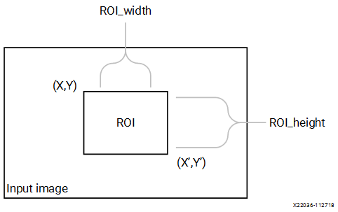
API Syntax
template<int SRC_T, int ROWS, int COLS,int ARCH_TYPE=0,int NPC=1>
void crop(xf::cv::Mat<SRC_T, ROWS, COLS, NPC> & _src_mat,xf::cv::Mat<SRC_T, ROWS, COLS, NPC>  &_dst_mat,xf::cv::Rect_<unsigned int> &roi)
Parameter Descriptions
The following table describes the template and the function parameters.
| Parameter | Description |
|---|---|
| SRC_T | Input pixel type. Only 8-bit, unsigned, 1 and 3 channels are supported (XF_8UC1 and XF_8UC3). |
| ROWS | Maximum height of input and output image. |
| COLS | Maximum width of input and output image. Must be multiple of 8 for 8-pixel operation. |
| ARCH_TYPE | Architecture type. 0 resolves to stream implementation and 1 resolves to memory mapped implementation. |
| NPC | Number of pixels to be processed per cycle. NPC should be power of 2. |
| _src_mat | Input image |
| _dst_mat | Output ROI image |
| roi | ROI is a xf::cv::Rect object that consists of the
top left corner of the rectangle along with the
height and width of the rectangle. |
Resource Utilization
The following table summarizes the resource utilization of crop function in normal mode (NPC=1) for 3 ROIs (480x640, 100x200, 300x300) as generated in the Vivado HLS 2019.1 tool for the Xilinx xczu9eg-ffvb1156-2-i-es2 FPGA.
| Name | Resource Utilization | |
|---|---|---|
| 1 pixel per clock operation | 8 pixel per clock operation | |
| 300 MHz | 150 MHz | |
| BRAM_18K | 6 | 8 |
| DSP48E | 10 | 10 |
| FF | 17482 | 16995 |
| LUT | 16831 | 15305 |
Performance Estimate
The following table summarizes a performance estimate of the kernel in different configurations, generated using Vivado HLS 2019.1 tool for Xczu9eg-ffvb1156-1-i-es1 FPGA to process a grayscale HD (1080x1920) image for 3 ROIs (480x640, 100x200, 300x300).
| Operating Mode | Latency Estimate |
|---|---|
| Max Latency (ms) | |
| 1 pixel operation (300 MHz) | 1.7 |
| 8 pixel operation (150 MHz) | 0.6 |
Multiple ROI Extraction
You can call the xf::cv::crop function multiple times in accel.cpp.
Multiple ROI Extraction Example
void crop_accel(xf::cv::Mat<TYPE, HEIGHT, WIDTH, NPIX> &_src,xf::cv::Mat<TYPE,HEIGHT, WIDTH, NPIX> _dst[NUM_ROI],xf::cv::Rect_<unsigned int> roi[NUM_ROI])
{xf::cv::crop<TYPE, TYPE, HEIGHT, WIDTH, NPIX>(_src, _dst[0],roi[0]); xf::cv::crop<TYPE, TYPE, HEIGHT, WIDTH, NPIX>(_src, _dst[1],roi[1]); xf::cv::crop<TYPE, TYPE, HEIGHT, WIDTH, NPIX>(_src, _dst[2],roi[2]);}
Custom CCA
The custom CCA function takes a binary image as input which contains a
fruit on a conveyer belt (black background) and returns the total fruit pixels
minus defect, total defect pixels and defect image which has the defects marked as
‘255’. This function is a custom made solution for defect detection in fruit, which
ideally works with other pre-processing functions.
The custom CCA algorthm works in two-passes. The first pass includes labelling the background, foreground and defect in forward and reverse raster-scan. The second pass to perform an ‘&’ operation over the forward and reverse partial output data.
API Syntax
template <int HEIGHT, int WIDTH>
void ccaCustom(
uint8_t* in_ptr1,
uint8_t* in_ptr2,
uint8_t* tmp_out_ptr1,
uint8_t* tmp_out_ptr2,
uint8_t* out_ptr,
int& obj_pix,
int& def_pix,
int height,
int width)
Parameter Descriptions
The following table describes the template and the function parameters.
| Parameter | Description |
|---|---|
| HEIGHT | Maximum height of input and output image. |
| WIDTH | Maximum width of input and output image. |
| in_ptr1 | Input 8-bit image pointer for forward pass, binary 8-bit image (‘0’ and ‘255’) |
| in_ptr1 | Input 8-bit image pointer for the parallel computation of reverse pass, binary 8-bit image (‘0’ and ‘255’) |
| tmp_out_ptr1 | 8-bit pointer to store and read from the temporary buffer in DDR for the forward pass. This memory must be allocated before the kernel call. |
| tmp_out_ptr2 | 8-bit pointer to store and read from the temporary buffer in DDR for the reverse pass. This memory must be allocated before the kernel call. |
| out_ptr | Output 8-bit image pointer for the which contains the defects image. Defect pixels are marked as ‘255’. |
| obj_pix | output - no. of object/foreground pixels without the count of defect pixels. |
| def_pix | output - no. of defect pixels in the object/foreground. |
| height | Height of the input image |
| Width | Width of the input image |
Resource Utilization
The following table summarizes the resource utilization for custom CCA, generated using Vitis HLS 2021.1 tool for the xczu9eg-ffvb1156-1-i-es1, to process a FHD (1080x1920) image.
| Operating Mode | Operating Frequency (MHz) | Utilization Estimate | ||||
|---|---|---|---|---|---|---|
| BRAM_18K | DSP_48Es | FF | LUT | CLB | ||
| 1 Pixel | 300 | 10 | 10 | 11166 | 7556 | 1757 |
The following table summarizes the resource utilization for custom CCA, generated using Vitis HLS 2021.1 tool for the xczu9eg-ffvb1156-1-i-es1, to process a 4K image.
| Operating Mode | Operating Frequency (MHz) | Utilization Estimate | ||||
|---|---|---|---|---|---|---|
| BRAM_18K | DSP_48Es | FF | LUT | CLB | ||
| 1 Pixel | 300 | 12 | 10 | 11199 | 7804 | 1748 |
Performance Estimate
The following table summarizes the performance for custom CCA, as generated using Vivado HLS 2019.1 tool for the xczu9eg-ffvb1156-1-i-es1, to process a FHD (1080x1920) image.
| Operating Mode | Latency Estimate |
|---|---|
| Max Latency (ms) | |
| 1 pixel operation (300 MHz) | 14 |
Custom Convolution
The filter2D function performs convolution over an image using a
user-defined kernel.
Convolution is a mathematical operation on two functions f and g, producing a third function, The third function is typically viewed as a modified version of one of the original functions, that gives the area overlap between the two functions to an extent that one of the original functions is translated.
The filter can be unity gain filter or a non-unity gain filter. The filter must be of type XF_16SP. If the co-efficients are floating point, it must be converted into the Qm.n and provided as the input as well as the shift parameter has to be set with the ‘n’ value. Else, if the input is not of floating point, the filter is provided directly and the shift parameter is set to zero.
API Syntax
template<int BORDER_TYPE,int FILTER_WIDTH,int FILTER_HEIGHT, int SRC_T,int DST_T, int ROWS, int COLS,int NPC=1>
void filter2D(xf::cv::Mat<SRC_T, ROWS, COLS, NPC> & _src_mat,xf::cv::Mat<DST_T, ROWS, COLS, NPC> & _dst_mat,short int filter[FILTER_HEIGHT*FILTER_WIDTH],unsigned char _shift)
Parameter Descriptions
The following table describes the template and the function parameters.
| Parameter | Description |
|---|---|
| BORDER_TYPE | Border Type supported is XF_BORDER_CONSTANT |
| FILTER_HEIGHT | Number of rows in the input filter |
| FILTER_WIDTH | Number of columns in the input filter |
| SRC_T | Input pixel type. Only 8-bit, unsigned, 1 and 3 channels are supported (XF_8UC1 and XF_8UC3) |
| DST_T | Output pixel type. 8-bit unsigned single and 3 channels (XF_8UC1, XF_8UC3) and 16-bit signed single and 3 channels (XF_16SC1, XF_16SC3) supported. |
| ROWS | Maximum height of input and output image |
| COLS | Maximum width of input and output image. Must be multiple of 8, for 8 pixel mode. |
| NPC | Number of pixels to be processed per cycle; possible options are XF_NPPC1 and XF_NPPC8 for 1 pixel and 8 pixel operations respectively. |
| _src_mat | Input image |
| _dst_mat | Output image |
| filter | The input filter of any size, provided the dimensions should be an odd number. The filter co-efficients either a 16-bit value or a 16-bit fixed point equivalent value. |
| _shift | The filter must be of type XF_16SP. If the co-efficients are floating point, it must be converted into the Qm.n and provided as the input as well as the shift parameter has to be set with the ‘n’ value. Else, if the input is not of floating point, the filter is provided directly and the shift parameter is set to zero. |
Resource Utilization
The following table summarizes the resource utilization of the kernel in different configurations, generated using Vivado HLS 2019.1 tool for the Xczu9eg-ffvb1156-1-i-es1 FPGA, to process a grayscale HD (1080x1920) image.
| Operating Mode | Filter Size | Operating Frequency (MHz) | Utilization Estimate | ||||
|---|---|---|---|---|---|---|---|
| BRAM_18K | DSP_48Es | FF | LUT | CLB | |||
| 1 Pixel | 3x3 | 300 | 3 | 9 | 1701 | 1161 | 269 |
| 5x5 | 300 | 5 | 25 | 3115 | 2144 | 524 | |
| 8 Pixel | 3x3 | 150 | 6 | 72 | 2783 | 2768 | 638 |
| 5x5 | 150 | 10 | 216 | 3020 | 4443 | 1007 | |
The following table summarizes the resource utilization of the kernel in different configurations, generated using Vivado HLS 2019.1 tool for the Xilinx Xczu9eg-ffvb1156-1-i-es1 FPGA, to process a 4K 3 Channel image.
| Operating Mode | Filter Size | Operating Frequency (MHz) | Utilization Estimate | |||
|---|---|---|---|---|---|---|
| BRAM_18K | DSP_48Es | FF | LUT | |||
| 1 Pixel | 3x3 | 300 | 18 | 27 | 886 | 801 |
| 8 Pixel | 5x5 | 300 | 30 | 75 | 1793 | 1445 |
Performance Estimate
The following table summarizes the performance of the kernel in different configurations, as generated using Vivado HLS 2019.1 tool for the Xczu9eg-ffvb1156-1-i-es1, to process a grayscale HD (1080x1920) image.
| Operating Mode | Operating Frequency (MHz) | Filter Size | Latency Estimate |
|---|---|---|---|
| Max (ms) | |||
| 1 pixel | 300 | 3x3 | 7 |
| 300 | 5x5 | 7.1 | |
| 8 pixel | 150 | 3x3 | 1.86 |
| 150 | 5x5 | 1.86 |
Delay
In image processing pipelines, it is possible that the inputs to a function with FIFO interfaces are not synchronized. That is, the first data packet for first input might arrive a finite number of clock cycles after the first data packet of the second input. If the function has FIFOs at its interface with insufficient depth, this causes the whole design to stall on hardware. To synchronize the inputs, we provide this function to delay the input packet that arrives early, by a finite number of clock cycles.
API Syntax
template<int MAXDELAY, int SRC_T, int ROWS, int COLS,int NPC=1 >
          void delayMat(xf::cv::Mat<SRC_T, ROWS, COLS, NPC> & _src, xf::cv::Mat<SRC_T, ROWS, COLS, NPC> & _dst)
Parameter Descriptions
The table below describes the template and the function parameters.
Parameter Description SRC_T Input and output pixel type ROWS Maximum height of input and output image. COLS Maximum width of input and output image (must be a multiple of 8, for 8 pixel operation) NPC Number of pixels to be processed per cycle; possible options are XF_NPPC1 and XF_NPPC8 for 1 pixel and 8 pixel operations respectively. MAXDELAY Maximum delay that the function is to be instantiated for. _src Input image _dst Output image
Demosaicing
The Demosaicing function converts a single plane Bayer pattern output, from the digital camera sensors to a color image. This function implements an improved bi-linear interpolation technique proposed by Malvar, He, and Cutler.
The above figure shows the Bayer mosaic for color image capture in single-CCD digital cameras.
API Syntax
template<int BFORMAT, int SRC_T, int DST_T, int ROWS, int COLS, int NPC,bool USE_URAM=false>
void demosaicing(xf::cv::Mat<SRC_T, ROWS, COLS, NPC> &src_mat, xf::cv::Mat<DST_T, ROWS, COLS, NPC> &dst_mat)
Parameter Descriptions
The following table describes the template and the function parameters.
| Parameter | Description |
|---|---|
| BFORMAT | Input Bayer pattern. XF_BAYER_BG, XF_BAYER_GB, XF_BAYER_GR, and XF_BAYER_RG are the supported values. |
| SRC_T | Input pixel type. 8-bit, unsigned,1 channel (XF_8UC1) and 16-bit, unsigned, 1 channel (XF_16UC1) are supported. |
| DST_T | Output pixel type. 8-bit, unsigned, 4 channel (XF_8UC4) and 16-bit, unsigned, 4 channel (XF_16UC4) are supported. |
| ROWS | Number of rows in the image being processed. |
| COLS | Number of columns in the image being processed. Must be multiple of 8, in case of 8 pixel mode. |
| NPC | Number of pixels to be processed per cycle; single pixel parallelism (XF_NPPC1), two-pixel parallelism (XF_NPPC2) and four-pixel parallelism (XF_NPPC4) are supported. XF_NPPC4 is not supported with XF_16UC1 pixel type. |
| USE_URAM | Enable to map storage structures to UltraRAM. |
| _src_mat | Input image |
| _dst_mat | Output image |
. rubric:: Resource Utilization
The following table below shows the resource utilization of the Demosaicing function, generated using Vivado HLS 2019.1 version tool for the Xczu9eg-ffvb1156-1-i-es1 FPGA.
| Operating Mode | Operating Frequency (MHz) | Utilization Estimate | ||||
|---|---|---|---|---|---|---|
| BRAM_18K | DSP_48Es | FF | LUT | CLB | ||
| 1 Pixel | 300 | 8 | 0 | 1906 | 1915 | 412 |
| 2 Pixel | 300 | 8 | 0 | 2876 | 3209 | 627 |
| 4 Pixel | 300 | 8 | 0 | 2950 | 3222 | 660 |
The following table shows the resource utilization of the Demosaicing function, generated using Vivado HLS 2019.1 version tool for the xczu7ev-ffvc1156-2-e FPGA.
| Operating Mode | Operating Frequency (MHz) | Utilization Estimate | |||||
|---|---|---|---|---|---|---|---|
| BRAM_18K | URAM | DSP_48Es | FF | LUT | CLB | ||
| 1 Pixel | 300 | 0 | 1 | 0 | 1366 | 1399 | 412 |
Performance Estimate
The following table shows the performance in different configurations, generated using Vivado HLS 2019.1 tool for Xczu9eg-ffvb1156-1-i-es1 to process a 4K (3840x2160) image.
| Operating Mode | Latency Estimate |
|---|---|
| Max Latency (ms) | |
| 1 pixel operation (300 MHz) | 27.82 |
| 2 pixel operation (300 MHz) | 13.9 |
4 pixel operation (300 MHz, 8-bit image only) |
6.95 |
Dilate
During a dilation operation, the current pixel intensity is replaced by the maximum value of the intensity in a nxn neighborhood of the current pixel.

API Syntax
template<int BORDER_TYPE, int TYPE, int ROWS, int COLS,int K_SHAPE,int K_ROWS,int K_COLS, int ITERATIONS, int NPC=1>
void dilate (xf::cv::Mat<TYPE, ROWS, COLS, NPC> & _src, xf::cv::Mat<TYPE, ROWS, COLS, NPC> & _dst,unsigned char _kernel[K_ROWS*K_COLS])
Parameter Descriptions
The following table describes the template and the function parameters.
| Parameter | Description |
|---|---|
| BORDER_TYPE | Border Type supported is XF_BORDER_CONSTANT |
| TYPE | Input and Output pixel type. Only 8-bit, unsigned, 1 and 3 channels are supported (XF_8UC1 and XF_8UC3) |
| ROWS | Maximum height of input and output image. |
| COLS | Maximum width of input and output image (must be multiple of 8, for 8-pixel operation) |
| K_SHAPE | Shape of the kernel . The supported kernel shapes are RECT, CROSS, and ELLIPSE. |
| NPC | Number of pixels to be processed per cycle; possible options are XF_NPPC1 and XF_NPPC8 for 1 pixel and 8 pixel operations respectively. |
| K_ROWS | Height of the kernel. |
| K_COLS | Width of the kernel. |
| ITERATIONS | Number of times the dilation is applied. Currently supporting for Rectangular shape kernel element. |
| _src_mat | Input image |
| _dst_mat | Output image |
| _kernel | Dilation kernel of size K_ROWS * K_COLS. |
Resource Utilization
The following table summarizes the resource utilization of the Dilation function with rectangle shape structuring element in 1 pixel operation and 8 pixel operation, generated using Vivado HLS 2019.1 version tool for the Xczu9eg-ffvb1156-1-i-es1 FPGA for HD (1080X1920) image.
| Name | Resource Utilization | |
|---|---|---|
| 1 pixel per clock operation | 8 pixel per clock operation | |
| 300 MHz | 150 MHz | |
| BRAM_18K | 3 | 6 |
| DSP48E | 0 | 0 |
| FF | 411 | 657 |
| LUT | 392 | 1249 |
| CLB | 96 | 255 |
Performance Estimate
The following table summarizes the resource utilization of the Dilation function with rectangle shape structuring element in 1 pixel operation, generated using Vivado HLS 2019.1 version tool for the Xczu9eg-ffvb1156-1-i-es1 FPGA for 4K 3channel image.
| Name | Resource Utilization |
|---|---|
| 1 pixel per clock operation | |
| 300 MHz | |
| BRAM_18K | 18 |
| DSP48E | 0 |
| FF | 983 |
| LUT | 745 |
| CLB | 186 |
The following table summarizes a performance estimate of the Dilation function for Normal Operation (1 pixel) and Resource Optimized (8 pixel) configurations, generated using Vivado HLS 2019.1 tool for Xczu9eg-ffvb1156-1-i-es1 FPGA.
| Operating Mode | Latency Estimate | |
|---|---|---|
| Min Latency (ms) | Max Latency (ms) | |
| 1 pixel operation (300 MHz) | 7.0 | 7.0 |
| 8 pixel operation (150 MHz) | 1.87 | 1.87 |
Distance Transform Feature Matcher
The distance transform is an operator normally only applied to binary images, where in this case the image must be coded as zero and non-zero pixels as a grayscale image. The result of the transform is a graylevel image that looks similar to the input image, except that the graylevel intensities of points inside foreground regions are changed to show the distance to the closest boundary from each point.
This Xilinx implementation applies 3x3 mask, of distance type DIST_L2 (Euclidean distance), with horizontal/vertical shift cost, a = 0.955, and diagonal shift cost b = 1.3693.
Computing the distance takes two passes, forward and backward. During the forward pass, forward mask is applied, and while the backward pass the backward mask is applied over the forward pass data. In this implementation, it is required to pass a cache memory for the kernel to interact (write while forward pass, read while backward pass). The cache memory must be of image dimensions and of type ap_uint<32>.
API Syntax
template <int IN_PTR, int FW_PTR, int ROWS, int COLS, int USE_URAM>
void distanceTransform(ap_uint<IN_PTR>* _src,
                       float* _dst, ap_uint<FW_PTR>* _fw_pass,
                       int rows, int cols)
Parameter Descriptions
The following table describes template paramters and arguments of the function.
| Parameter | Description |
|---|---|
| IN_PTR | Input pointer width must be ‘8’. |
| FW_PTR | Forward pass data pointer width must be ‘32’. |
| ROWS | Maximum number of rows of the input image that the hardware kernel must be built for. |
| COLS | Maximum number of columns of the input image that the hardware kernel must be built for. |
| USE_URAM | Default is ‘0’. Can be set to ‘1’, if the device has URAM support. |
| _src | Grayscale input image pointer, of ap_uint<8>* type. |
| _dst | The distance image pointer,of type float*. |
| _fw_pass | Forward pass pointer, of type ap_uint<32>. This is used as an intermediary cache, between forward and backward passes. |
| rows | Number of rows in the input image, must be less than ROWS. |
| cols | Number of cols in the input image, must be less than COLS. |
Resource Utilization
The following table summarizes the resource utilization of the kernel in different configurations, generated using Vitis 2020.2 tool, to process a 4K image.
| Operating Mode | Operating Frequency (MHz) | Utilization Estimate | ||||
|---|---|---|---|---|---|---|
| BRAM_18K | DSP_48Es | FF | LUT | CLB | ||
| default | 300 | 22 | 0 | 5129 | 7444 | 1757 |
Performance Estimate
The following table summarizes a performance estimate of the kernel in different configurations, as generated using Vitis 2020.2 tool, to process a 4K image.
| Operating Mode | Operating Frequency (MHz) | Latency Estimate Max (ms) |
|---|---|---|
| default | 200 | 86.249 |
Duplicate
When various functions in a pipeline are implemented by a programmable logic, FIFOs are instantiated between two functions for dataflow processing. When the output from one function is consumed by two functions in a pipeline, the FIFOs need to be duplicated. This function facilitates the duplication process of the FIFOs.
API Syntax
template<int SRC_T, int ROWS, int COLS,int NPC=1>
          void duplicateMat(xf::cv::Mat<SRC_T, ROWS, COLS, NPC> & _src, xf::cv::Mat<SRC_T, ROWS, COLS, NPC> & _dst1,xf::cv::Mat<SRC_T, ROWS, COLS, NPC> & _dst2)
Parameter Descriptions
The table below describes the template and the function parameters.
Paramete r Description SRC_T Input and output pixel type ROWS Maximum height of input and output image. COLS Maximum width of input and output image (must be a multiple of 8, for 8-pixel operation) NPC Number of pixels to be processed per cycle. Possible options are XF_NPPC1 and XF_NPPC8 for 1 pixel and 8 pixel operations respectively. _src Input image _dst1 Duplicate output for _src _dst2 Duplicate output for _src
Erode
The erode function finds the minimum pixel intensity in the NXN
neighborhood of a pixel and replaces the pixel intensity with the
minimum value.

API Syntax
template<int BORDER_TYPE, int TYPE, int ROWS, int COLS,int K_SHAPE,int K_ROWS,int K_COLS, int ITERATIONS, int NPC=1>
void erode (xf::cv::Mat<TYPE, ROWS, COLS, NPC> & _src, xf::cv::Mat<TYPE, ROWS, COLS, NPC> & _dst,unsigned char _kernel[K_ROWS*K_COLS])
Parameter Descriptions
The following table describes the template and the function parameters.
| Parameter | Description |
|---|---|
| BORDER_TYPE | Border type supported is XF_BORDER_CONSTANT |
| TYPE | Input and Output pixel type. Only 8-bit, unsigned, 1 and 3 channels are supported (XF_8UC1 and XF_8UC3) |
| ROWS | Maximum height of input and output image. |
| COLS | Maximum width of input and output image (must be multiple of 8, for 8-pixel operation) |
| K_SHAPE | Shape of the kernel . The supported kernel shapes are RECT,CROSS and ELLIPSE. |
| K_ROWS | Height of the kernel. |
| K_COLS | Width of the kernel. |
| ITERATIONS | Number of times the erosion is applied.Currently supporting for Rectangular shape kernel element. |
| NPC | Number of pixels to be processed per cycle; possible options are XF_NPPC1 and XF_NPPC8 for 1 pixel and 8 pixel operations respectively. |
| _src_mat | Input image |
| _dst_mat | Output image |
| _kernel | Erosion kernel of size K_ROWS * K_COLS. |
Resource Utilization
The following table summarizes the resource utilization of the Erosion function with rectangular shape structuring element generated using Vivado HLS 2019.1 version tool for the Xczu9eg-ffvb1156-1-i-es1 FPGA,for FullHD image(1080x1920).
| Name | Resource Utilization | |
|---|---|---|
| 1 pixel per clock operation | 8 pixel per clock operation | |
| 300 MHz | 150 MHz | |
| BRAM_18K | 3 | 6 |
| DSP48E | 0 | 0 |
| FF | 411 | 657 |
| LUT | 392 | 1249 |
| CLB | 96 | 255 |
The following table summarizes the resource utilization of the Erosion function with rectangular shape structuring element generated using Vivado HLS 2019.1 version tool for the Xczu9eg-ffvb1156-1-i-es1 FPGA,for 4K image with 3channels.
| Name | Resource Utilization |
|---|---|
| 1 pixel per clock operation | |
| 300 MHz | |
| BRAM_18K | 18 |
| DSP48E | 0 |
| FF | 983 |
| LUT | 3745 |
| CLB | 186 |
Performance Estimate
The following table summarizes a performance estimate of the Erosion function for Normal Operation (1 pixel) and Resource Optimized (8 pixel) configurations, generated using Vivado HLS 2019.1 tool for Xczu9eg-ffvb1156-1-i-es1 FPGA.
| Operating Mode | Latency Estimate | |
|---|---|---|
| Min Latency (ms) | Max Latency (ms) | |
| 1 pixel operation (300 MHz) | 7.0 | 7.0 |
| 8 pixel operation (150 MHz) | 1.85 | 1.85 |
FAST Corner Detection
Features from accelerated segment test (FAST) is a corner detection algorithm, that is faster than most of the other feature detectors.
The fast function picks up a pixel in the image and compares the
intensity of 16 pixels in its neighborhood on a circle, called the
Bresenham’s circle. If the intensity of 9 contiguous pixels is found to
be either more than or less than that of the candidate pixel by a given
threshold, then the pixel is declared as a corner. Once the corners are
detected, the non-maximal suppression is applied to remove the weaker
corners.
This function can be used for both still images and videos. The corners are marked in the image. If the corner is found in a particular location, that location is marked with 255, otherwise it is zero.
API Syntax
template<int NMS,int SRC_T,int ROWS, int COLS,int NPC=1>
void fast(xf::cv::Mat<SRC_T, ROWS, COLS, NPC> & _src_mat,xf::cv::Mat<SRC_T, ROWS, COLS, NPC> & _dst_mat,unsigned char _threshold)
Parameter Descriptions
The following table describes the template and the function parameters.
| Parameter | Description |
|---|---|
| NMS | If NMS == 1, non-maximum suppression is applied to detected corners (keypoints). The value should be 0 or 1. |
| SRC_T | Input pixel type. Only 8-bit, unsigned, 1-channel is supported (XF_8UC1) |
| ROWS | Maximum height of input image. |
| COLS | Maximum width of input image (must be a multiple of 8, for 8-pixel operation) |
| NPC | Number of pixels to be processed per cycle; possible options are XF_NPPC1 and XF_NPPC8 for 1 pixel and 8 pixel operations respectively. |
| _src_mat | Input image |
| _dst_mat | Output image. The corners are marked in the image. |
| _threshol d | Threshold on the intensity difference between the center pixel and its neighbors. Usually it is taken around 20. |
Resource Utilization
The following table summarizes the resource utilization of the kernel for different configurations, generated using Vivado HLS 2019.1 for the Xczu9eg-ffvb1156-1-i-es1 FPGA, to process a grayscale HD (1080x1920) image with NMS.
| Name | Resource Utilization | |
|---|---|---|
| 1 pixel per clock operation | 8 pixel per clock operation | |
| 300 MHz | 150 MHz | |
| BRAM_18K | 10 | 20 |
| DSP48E | 0 | 0 |
| FF | 2695 | 7310 |
| LUT | 3792 | 20956 |
| CLB | 769 | 3519 |
Performance Estimate
The following table summarizes the performance of kernel for different configurations, as generated using Vivado HLS 2019.1 tool for the Xczu9eg-ffvb1156-1-i-es1, to process a grayscale HD (1080x1920) image with non-maximum suppression (NMS).
| Operating Mode | Operating Frequency (MHz) | Filter Size | Latency Estimate |
|---|---|---|---|
| Max (ms) | |||
| 1 pixel | 300 | 3x3 | 7 |
| 8 pixel | 150 | 3x3 | 1.86 |
Gaincontrol
The gain control modules improve the overall brightness of the input image. In this module, applying a multiplicative gain (weight) for red and blue channel of the input bayerized image.
API Syntax
template <int BFORMAT, int SRC_T, int ROWS, int COLS, int NPC = 1>
         void gaincontrol(xf::cv::Mat<SRC_T, ROWS, COLS, NPC>& src,
                          xf::cv::Mat<SRC_T, ROWS, COLS, NPC>& dst,
                          unsigned short rgain,
                          unsigned short bgain)
The following table describes the template and the function parameters.
| Parameter | Description |
|---|---|
| BFORMAT | Input Bayer pattern. |
| SRC_T | Input and Output Pixel Type. |
| ROWS | Maximum height of input and output image (Must be multiple of NPC) |
| COLS | Maximum width of input and output image (Must be multiple of NPC) |
| NPC | Number of Pixels to be processed per cycle. |
| src | Input Bayer image |
| dst | Output Bayer image |
| rgain | gain value for red channel in Q9.7 format |
| bgain | gain value for red channel in Q9.7 format |
Resource Utilization
The following table summarizes the resource utilization of the kernel in different configurations, generated using Vivado HLS 2019.2 tool for the Xilinx xc7vx485t-ffg1157-1 FPGA, to process 4K image.
| Operating Mode | Operating Frequency (MHz) |
Utilization Estimate | ||||
|---|---|---|---|---|---|---|
| BRAM_18K | DSP_48Es | FF | LUT | SLICE | ||
| 1 pixel | 300 | 0 | 3 | 233 | 95 | 59 |
| 2 pixel | 300 | 0 | 3 | 235 | 95 | 59 |
Performance Estimate
The following table summarizes a performance estimate of the kernel in different configurations, as generated using Vivado HLS 2019.2 tool for the Xilinx xc7vx485t-ffg1157-1, to process a 4K image.
Operating Mode Operating Frequency
(MHz)
Latency Estimate Max (ms) 1 pixel 300 27.7 2 pixel 300 14.2
Extract Exposure Frames
The extractExposureFrames module returns the Shortexposureframe and Longexposureframe from the input frame using the Digital overlap parameter.
API Syntax
template <int SRC_T, int N_ROWS, int MAX_ROWS, int MAX_COLS, int NPPC = XF_NPPC1, int USE_URAM = 0>
         void extractExposureFrames(xf::cv::Mat<SRC_T, MAX_ROWS * 2, MAX_COLS, NPPC>& _hdrSrc,
                                    xf::cv::Mat<SRC_T, MAX_ROWS, MAX_COLS, NPPC>& _lefSrc,
                                    xf::cv::Mat<SRC_T, MAX_ROWS, MAX_COLS, NPPC>& _sefSrc)
The following table describes the template and the function parameters.
| Parameter | Description |
|---|---|
| SRC_T | Input and Output Pixel Type. |
| N_ROWS | Number of Digital overlap rows between SEF and LEF |
| MAX_ROWS | Maximum height of input and output image (Must be multiple of NPC) |
| MAX_COLS | Maximum width of input and output image (Must be multiple of NPC) |
| NPPC | Number of Pixels to be processed per cycle. |
| USE_URAM | enable to use URAM instead of BRAM in the design. |
| _hdrSrc | Input HDR image |
| _lefSrc | Long exposure frame |
| _sefSrc | Short exposure frame |
Resource Utilization
The following table summarizes the resource utilization of the kernel in different configurations, generated using Vivado HLS 2019.2 tool for the Xilinx xc7vx485t-ffg1157-1 FPGA, to process a HD image.
| Operating Mode | Operating Frequency (MHz) |
Utilization Estimate | ||||
|---|---|---|---|---|---|---|
| BRAM_18K | DSP_48Es | FF | LUT | CLB | ||
| 1 pixel | 300 | 8 | 0 | 408 | 304 | 120 |
Performance Estimate
The following table summarizes a performance estimate of the kernel in different configurations, as generated using Vivado HLS 2019.2 tool for the Xilinx xc7vx485t-ffg1157-1 FPGA, to process a HD image.
| Operating Mode | Operating Frequency (MHz) |
Latency Estimate |
|---|---|---|
| Max (ms) | ||
| 1 pixel | 300 | 14 |
Flip
The Flip function converts input image into output image which is a horizontal flip or vertical flip or both of input image, based on user input.
API Syntax
template <int PTR_WIDTH, int TYPE, int ROWS, int COLS, int NPC>
void flip(ap_uint<PTR_WIDTH>* SrcPtr,
          ap_uint<PTR_WIDTH>* DstPtr,
          int Rows,
          int Cols,
          int Direction)
The following table describes the template and the function parameters.
| Parameter | Description |
|---|---|
| PTR_WIDTH | Pixel Width of Input and Output Pointer |
| TYPE | Input and Output Pixel type |
| ROWS | Maximum height of input and output image (Must be multiple of NPC) |
| COLS | Maximum width of input and output image (Must be multiple of NPC) |
| NPC | Number of Pixels to be processed per cycle. |
| SrcPtr | Input Image pointer. |
| DstPtr | Output Image pointer. |
| Rows | Height of the image |
| Cols | Width of the image |
| Direction | Direction of flip, possible values are horizontal (0), vertical (1) and both (-1) |
Resource Utilization
The following table summarizes the resource utilization in different configurations, generated using Vitis HLS 2021.1 tool for the xczu7ev-ffvc1156-2-e, to process a grayscale 4k (2160x3840) image.
| Operating Mode | Direction of flip | Operating Frequency (MHz) |
Utilization Estimate | ||||
|---|---|---|---|---|---|---|---|
| BRAM_18K | DSP | FF | LUT | URAM | |||
| 1 Pixel | Horizontal | 300 | 12 | 5 | 5888 | 7787 | 0 |
| Vertical | 300 | 12 | 5 | 5888 | 7787 | 0 | |
| Both | 300 | 12 | 5 | 5888 | 7787 | 0 | |
| 4 Pixel | Horizontal | 300 | 16 | 5 | 7180 | 9794 | 0 |
| Vertical | 300 | 16 | 5 | 7180 | 9794 | 0 | |
| Both | 300 | 16 | 5 | 7180 | 9794 | 0 |
The following table summarizes the resource utilization in different configurations, generated using Vitis HLS 2021.1 tool for the xczu7ev-ffvc1156-2-e, to process a 4k (2160x3840) 3 channel image.
| Operating Mode | Direction of flip | Operating Frequency (MHz) |
Utilization Estimate | ||||
|---|---|---|---|---|---|---|---|
| BRAM_18K | DSP | FF | LUT | URAM | |||
| 1 Pixel | Horizontal | 300 | 32 | 5 | 6355 | 9005 | 0 |
| Vertical | 300 | 32 | 5 | 6355 | 9005 | 0 | |
| Both | 300 | 32 | 5 | 6355 | 9005 | 0 | |
| 4 Pixel | Horizontal | 300 | 56 | 5 | 8798 | 15409 | 0 |
| Vertical | 300 | 56 | 5 | 8798 | 15409 | 0 | |
| Both | 300 | 56 | 5 | 8798 | 15409 | 0 |
Performance Estimate
The following table summarizes the resource utilization in different configurations, generated using Vitis HLS 2021.1 tool for the xczu7ev-ffvc1156-2-e, to process a 4k (2160x3840) 3 channel image.
| Operating Mode | Operating Frequency (MHz) |
Latency Estimate |
|---|---|---|
| Max (ms) | ||
| 1 pixel | 300 | 28.5 |
| 4 pixel | 300 | 7.7 |
Gamma Correction
The gammacorrection modules improves the overall brightness of image. The gamma lookuptable is generated using the gamma value and with following equation.

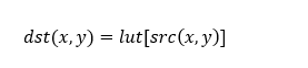
API Syntax
template <int SRC_T, int DST_T, int ROWS, int COLS, int NPC = 1>
void gammacorrection(xf::cv::Mat<SRC_T, ROWS, COLS, NPC>& src,
                     xf::cv::Mat<DST_T, ROWS, COLS, NPC>& dst,
                     unsigned char lut_table[256 * 3])
The following table describes the template and the function parameters.
| Parameter | Description |
|---|---|
| SRC_T | Input Pixel Type. |
| DST_T | Output Pixel Type. |
| ROWS | Maximum height of input and output image (Must be multiple of NPC) |
| COLS | Maximum width of input and output image (Must be multiple of NPC) |
| NPC | Number of Pixels to be processed per cycle. |
| src | Input image |
| dst | Output image |
| lut_table | Lookup table for gamma values.first 256 will be R,next 256 values are G gamma and last 256 values are B values |
Resource Utilization
The following table summarizes the resource utilization of the kernel in different configurations, generated using Vivado HLS 2019.2 tool for the Xilinx xc7vx485t-ffg1157-1 FPGA, to process a 4K image.
| Operating Mode | Operating Frequency (MHz) |
Utilization Estimate | ||||
|---|---|---|---|---|---|---|
| BRAM_18K | DSP_48Es | FF | LUT | CLB | ||
| 1 pixel | 300 | 3 | 0 | 177 | 360 | 120 |
Performance Estimate
The following table summarizes a performance estimate of the kernel in different configurations, as generated using Vivado HLS 2019.2 tool for the Xilinx xc7vx485t-ffg1157-1 FPGA, to process a 4K image.
| Operating Mode | Operating Frequency (MHz) |
Latency Estimate |
|---|---|---|
| Max (ms) | ||
| 1 pixel | 300 | 27.9 |
| 4 pixel | 300 | 7 |
Global Tone Mapping
API Syntax
In order to display HDR images, tone reproduction operators are applied that reduce the dynamic range to that of display device. Global Tone Mapping uses same non-linear mapping function to all pixels throughout the image to reduce the dynamic range.
This implementaion is based on the algorithm proposed by Min H. Kim and Jan Kautz.
template <int SRC_T, int DST_T, int SIN_CHANNEL_IN_TYPE, int SIN_CHANNEL_OUT_TYPE, int ROWS, int COLS, int NPC>
void gtm(xf::cv::Mat<SRC_T, ROWS, COLS, NPC>& src,
                 xf::cv::Mat<DST_T, ROWS, COLS, NPC>& dst,
                 ap_ufixed<16, 4>& mean1,
                 ap_ufixed<16, 4>& mean2,
                 ap_ufixed<16, 4>& L_max1,
                 ap_ufixed<16, 4>& L_max2,
                 ap_ufixed<16, 4>& L_min1,
                 ap_ufixed<16, 4>& L_min2,
                 float c1,
                 float c2)
The following table describes the template and the function parameters.
| Parameter | Description |
|---|---|
| SRC_T | Pixel Width of Input and Output Pointer |
| DST_T | Input and Output Pixel type |
| SIN_CHANNEL_IN_TYPE | Maximum height of input and output image (Must be multiple of NPC) |
| SIN_CHANNEL_OUT_TYPE | Maximum width of input and output image (Must be multiple of NPC) |
| ROWS | Height of the image |
| COLS | Width of the image |
| NPC | Number of Pixels to be processed per cycle. |
| src | Input Image |
| dst | Output Image |
| mean1 | mean of pixel values computed in current frame |
| mean2 | mean of pixel values read by next frame |
| L_max1 | Maximum pixel value computed in current frame |
| L_max2 | Maximum pixel value read by next frame |
| L_min1 | Maximum pixel value computed in current frame |
| L_min2 | Maximum pixel value read by next frame |
| c1 | To retain the details in bright area, default value is 3.0, value ranges from 1 to 7 |
| c2 | Efficiency factor, value ranges from 0.5 to 1 based on output device dynamic range |
Resource Utilization
The following table summarizes the resource utilization in different configurations, generated using Vitis HLS 2021.2 tool for the xczu7ev-ffvc1156-2-e, to process a 4k, 3 channel image.
| Operating Mode | Operating Frequency (MHz) |
Utilization Estimate | ||||
|---|---|---|---|---|---|---|
| BRAM_18K | DSP | FF | LUT | URAM | ||
| 1 Pixel | 300 | 3 | 64 | 14091 | 11566 | 0 |
| 2 Pixel | 300 | 6 | 117 | 22550 | 19232 | 0 |
Performance Estimate
The following table summarizes the resource utilization in different configurations, generated using Vitis HLS 2021.2 tool for the xczu7ev-ffvc1156-2-e, to process a 4k, 3 channel image.
| Operating Mode | Operating Frequency (MHz) |
Latency Estimate |
|---|---|---|
| Max (ms) | ||
| 1 pixel | 300 | 7.53 |
| 2 pixel | 300 | 4.08 |
HDR Merge
HDR Merge module generates the High Dynamic Range (HDR) image from a set of different exposure frames. Usually, image sensors has limited dynamic range and it’s difficult to get HDR image with single image capture. From the sensor, the frames are collected with different exposure times and will get different exposure frames. HDRMerge will generate the HDR frame with those exposure frames. The HDRMerge in RGB domain is complex and expensive interms of latency, because of camera response function. But,in Bayer domain the camera resonse function is linear. The radiance value which passes through the lens of the image sensor is converted into pixel intensity value. The camera response function relates the radiance value to pixel value. The CRF function in
here,

The CRF function f(x) linearly express as
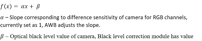
To compute the weight in pixel value domain,
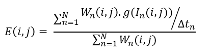
API Syntax
template <int SRC_T, int DST_T, int ROWS, int COLS, int NPC = 1, int NO_EXPS, int W_SIZE>
void Hdrmerge_bayer(xf::cv::Mat<SRC_T, ROWS, COLS, NPC>& _src_mat1,
                xf::cv::Mat<SRC_T, ROWS, COLS, NPC>& _src_mat2,
                xf::cv::Mat<SRC_T, ROWS, COLS, NPC>& _dst_mat,
                short wr_hls[NO_EXPS * NPC * W_SIZE])
The following table describes the template and the function parameters.
| Parameter | Description |
|---|---|
| SRC_T | Input Pixel Type. |
| DST_T | Output Pixel Type. |
| ROWS | Maximum height of input and output image (Must be multiple of NPC) |
| COLS | Maximum width of input and output image (Must be multiple of NPC) |
| NPC | Number of Pixels to be processed per cycle. |
| NO_EXPS | Number exposure frames to be merged in the module |
| W_SIZE | W_SIZE is should be 2 power pixel width. |
| _src_mat1 | Short exposure frame |
| _src_mat2 | Long exposure frame |
| _dst_mat | Output HDR image |
| wr_hls | Lookup table for weight values.computing the weights LUT in host side and passing as input to the function.weight values are Q1.15 |
Resource Utilization
The following table summarizes the resource utilization in different configurations, generated using Vitis HLS 2021.1 tool for the xczu9eg-ffvb1156-2-e, to process a bayer HD image.
| Operating Mode | Pixel Type | Operating Frequency (MHz) |
Utilization Estimate | ||||
|---|---|---|---|---|---|---|---|
| BRAM_18K | DSP | FF | LUT | CLB | |||
| 1 Pixel | 8bit | 300 | 2 | 8 | 5824 | 4886 | 1079 |
| 10bit | 300 | 2 | 8 | 5826 | 4919 | 1034 |
Performance Estimate
The following table summarizes the latency numbers in different configurations, generated using Vitis HLS 2021.1 tool for the xczu9eg-ffvb1156-2-e, to process a HD image.
| Operating Mode | Operating Frequency (MHz) |
Latency Estimate |
|---|---|---|
| Max (ms) | ||
| 1 pixel | 300 | 7.3 |
| 2 pixel | 300 | 3.7 |
Gaussian Filter
The GaussianBlur function applies Gaussian blur on the input image.
Gaussian filtering is done by convolving each point in the input image
with a Gaussian kernel.

Where  ,
, are the mean values and
  ,
,  are the variances in x and y directions respectively. In the
GaussianBlur function, values of , are considered as
zeroes and the values of , are equal.
are the variances in x and y directions respectively. In the
GaussianBlur function, values of , are considered as
zeroes and the values of , are equal.
API Syntax
template<int FILTER_SIZE, int BORDER_TYPE, int SRC_T, int ROWS, int COLS, int NPC =  1>
void GaussianBlur(xf::cv::Mat<SRC_T, ROWS, COLS, NPC> & src, xf::cv::Mat<SRC_T, ROWS, COLS, NPC> & dst, float sigma)
Parameter Descriptions
The following table describes the template and the function parameters.
| Parameter | Description |
|---|---|
| FILTER_SIZE | Filter size. Filter size of 3 (XF_FILTER_3X3), 5 (XF_FILTER_5X5) and 7 (XF_FILTER_7X7) are supported. |
| BORDER_TYPE | Border type supported is XF_BORDER_CONSTANT |
| SRC_T | Input and Output pixel type. Only 8-bit, unsigned, 1 and 3 channels are supported (XF_8UC1 and XF_8UC3) |
| ROWS | Maximum height of input and output image. |
| COLS | Maximum width of input and output image (must be a multiple of 8, for 8-pixel operation) |
| NPC | Number of pixels to be processed per cycle; possible values are XF_NPPC1 and XF_NPPC8 for 1 pixel and 8 pixel operations respectively. |
| src | Input image |
| dst | Output image |
| sigma | Standard deviation of Gaussian filter |
Resource Utilization
The following table summarizes the resource utilization of the Gaussian Filter in different configurations, generated using Vivado HLS 2019.1 version tool for the Xczu9eg-ffvb1156-1-i-es1 FPGA, to progress a grayscale HD (1080x1920) image.
| Operating Mode | Filter Size | Operating Frequency (MHz) | Utilization Estimate | ||||
|---|---|---|---|---|---|---|---|
| BRAM_18K | DSP_48Es | FF | LUT | CLB | |||
| 1 Pixel | 3x3 | 300 | 3 | 17 | 3641 | 2791 | 610 |
| 5x5 | 300 | 5 | 27 | 4461 | 3544 | 764 | |
| 7x7 | 250 | 7 | 35 | 4770 | 4201 | 894 | |
| 8 Pixel | 3x3 | 150 | 6 | 52 | 3939 | 3784 | 814 |
| 5x5 | 150 | 10 | 111 | 5688 | 5639 | 1133 | |
| 7x7 | 150 | 14 | 175 | 7594 | 7278 | 1518 | |
The following table summarizes the resource utilization of the Gaussian Filter in different configurations, generated using Vivado HLS 2019.1 version tool for the Xczu9eg-ffvb1156-1-i-es1 FPGA, to progress a 4K 3 Channel image.
| Operating Mode | Filter Size | Operating Frequency (MHz) |
Utilization Estimate | |||
|---|---|---|---|---|---|---|
| BRAM_18K | DSP_48Es | LUT | CLB | |||
| 1 Pixel | 3x3 | 300 | 18 | 33 | 4835 | 3742 |
| 5x5 | 300 | 30 | 51 | 5755 | 3994 | |
| 7x7 | 300 | 42 | 135 | 8086 | 5422 | |
Performance Estimate
The following table summarizes a performance estimate of the Gaussian Filter in different configurations, as generated using Vivado HLS 2019.1 tool for Xczu9eg-ffvb1156-1-i-es1 FPGA, to process a grayscale HD (1080x1920) image.
| Operating Mode | Filter Size | Latency Estimate |
|---|---|---|
| Max Latency (ms) | ||
| 1 pixel operation (300 MHz) | 3x3 | 7.01 |
| 5x5 | 7.03 | |
| 7x7 | 7.06 | |
| 8 pixel operation (150 MHz) | 3x3 | 1.6 |
| 5x5 | 1.7 | |
| 7x7 | 1.74 |
Gradient Magnitude
The magnitude function computes the magnitude for the images. The
input images are x-gradient and y-gradient images of type 16S. The
output image is of same type as the input image.
For L1NORM normalization, the magnitude computed image is the pixel-wise added image of absolute of x-gradient and y-gradient, as shown below:.

For L2NORM normalization, the magnitude computed image is as follows:

API Syntax
template< int NORM_TYPE ,int SRC_T,int DST_T, int ROWS, int COLS,int NPC=1>
void magnitude(xf::cv::Mat<SRC_T, ROWS, COLS, NPC> & _src_matx,xf::cv::Mat<DST_T, ROWS, COLS, NPC> & _src_maty,xf::cv::Mat<DST_T, ROWS, COLS, NPC> & _dst_mat)
Parameter Descriptions
The following table describes the template and the function parameters.
| Parameter | Description |
|---|---|
| NORM_TYPE | Normalization type can be either L1 or L2 norm. Values are XF_L1NORM or XF_L2NORM |
| SRC_T | Input pixel type. Only 16-bit, signed, 1 channel is supported (XF_16SC1) |
| DST_T | Output pixel type. Only 16-bit, signed,1 channel is supported (XF_16SC1) |
| ROWS | Maximum height of input and output image. |
| COLS | Maximum width of input and output image (must be multiple of 8, for 8-pixel operation) |
| NPC | Number of pixels to be processed per cycle; possible values are XF_NPPC1 and XF_NPPC8 for 1 pixel and 8 pixel operations respectively. |
| _src_matx | First input, x-gradient image. |
| _src_maty | Second input, y-gradient image. |
| _dst_mat | Output, magnitude computed image. |
Resource Utilization
The following table summarizes the resource utilization of the kernel in different configurations, generated using Vivado HLS 2019.1 tool for the Xczu9eg-ffvb1156-1-i-es1 FPGA, to process a grayscale HD (1080x1920) image and for L2 normalization.
| Name | Resource Utilization | |
|---|---|---|
| 1 pixel per clock operation | 8 pixel per clock operation | |
| 300 MHz | 150 MHz | |
| BRAM_18K | 0 | 0 |
| DSP48E | 2 | 16 |
| FF | 707 | 2002 |
| LUT | 774 | 3666 |
| CLB | 172 | 737 |
Performance Estimate
The following table summarizes the performance of the kernel in different configurations, as generated using Vivado HLS 2019.1 tool for the Xczu9eg-ffvb1156-1-i-es1, to process a grayscale HD (1080x1920) image and for L2 normalization.
| Operating Mode | Latency Estimate |
|---|---|
| Max Latency (ms) | |
| 1 pixel operation (300 MHz) | 7.2 |
| 8 pixel operation (150 MHz) | 1.7 |
Gradient Phase
The phase function computes the polar angles of two images. The
input images are x-gradient and y-gradient images of type 16S. The
output image is of same type as the input image.
For radians:

For degrees:

API Syntax
template<int RET_TYPE ,int SRC_T,int DST_T, int ROWS, int COLS,int NPC=1 >
void phase(xf::cv::Mat<SRC_T, ROWS, COLS, NPC> & _src_matx,xf::cv::Mat<DST_T, ROWS, COLS, NPC> & _src_maty,xf::cv::Mat<DST_T, ROWS, COLS, NPC> & _dst_mat)
Parameter Descriptions
The following table describes the template and the function parameters.
| Parameter | Description |
|---|---|
| RET_TYPE | Output format can be either in radians or degrees. Options are XF_RADIANS or XF_DEGREES.
|
| SRC_T | Input pixel type. Only 16-bit, signed, 1 channel is supported (XF_16SC1). |
| DST_T | Output pixel type. Only 16-bit, signed, 1 channel is supported (XF_16SC1) |
| ROWS | Maximum height of input and output image. |
| COLS | Maximum width of input and output image (must be a multiple of 8, for 8-pixel operation) |
| NPC | Number of pixels to be processed per cycle; possible options are XF_NPPC1 and XF_NPPC8 for 1 pixel and 8 pixel operations respectively. |
| _src_matx | First input, x-gradient image. |
| _src_maty | Second input, y-gradient image. |
| _dst_mat | Output, phase computed image. |
Resource Utilization
The following table summarizes the resource utilization of the kernel in different configurations, generated using Vivado HLS 2019.1 tool for the Xczu9eg-ffvb1156-1-i-es1 FPGA, to process a grayscale HD (1080x1920) image.
| Name | Resource Utilization | |
|---|---|---|
| 1 pixel per clock operation | 8 pixel per clock operation | |
| 300 MHz | 150 MHz | |
| BRAM_18K | 6 | 24 |
| DSP48E | 6 | 19 |
| FF | 873 | 2396 |
| LUT | 753 | 3895 |
| CLB | 187 | 832 |
Performance Estimate
The following table summarizes the performance of the kernel in different configurations, as generated using Vivado HLS 2019.1 tool for the Xczu9eg-ffvb1156-1-i-es1, to process a grayscale HD (1080x1920) image.
| Operating Mode | Operating Frequency (MHz) | Latency Estimate (ms) |
|---|---|---|
| 1 pixel | 300 | 7.2 |
| 8 pixel | 150 | 1.7 |
Deviation from OpenCV
In phase implementation, the output is returned in a fixed point format. If XF_RADIANS option is selected, phase API will return result in Q4.12 format. The output range is (0, 2 pi). If XF_DEGREES option is selected, phase API will return result in Q10.6 degrees and output range is (0, 360).
Harris Corner Detection
In order to understand Harris Corner Detection, let us consider a
grayscale image. Sweep a window w(x,y) (with displacements u in
the x-direction and v in the y-direction), I calculates the
variation of intensity w(x,y).

Where:
w(x,y)is the window position at (x,y)I(x,y)is the intensity at (x,y)I(x+u,y+v)is the intensity at the moved window(x+u,y+v).
Since we are looking for windows with corners, we are looking for windows with a large variation in intensity. Hence, we have to maximize the equation above, specifically the term:

Using Taylor expansion:

Expanding the equation and cancelling I(x,y) with -I(x,y):

The above equation can be expressed in a matrix form as:

So, our equation is now:

A score is calculated for each window, to determine if it can possibly contain a corner:


API Syntax
Non-Maximum Suppression:
In non-maximum suppression (NMS) if radius = 1, then the bounding box is 2*r+1 = 3.
In this case, consider a 3x3 neighborhood across the center pixel. If the center pixel is greater than the surrounding pixel, then it is considered a corner. The comparison is made with the surrounding pixels, which are within the radius.
Radius = 1
x-1, y-1 x-1, y x-1, y+1 x, y-1 x, y x, y+1 x+1, y-1 x+1, y x+1, y+1
Threshold:
A threshold=442, 3109 and 566 is used for 3x3, 5x5, and 7x7 filters respectively. This threshold is verified over 40 sets of images. The threshold can be varied, based on the application. The corners are marked in the output image. If the corner is found in a particular location, that location is marked with 255, otherwise it is zero.
template<int FILTERSIZE,int BLOCKWIDTH, int NMSRADIUS,int SRC_T,int ROWS, int COLS,int NPC=1,bool USE_URAM=false>
void cornerHarris(xf::cv::Mat<SRC_T, ROWS, COLS, NPC> & src,xf::cv::Mat<SRC_T, ROWS, COLS, NPC> & dst,uint16_t threshold, uint16_t k)
Parameter Descriptions
The following table describes the template and the function parameters.
| Parameter | Description |
|---|---|
| FILTERSIZE | Size of the Sobel filter. 3, 5, and 7 supported. |
| BLOCKWIDTH | Size of the box filter. 3, 5, and 7 supported. |
| NMSRADIUS | Radius considered for non-maximum suppression. Values supported are 1 and 2. |
| TYPE | Input pixel type. Only 8-bit, unsigned, 1-channel is supported (XF_8UC1). |
| ROWS | Maximum height of input image. |
| COLS | Maximum width of input image (must be multiple of 8, for 8-pixel operation) |
| NPC | Number of pixels to be processed per cycle; possible options are XF_NPPC1 and XF_NPPC8 for 1 pixel and 8 pixel operations respectively. |
| USE_URAM | Enable to map some storage structures to URAM |
| src | Input image |
| dst | Output image. |
| threshold | Threshold applied to the corner measure. |
| k | Harris detector parameter in Q16.16 format. |
Resource Utilization
The following table summarizes the resource utilization of the Harris corner detection in different configurations, generated using Vivado HLS 2019.1 version tool for the Xczu9eg-ffvb1156-1-i-es1 FPGA, to process a grayscale HD (1080x1920) image.
The following table summarizes the resource utilization for Sobel Filter = 3, Box filter=3 and NMS_RADIUS =1.
| Name | Resource Utilization | |
|---|---|---|
| 1 pixel per clock operation | 8 pixel per clock operation | |
| 300 MHz | 150 MHz | |
| BRAM_18K | 33 | 66 |
| DSP48E | 10 | 80 |
| FF | 3254 | 9330 |
| LUT | 3522 | 13222 |
| CLB | 731 | 2568 |
The following table summarizes the resource utilization for Sobel Filter = 3, Box filter=5 and NMS_RADIUS =1.
| Name | Resource Utilization | |
|---|---|---|
| 1 pixel per clock operation | 8 pixel per clock operation | |
| 300 MHz | 150 MHz | |
| BRAM_18K | 45 | 90 |
| DSP48E | 10 | 80 |
| FF | 5455 | 12459 |
| LUT | 5695 | 24594 |
| CLB | 1132 | 4498 |
The following table summarizes the resource utilization for Sobel Filter = 3, Box filter=7 and NMS_RADIUS =1.
| Name | Resource Utilization | |
|---|---|---|
| 1 pixel per clock operation | 8 pixel per clock operation | |
| 300 MHz | 150 MHz | |
| BRAM_18K | 57 | 114 |
| DSP48E | 10 | 80 |
| FF | 8783 | 16593 |
| LUT | 9157 | 39813 |
| CLB | 1757 | 6809 |
The following table summarizes the resource utilization for Sobel Filter = 5, Box filter=3 and NMS_RADIUS =1.
| Name | Resource Utilization | |
|---|---|---|
| 1 pixel per clock operation | 8 pixel per clock operation | |
| 300 MHz | 150 MHz | |
| BRAM_18K | 35 | 70 |
| DSP48E | 10 | 80 |
| FF | 4656 | 11659 |
| LUT | 4681 | 17394 |
| CLB | 1005 | 3277 |
The following table summarizes the resource utilization for Sobel Filter = 5, Box filter=5 and NMS_RADIUS =1.
| Name | Resource Utilization | |
|---|---|---|
| 1 pixel per clock operation | 8 pixel per clock operation | |
| 300 MHz | 150 MHz | |
| BRAM_18K | 47 | 94 |
| DSP48E | 10 | 80 |
| FF | 6019 | 14776 |
| LUT | 6337 | 28795 |
| CLB | 1353 | 5102 |
The following table summarizes the resource utilization for Sobel Filter = 5, Box filter=7 and NMS_RADIUS =1.
| Name | Resource Utilization | |
|---|---|---|
| 1 pixel per clock operation | 8 pixel per clock operation | |
| 300 MHz | 150 MHz | |
| BRAM_18K | 59 | 118 |
| DSP48E | 10 | 80 |
| FF | 9388 | 18913 |
| LUT | 9414 | 43070 |
| CLB | 1947 | 7508 |
The following table summarizes the resource utilization for Sobel Filter = 7, Box filter=3 and NMS_RADIUS =1.
| Name | Resource Utilization | |
|---|---|---|
| 1 pixel per clock operation | 8 pixel per clock operation | |
| 300 MHz | 150 MHz | |
| BRAM_18K | 37 | 74 |
| DSP48E | 11 | 88 |
| FF | 6002 | 13880 |
| LUT | 6337 | 25573 |
| CLB | 1327 | 4868 |
The following table summarizes the resource utilization for Sobel Filter = 7, Box filter=5 and NMS_RADIUS =1.
| Name | Resource Utilization | |
|---|---|---|
| 1 pixel per clock operation | 8 pixel per clock operation | |
| 300 MHz | 150 MHz | |
| BRAM_18K | 49 | 98 |
| DSP48E | 11 | 88 |
| FF | 7410 | 17049 |
| LUT | 8076 | 36509 |
| CLB | 1627 | 6518 |
The following table summarizes the resource utilization for Sobel Filter = 7, Box filter=7 and NMS_RADIUS =1.
| Name | Resource Utilization | |
|---|---|---|
| 1 pixel per clock operation | 8 pixel per clock operation | |
| 300 MHz | 150 MHz | |
| BRAM_18K | 61 | 74 |
| DSP48E | 11 | 88 |
| FF | 10714 | 21137 |
| LUT | 11500 | 51331 |
| CLB | 2261 | 8863 |
The following table summarizes the resource utilization for Sobel Filter = 3, Box filter=3 and NMS_RADIUS =2.
| Name | Resource Utilization | |
|---|---|---|
| 1 pixel | 8 pixel | |
| 300 MHz | 150 MHz | |
| BRAM_18K | 41 | 82 |
| DSP48E | 10 | 80 |
| FF | 5519 | 10714 |
| LUT | 5094 | 16930 |
| CLB | 1076 | 3127 |
The following table summarizes the resource utilization for Sobel Filter = 3, Box filter=5 and NMS_RADIUS =2.
| Name | Resource Utilization | |
|---|---|---|
| 1 pixel | 8 pixel | |
| 300 MHz | 150 MHz | |
| BRAM_18K | 53 | 106 |
| DSP48E | 10 | 80 |
| FF | 6798 | 13844 |
| LUT | 6866 | 28286 |
| CLB | 1383 | 4965 |
The following table summarizes the resource utilization for Sobel Filter = 3, Box filter=7 and NMS_RADIUS =2.
| Name | Resource Utilization | |
|---|---|---|
| 1 pixel | 8 pixel | |
| 300 MHz | 150 MHz | |
| BRAM_18K | 65 | 130 |
| DSP48E | 10 | 80 |
| FF | 10137 | 17977 |
| LUT | 10366 | 43589 |
| CLB | 1940 | 7440 |
The following table summarizes the resource utilization for Sobel Filter = 5, Box filter=3 and NMS_RADIUS =2.
| Name | Resource Utilization | |
|---|---|---|
| 1 pixel | 8 pixel | |
| 300 MHz | 150 MHz | |
| BRAM_18K | 43 | 86 |
| DSP48E | 10 | 80 |
| FF | 5957 | 12930 |
| LUT | 5987 | 21187 |
| CLB | 1244 | 3922 |
The following table summarizes the resource utilization for Sobel Filter = 5, Box filter=5 and NMS_RADIUS =2.
| Name | Resource Utilization | |
|---|---|---|
| 1 pixel | 8 pixel | |
| 300 MHz | 150 MHz | |
| BRAM_18K | 55 | 110 |
| DSP48E | 10 | 80 |
| FF | 5442 | 16053 |
| LUT | 6561 | 32377 |
| CLB | 1374 | 5871 |
The following table summarizes the resource utilization for Sobel Filter = 5, Box filter=7 and NMS_RADIUS =2.
| Name | Resource Utilization | |
|---|---|---|
| 1 pixel | 8 pixel | |
| 300 MHz | 150 MHz | |
| BRAM_18K | 67 | 134 |
| DSP48E | 10 | 80 |
| FF | 10673 | 20190 |
| LUT | 10793 | 46785 |
| CLB | 2260 | 8013 |
The following table summarizes the resource utilization for Sobel Filter = 7, Box filter=3 and NMS_RADIUS =2.
| Name | Resource Utilization | |
|---|---|---|
| 1 pixel | 8 pixel | |
| 300 MHz | 150 MHz | |
| BRAM_18K | 45 | 90 |
| DSP48E | 11 | 88 |
| FF | 7341 | 15161 |
| LUT | 7631 | 29185 |
| CLB | 1557 | 5425 |
The following table summarizes the resource utilization for Sobel Filter = 7, Box filter=5 and NMS_RADIUS =2.
| Name | Resource Utilization | |
|---|---|---|
| 1 pixel | 8 pixel | |
| 300 MHz | 150 MHz | |
| BRAM_18K | 57 | 114 |
| DSP48E | 11 | 88 |
| FF | 8763 | 18330 |
| LUT | 9368 | 40116 |
| CLB | 1857 | 7362 |
The following table summarizes the resource utilization for Sobel Filter = 7, Box filter=7 and NMS_RADIUS =2.
| Name | Resource Utilization | |
|---|---|---|
| 1 pixel | 8 pixel | |
| 300 MHz | 150 MHz | |
| BRAM_18K | 69 | 138 |
| DSP48E | 11 | 88 |
| FF | 12078 | 22414 |
| LUT | 12831 | 54652 |
| CLB | 2499 | 9628 |
Resource Utilization with URAM enable
This section summarizes the resource utilization of the Harris corner detection in different configurations, generated using Vivado HLS 2019.1 version tool for the xczu7ev-ffvc1156-2-e FPGA, to process a grayscale 4K (3840X2160) image.
The following table summarizes the resource utilization for Sobel Filter = 3, Box filter=3 and NMS_RADIUS =1.
| Name | Resource Utilization | |
|---|---|---|
| 1 pixel | 8 pixel | |
| 300 MHz | 150 MHz | |
| BRAM_18K | 12 | 12 |
| URAM | 4 | 21 |
| DSP48E | 10 | 80 |
| FF | 5306 | 11846 |
| LUT | 3696 | 13846 |
The following table summarizes the resource utilization for Sobel Filter = 3, Box filter=5 and NMS_RADIUS =1.
| Name | Resource Utilization | |
|---|---|---|
| 1 pixel | 8 pixel | |
| 300 MHz | 150 MHz | |
| BRAM_18K | 12 | 12 |
| URAM | 7 | 30 |
| DSP48E | 10 | 80 |
| FF | 7625 | 13899 |
| LUT | 5596 | 27136 |
The following table summarizes the resource utilization for Sobel Filter = 3, Box filter=7 and NMS_RADIUS =1.
| Name | Resource Utilization | |
|---|---|---|
| 1 pixel | 8 pixel | |
| 300 MHz | 150 MHz | |
| BRAM_18K | 12 | 12 |
| URAM | 7 | 42 |
| DSP48E | 10 | 80 |
| FF | 12563 | 19919 |
| LUT | 8816 | 39087 |
The following table summarizes the resource utilization for Sobel Filter = 5, Box filter=3 and NMS_RADIUS =1.
| Name | Resource Utilization | |
|---|---|---|
| 1 pixel | 8 pixel | |
| 300 MHz | 150 MHz | |
| BRAM_18K | 12 | 12 |
| URAM | 4 | 23 |
| DSP48E | 10 | 80 |
| FF | 6689 | 15022 |
| LUT | 4506 | 18719 |
The following table summarizes the resource utilization for Sobel Filter = 5, Box filter=5 and NMS_RADIUS =1.
| Name | Resource Utilization | |
|---|---|---|
| 1 pixel | 8 pixel | |
| 300 MHz | 150 MHz | |
| BRAM_18K | 12 | 12 |
| URAM | 7 | 32 |
| DSP48E | 10 | 80 |
| FF | 9050 | 17063 |
| LUT | 6405 | 31992 |
The following table summarizes the resource utilization for Sobel Filter = 5, Box filter=7 and NMS_RADIUS =1.
| Name | Resource Utilization | |
|---|---|---|
| 1 pixel | 8 pixel | |
| 300 MHz | 150 MHz | |
| BRAM_18K | 12 | 12 |
| URAM | 7 | 44 |
| DSP48E | 10 | 80 |
| FF | 13946 | 23116 |
| LUT | 9626 | 44738 |
The following table summarizes the resource utilization for Sobel Filter = 7, Box filter=3 and NMS_RADIUS =1.
| Name | Resource Utilization | |
|---|---|---|
| 1 pixel | 8 pixel | |
| 300 MHz | 150 MHz | |
| BRAM_18K | 12 | 12 |
| URAM | 4 | 25 |
| DSP48E | 11 | 88 |
| FF | 8338 | 17378 |
| LUT | 6151 | 24844 |
The following table summarizes the resource utilization for Sobel Filter = 7, Box filter=5 and NMS_RADIUS =1.
| Name | Resource Utilization | |
|---|---|---|
| 1 pixel | 8 pixel | |
| 300 MHz | 150 MHz | |
| BRAM_18K | 12 | 12 |
| URAM | 7 | 34 |
| DSP48E | 11 | 88 |
| FF | 10497 | 19457 |
| LUT | 7858 | 39762 |
The following table summarizes the resource utilization for Sobel Filter = 7, Box filter=7 and NMS_RADIUS =1.
| Name | Resource Utilization | |
|---|---|---|
| 1 pixel | 8 pixel | |
| 300 MHz | 150 MHz | |
| BRAM_18K | 12 | 12 |
| URAM | 7 | 46 |
| DSP48E | 11 | 88 |
| FF | 15393 | 25450 |
| LUT | 11080 | 50662 |
The following table summarizes the resource utilization for Sobel Filter = 3, Box filter=3 and NMS_RADIUS =2.
| Name | Resource Utilization | |
|---|---|---|
| 1 pixel | 8 pixel | |
| 300 MHz | 150 MHz | |
| BRAM_18K | 20 | 20 |
| URAM | 4 | 21 |
| DSP48E | 10 | 80 |
| FF | 6286 | 13441 |
| LUT | 4704 | 18072 |
The following table summarizes the resource utilization for Sobel Filter = 3, Box filter=5 and NMS_RADIUS =2.
| Name | Resource Utilization | |
|---|---|---|
| 1 pixel | 8 pixel | |
| 300 MHz | 150 MHz | |
| BRAM_18K | 20 | 20 |
| URAM | 7 | 30 |
| DSP48E | 10 | 80 |
| FF | 8626 | 15498 |
| LUT | 6606 | 31371 |
The following table summarizes the resource utilization for Sobel Filter = 3, Box filter=7 and NMS_RADIUS =2.
| Name | Resource Utilization | |
|---|---|---|
| 1 pixel | 8 pixel | |
| 300 MHz | 150 MHz | |
| BRAM_18K | 20 | 20 |
| URAM | 7 | 42 |
| DSP48E | 10 | 80 |
| FF | 13543 | 21522 |
| LUT | 9853 | 43301 |
The following table summarizes the resource utilization for Sobel Filter = 5, Box filter=3 and NMS_RADIUS =2.
| Name | Resource Utilization | |
|---|---|---|
| 1 pixel | 8 pixel | |
| 300 MHz | 150 MHz | |
| BRAM_18K | 20 | 20 |
| URAM | 4 | 23 |
| DSP48E | 10 | 80 |
| FF | 7670 | 16750 |
| LUT | 5513 | 22854 |
The following table summarizes the resource utilization for Sobel Filter = 5, Box filter=5 and NMS_RADIUS =2.
| Name | Resource Utilization | |
|---|---|---|
| 1 pixel | 8 pixel | |
| 300 MHz | 150 MHz | |
| BRAM_18K | 20 | 20 |
| URAM | 7 | 32 |
| DSP48E | 10 | 80 |
| FF | 9712 | 18793 |
| LUT | 7338 | 36136 |
The following table summarizes the resource utilization for Sobel Filter = 5, Box filter=7 and NMS_RADIUS =2.
| Name | Resource Utilization | |
|---|---|---|
| 1 pixel | 8 pixel | |
| 300 MHz | 150 MHz | |
| BRAM_18K | 20 | 20 |
| URAM | 7 | 44 |
| DSP48E | 10 | 80 |
| FF | 14650 | 24846 |
| LUT | 10558 | 48866 |
The following table summarizes the resource utilization for Sobel Filter = 7, Box filter=3 and NMS_RADIUS =2.
| Name | Resource Utilization | |
|---|---|---|
| 1 pixel | 8 pixel | |
| 300 MHz | 150 MHz | |
| BRAM_18K | 20 | 20 |
| URAM | 4 | 25 |
| DSP48E | 11 | 88 |
| FF | 9562 | 19101 |
| LUT | 7405 | 29986 |
The following table summarizes the resource utilization for Sobel Filter = 7, Box filter=5 and NMS_RADIUS =2.
| Name | Resource Utilization | |
|---|---|---|
| 1 pixel | 8 pixel | |
| 300 MHz | 150 MHz | |
| BRAM_18K | 20 | 20 |
| URAM | 7 | 34 |
| DSP48E | 11 | 88 |
| FF | 11751 | 21180 |
| LUT | 9254 | 44024 |
The following table summarizes the resource utilization for Sobel Filter = 7, Box filter=7 and NMS_RADIUS =2.
| Name | Resource Utilization | |
|---|---|---|
| 1 pixel | 8 pixel | |
| 300 MHz | 150 MHz | |
| BRAM_18K | 20 | 20 |
| URAM | 7 | 46 |
| DSP48E | 11 | 88 |
| FF | 16723 | 27156 |
| LUT | 12474 | 54858 |
Performance Estimate
The following table summarizes a performance estimate of the Harris corner detection in different configurations, as generated using Vivado HLS 2019.1 tool for Xilinx Xczu9eg-ffvb1156-1-i-es1 FPGA, to process a grayscale HD (1080x1920) image.
| Operating Mode | Operating Frequency (MHz) |
Configuration | Latency Estimate | ||
|---|---|---|---|---|---|
| Sobel | Box | NMS Radius | Latency(In ms) | ||
| 1 pixel | 300 MHz | 3 | 3 | 1 | 7 |
| 1 pixel | 300 MHz | 3 | 5 | 1 | 7.1 |
| 1 pixel | 300 MHz | 3 | 7 | 1 | 7.1 |
| 1 pixel | 300 MHz | 5 | 3 | 1 | 7.2 |
| 1 pixel | 300 MHz | 5 | 5 | 1 | 7.2 |
| 1 pixel | 300 MHz | 5 | 7 | 1 | 7.2 |
| 1 pixel | 300 MHz | 7 | 3 | 1 | 7.22 |
| 1 pixel | 300 MHz | 7 | 5 | 1 | 7.22 |
| 1 pixel | 300 MHz | 7 | 7 | 1 | 7.22 |
| 8 pixel | 150 MHz | 3 | 3 | 1 | 1.7 |
| 8 pixel | 150 MHz | 3 | 5 | 1 | 1.7 |
| 8 pixel | 150 MHz | 3 | 7 | 1 | 1.7 |
| 8 pixel | 150 MHz | 5 | 3 | 1 | 1.71 |
| 8 pixel | 150 MHz | 5 | 5 | 1 | 1.71 |
| 8 pixel | 150 MHz | 5 | 7 | 1 | 1.71 |
| 8 pixel | 150 MHz | 7 | 3 | 1 | 1.8 |
| 8 pixel | 150 MHz | 7 | 5 | 1 | 1.8 |
| 8 pixel | 150 MHz | 7 | 7 | 1 | 1.8 |
| 1 pixel | 300 MHz | 3 | 3 | 2 | 7.1 |
| 1 pixel | 300 MHz | 3 | 5 | 2 | 7.1 |
| 1 pixel | 300 MHz | 3 | 7 | 2 | 7.1 |
| 1 pixel | 300 MHz | 5 | 3 | 2 | 7.21 |
| 1 pixel | 300 MHz | 5 | 5 | 2 | 7.21 |
| 1 pixel | 300 MHz | 5 | 7 | 2 | 7.21 |
| 1 pixel | 300 MHz | 7 | 3 | 2 | 7.22 |
| 1 pixel | 300 MHz | 7 | 5 | 2 | 7.22 |
| 1 pixel | 300 MHz | 7 | 7 | 2 | 7.22 |
| 8 pixel | 150 MHz | 3 | 3 | 2 | 1.8 |
| 8 pixel | 150 MHz | 3 | 5 | 2 | 1.8 |
| 8 pixel | 150 MHz | 3 | 7 | 2 | 1.8 |
| 8 pixel | 150 MHz | 5 | 3 | 2 | 1.81 |
| 8 pixel | 150 MHz | 5 | 5 | 2 | 1.81 |
| 8 pixel | 150 MHz | 5 | 7 | 2 | 1.81 |
| 8 pixel | 150 MHz | 7 | 3 | 2 | 1.9 |
| 8 pixel | 150 MHz | 7 | 5 | 2 | 1.91 |
| 8 pixel | 150 MHz | 7 | 7 | 2 | 1.92 |
Deviation from OpenCV
In Vitis Vision, thresholding and NMS are included, but in OpenCV they are not included. In Vitis Vision, all the blocks are implemented in fixed point. Whereas, in OpenCV, all the blocks are implemented in floating point.
Histogram Computation
calcHist function computes the histogram of given input image.
API Syntax
template<int SRC_T,int ROWS, int COLS,int NPC=1>
void calcHist(xf::cv::Mat<SRC_T, ROWS, COLS, NPC> & _src, uint32_t *histogram)
Parameter Descriptions
The following table describes the template and the function parameters.
| Parameter | Description |
|---|---|
| SRC_T | Input pixel type. Only 8-bit, unsigned, 1 and 3 channels are supported (XF_8UC1 and XF_8UC3) |
| ROWS | Maximum height of input and output image. |
| COLS | Maximum width of input and output image (must be multiple of 8, for 8-pixel operation) |
| NPC | Number of pixels to be processed per cycle |
| _src | Input image |
| histogram | Output array of 256 elements |
Resource Utilization
The following table summarizes the resource utilization of the calcHist function for Normal Operation (1 pixel) and Resource Optimized (8 pixel) configurations, generated using Vivado HLS 2019.1 version tool for the Xczu9eg-ffvb1156-1-i-es1 FPGA at 300 MHz for 1 pixel case and at 150 MHz for 8 pixel mode.
| Name | Resource Utilization | |
|---|---|---|
| Normal Operation (1 pixel) | Resource Optimized (8 pixel) | |
| BRAM_18K | 2 | 16 |
| DSP48E | 0 | 0 |
| FF | 196 | 274 |
| LUT | 240 | 912 |
| CLB | 57 | 231 |
The following table summarizes the resource utilization of the calcHist function for Normal Operation (1 pixel), generated using Vivado HLS 2019.1 version tool for the Xczu9eg-ffvb1156-1-i-es1 FPGA at 300 MHz for 1 pixel case for 4K image 3 channel.
| Name | Resource Utilization |
|---|---|
| Normal Operation (1 pixel) | |
| BRAM_18K | 8 |
| DSP48E | 0 |
| FF | 381 |
| LUT | 614 |
| CLB | 134 |
Performance Estimate
The following table summarizes a performance estimate of the calcHist function for Normal Operation (1 pixel) and Resource Optimized (8 pixel) configurations, generated using Vivado HLS 2019.1 version tool for the Xczu9eg-ffvb1156-1-i-es1 FPGA at 300 MHz for 1 pixel and 150 MHz for 8 pixel mode.
| Operating Mode | Latency Estimate |
|---|---|
| Max Latency (ms) | |
| 1 pixel operation (300 MHz) | 6.9 |
| 8 pixel operation (150 MHz) | 1.7 |
Histogram Equalization
The equalizeHist function performs histogram equalization on input
image or video. It improves the contrast in the image, to stretch out
the intensity range. This function maps one distribution (histogram) to
another distribution (a wider and more uniform distribution of intensity
values), so the intensities are spread over the whole range.
For histogram H[i], the cumulative distribution H’[i] is given as:

The intensities in the equalized image are computed as:

API Syntax
template<int SRC_T, int ROWS, int COLS, int NPC = 1>
void equalizeHist(xf::cv::Mat<SRC_T, ROWS, COLS, NPC> & _src,xf::cv::Mat<SRC_T, ROWS, COLS, NPC> & _src1,xf::cv::Mat<SRC_T, ROWS, COLS, NPC> & _dst)
Parameter Descriptions
The following table describes the template and the function parameters.
| Parameter | Description |
|---|---|
| SRC_T | Input and output pixel type. Only 8-bit, unsigned, 1 channel is supported (XF_8UC1) |
| ROWS | Maximum height of input and output image. |
| COLS | Maximum width of input and output image (must be a multiple of 8, for 8-pixel operation) |
| NPC | Number of pixels to be processed per cycle |
| _src | Input image |
| _src1 | Input image |
| _dst | Output image |
Resource Utilization
The following table summarizes the resource utilization of the equalizeHist function for Normal Operation (1 pixel) and Resource Optimized (8 pixel) configurations, generated using Vivado HLS 2019.1 version tool for the Xczu9eg-ffvb1156-1-i-es1 FPGA at 300 MHz for 1 pixel and 150 MHz for 8 pixel mode.
| Operating Mode | Operating Frequency (MHz) | Utilization Estimate | ||||
|---|---|---|---|---|---|---|
| BRAM_18K | DSP_48Es | FF | LUT | CLB | ||
| 1 pixel | 300 | 4 | 5 | 3492 | 1807 | 666 |
| 8 pixel | 150 | 25 | 5 | 3526 | 2645 | 835 |
Performance Estimate
The following table summarizes a performance estimate of the equalizeHist function for Normal Operation (1 pixel) and Resource Optimized (8 pixel) configurations, generated using Vivado HLS 2019.1version tool for the Xczu9eg-ffvb1156-1-i-es1 FPGA at 300 MHz for 1 pixel and 150 MHz for 8 pixel mode.
| Operating Mode | Latency Estimate |
|---|---|
| Max (ms) | |
| 1 pixel per clock operation | 13.8 |
| 8 pixel per clock operation | 3.4 |
HOG
The Histogram of Oriented Gradients (HOG) is a feature descriptor used in computer vision for the purpose of object detection. The feature descriptors produced from this approach is widely used in the pedestrian detection.
The technique counts the occurrences of gradient orientation in localized portions of an image. HOG is computed over a dense grid of uniformly spaced cells and normalized over overlapping blocks, for improved accuracy. The concept behind HOG is that the object appearance and shape within an image can be described by the distribution of intensity gradients or edge direction.
Both RGB and gray inputs are accepted to the function. In the RGB mode, gradients are computed for each plane separately, but the one with the higher magnitude is selected. With the configurations provided, the window dimensions are 64x128, block dimensions are 16x16.
API Syntax
template<int WIN_HEIGHT, int WIN_WIDTH, int WIN_STRIDE, int BLOCK_HEIGHT, int BLOCK_WIDTH, int CELL_HEIGHT, int CELL_WIDTH, int NOB, int DESC_SIZE, int IMG_COLOR, int OUTPUT_VARIANT, int SRC_T, int DST_T, int ROWS, int COLS, int NPC = XF_NPPC1,bool USE_URAM=false>
void HOGDescriptor(xf::cv::Mat<SRC_T, ROWS, COLS, NPC> &_in_mat, xf::cv::Mat<DST_T, 1, DESC_SIZE, NPC> &_desc_mat);
Parameter Descriptions
The following table describes the template parameters.
| Parameters | Description |
|---|---|
| WIN_HEIGHT | The number of pixel rows in the window. This must be a multiple of 8 and should not exceed the number of image rows. |
| WIN_WIDTH | The number of pixel cols in the window. This must be a multiple of 8 and should not exceed the number of image columns. |
| WIN_STRIDE | The pixel stride between two adjacent windows. It is fixed at 8. |
| BLOCK_HEIGHT | Height of the block. It is fixed at 16. |
| BLOCK_WIDTH | Width of the block. It is fixed at 16. |
| CELL_HEIGHT | Number of rows in a cell. It is fixed at 8. |
| CELL_WIDTH | Number of cols in a cell. It is fixed at 8. |
| NOB | Number of histogram bins for a cell. It is fixed at 9 |
| DESC_SIZE | The size of the output descriptor. |
| IMG_COLOR | The type of the image, set as either XF_GRAY or XF_RGB |
| OUTPUT_VARIE NT | Must be either XF_HOG_RB or XF_HOG_NRB |
| SRC_T | Input pixel type. Must be either XF_8UC1 or XF_8UC4, for gray and color respectively. |
| DST_T | Output descriptor type. Must be XF_32UC1. |
| ROWS | Number of rows in the image being processed. |
| COLS | Number of columns in the image being processed. |
| NPC | Number of pixels to be processed per cycle; this function supports only XF_NPPC1 or 1 pixel per cycle operations. |
| USE_URAM | Enable to map UltraRAM instead of BRAM for some storage structures. |
The following table describes the function parameters.
| Parameters | Description |
|---|---|
| _in_mat | Input image, of xf::cv::Mat type |
| _desc_mat | Output descriptors, of xf::cv::Mat type |
Where,
- NO is normal operation (single pixel processing)
- RB is repetitive blocks (descriptor data are written window wise)
- NRB is non-repetitive blocks (descriptor data are written block wise, in order to reduce the number of writes).
Note: In the RB mode, the block data is written to the memory taking the overlap windows into consideration. In the NRB mode, the block data is written directly to the output stream without consideration of the window overlap. In the host side, the overlap must be taken care.
Resource Utilization
The following table shows the resource utilization of HOGDescriptor
function for normal operation (1 pixel) mode as generated in Vivado HLS
2019.1 version tool for the part Xczu9eg-ffvb1156-1-i-es1 at 300 MHz to
process an image of 1920x1080 resolution.
| Resource | Utilization (at 300 MHz) of 1 pixel operation | |||
|---|---|---|---|---|
| NRB | RB | |||
| Gray | RGB | Gray | RGB | |
| BRAM_18K | 43 | 49 | 171 | 177 |
| DSP48E | 34 | 46 | 36 | 48 |
| FF | 15365 | 15823 | 15205 | 15663 |
| LUT | 12868 | 13267 | 13443 | 13848 |
The following table shows the resource utilization of HOGDescriptor
function for normal operation (1 pixel) mode as generated in Vivado HLS 2019.1
version tool for the part xczu7ev-ffvc1156-2-e at 300 MHz to process an
image of 1920x1080 resolution with UltraRAM enabled.
| Resource | Utilization (at 300 MHz) of 1 pixel operation | |||
|---|---|---|---|---|
| NRB | RB | |||
| Gray | RGB | Gray | RGB | |
| BRAM_18K | 10 | 12 | 18 | 20 |
| URAM | 15 | 15 | 15 | 17 |
| DSP48E | 34 | 46 | 36 | 48 |
| FF | 17285 | 17917 | 18270 | 18871 |
| LUT | 12409 | 12861 | 12793 | 13961 |
Performance Estimate
The following table shows the performance estimates of HOGDescriptor() function for different configurations as generated in Vivado HLS 2019.1 version tool for the part Xczu9eg-ffvb1156-1-i-es1 to process an image of 1920x1080p resolution.
| Operating Mode | Operating Frequency (MHz) | Latency Estimate | |
|---|---|---|---|
| Min (ms) | Max (ms) | ||
| NRB-Gray | 300 | 6.98 | 8.83 |
| NRB-RGBA | 300 | 6.98 | 8.83 |
| RB-Gray | 300 | 176.81 | 177 |
| RB-RGBA | 300 | 176.81 | 177 |
Deviations from OpenCV
Listed below are the deviations from the OpenCV:
Border care
The border care that OpenCV has taken in the gradient computation is BORDER_REFLECT_101, in which the border padding will be the neighboring pixels’ reflection. Whereas, in the Xilinx implementation, BORDER_CONSTANT (zero padding) was used for the border care.
Gaussian weighing
The Gaussian weights are multiplied on the pixels over the block, that is a block has 256 pixels, and each position of the block are multiplied with its corresponding Gaussian weights. Whereas, in the HLS implementation, gaussian weighing was not performed.
Cell-wise interpolation The magnitude values of the pixels are distributed across different cells in the blocks but on the corresponding bins.
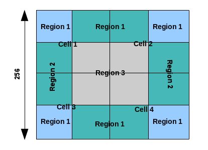 Pixels in the region 1 belong only to its corresponding cells, but
the pixels in region 2 and 3 are interpolated to the adjacent 2 cells
and 4 cells respectively. This operation was not performed in the HLS
implementation.
Pixels in the region 1 belong only to its corresponding cells, but
the pixels in region 2 and 3 are interpolated to the adjacent 2 cells
and 4 cells respectively. This operation was not performed in the HLS
implementation.Output handling
The output of the OpenCV will be in the column major form. In the HLS implementation, output will be in the row major form. Also, the feature vector will be in the fixed point type Q0.16 in the HLS implementation, while in the OpenCV it will be in floating point.
Limitations
- The configurations are limited to Dalal’s implementation
- Image height and image width must be a multiple of cell height and cell width respectively.
HoughLines
The HoughLines function here is equivalent to HoughLines Standard in
OpenCV. The HoughLines function is used to detect straight lines in
a binary image. To apply the Hough transform, edge detection
preprocessing is required. The input to the Hough transform is an edge
detected binary image. For each point (xi,yi) in a binary image, we
define a family of lines that go through the point as:
rho= xi cos(theta) + yi sin(theta)
Each pair of (rho,theta) represents a line that passes through the point
(xi,yi). These (rho,theta) pairs of this family of lines passing through
the point form a sinusoidal curve in (rho,theta) plane. If the sinusoids
of N different points intersect in the (rho,theta) plane, then that
intersection (rho1, theta1) represents the line that passes through
these N points. In the HoughLines function, an accumulator is used
to keep the count (also called voting) of all the intersection points in
the (rho,theta) plane. After voting, the function filters spurious lines
by performing thinning, that is, checking if the center vote value is
greater than the neighborhood votes and threshold, then making that
center vote as valid and other wise making it zero. Finally, the
function returns the desired maximum number of lines (LINESMAX) in
(rho,theta) form as output.
The design assumes the origin at the center of the image i.e at (Floor(COLS/2), Floor(ROWS/2)). The ranges of rho and theta are:
theta = [0, pi)
rho=[-DIAG/2, DIAG/2), where DIAG = cvRound{SquareRoot( (COLS*COLS) + (ROWS*ROWS))}
For ease of use, the input angles THETA, MINTHETA and MAXTHETA are taken in degrees, while the output theta is in radians. The angle resolution THETA is declared as an integer, but treated as a value in Q6.1 format (that is, THETA=3 signifies that the resolution used in the function is 1.5 degrees). When the output (rho, ? theta) is used for drawing lines, you should be aware of the fact that origin is at the center of the image.
API Syntax
template<unsigned int RHO,unsigned int THETA,int MAXLINES,int DIAG,int MINTHETA,int MAXTHETA,int SRC_T, int ROWS, int COLS,int NPC>
void HoughLines(xf::cv::Mat<SRC_T, ROWS, COLS, NPC> & _src_mat,float outputrho[MAXLINES],float outputtheta[MAXLINES],short threshold,short linesmax)
Parameter Descriptions
The following table describes the template and the function parameters.
| Parameter | Description |
|---|---|
| RHO | Distance resolution of the accumulator in pixels. |
| THETA | Angle resolution of the accumulator in degrees and Q6.1 format. |
| MAXLINES | Maximum number of lines to be detected |
| MINTHETA | Minimum angle in degrees to check lines. |
| MAXTHETA | Maximum angle in degrees to check lines |
| DIAG | Diagonal of the image. It should be cvRound(sqrt(rows*rows + cols*cols)/RHO). |
| SRC_T | Input Pixel Type. Only 8-bit, unsigned, 1-channel is supported (XF_8UC1). |
| ROWS | Maximum height of input image |
| COLS | Maximum width of input image |
| NPC | Number of Pixels to be processed per cycle; Only single pixel supported XF_NPPC1. |
| _src_mat | Input image should be 8-bit, single-channel binary image. |
| outputrho | Output array of rho values. rho is the distance from the coordinate origin (center of the image). |
| outputthe ta | Output array of theta values. Theta is the line rotation angle in radians. |
| threshold | Accumulator threshold parameter. Only those lines are returned that get enough votes (>threshold). |
| linesmax | Maximum number of lines. |
Resource Utilization
The table below shows the resource utilization of the kernel for different configurations, generated using Vivado HLS 2019.1 version tool for the Xczu9eg-ffvb1156-1-i-es1 to process a grayscale HD (1080x1920) image for 512 lines.
| Name | Resource Utilization |
|---|---|
| THETA=1, RHO=1 | |
| BRAM_18K | 542 |
| DSP48E | 10 |
| FF | 60648 |
| LUT | 56131 |
Performance Estimate
The following table shows the performance of kernel for different configurations, generated using Vivado HLS 2019.1 version tool for the Xczu9eg-ffvb1156-1-i-es1 to process a grayscale HD (1080x1920) image for 512 lines.
| Operating Mode | Operating Frequency (MHz) | Latency Estimate |
|---|---|---|
| Max (ms) | ||
| THETA=1, RHO=1 | 300 | 12.5 |
Preprocessing for Deep Neural Networks
The input image are typically pre-processed before being fed for inference of different deep neural networks (DNNs). The preProcess function provides various modes to perform various preprocessing operations. The preprocessing function\(\ f(x\)) can be described using below equations.
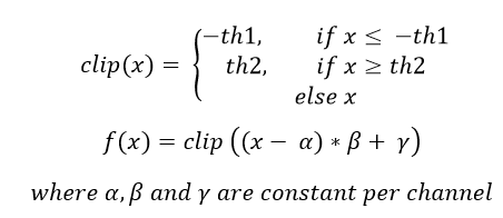
The preProcess function supports operating modes presented in the below table:
Op Code Operation Description 0 Mean subtraction 1 Scale and clip 2 Clipping 3 Scale and bias 4 Scale and bias with mean subtraction 5 Complete operation

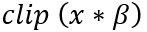

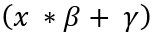
API Syntax
template <int INPUT_PTR_WIDTH_T,int OUTPUT_PTR_WIDTH_T, int T_CHANNELS_T, int CPW_T, int ROWS_T, int COLS_T, int NPC_T, bool PACK_MODE_T, int WX_T, int WA_T, int WB_T, int WY_T, int WO_T, int FX_T, int FA_T, int FB_T, int FY_T,int FO_T, bool SIGNED_IN_T, int OPMODE_T>

void preProcess(hls::stream<ap_uint<INPUT_PTR_WIDTH_T> > &srcStrm, ap_uint<OUTPUT_PTR_WIDTH_T> \*out, float params[3*T_CHANNELS_T], int rows, int cols, int th1, int th2)
The following table describes the template and the function parameters.
| Parameter | Description |
|---|---|
| srcStrm | Input image stream |
| out | Output pointer |
| params | Array containing α, β and γ values |
| rows | Input image height |
| cols | Input image width |
| th1 | Upper threshold |
| th2 | Lower threshold |
| INPUT_PTR_WIDTH_T | Width of input pointer |
| OUTPUT_PTR_WIDTH_T | Width of output pointer |
| T_CHANNELS_T | Total Channels |
| CPW_T | Channels Packed per DDR Word |
| ROWS_T | Max Height of Image |
| COLS_T | Max Width of Image |
| NPC_T | Number of pixels processed per clock |
| PACK_MODE_T | data format (pixel packed or channel packed) |
| WX_T | x bit width |
| WA_T | alpha bit width |
| WB_T | beta bit width |
| WY_T | Gamma bit width |
| WO_T | Output bit width |
| FX_T | Number of integer bits for x |
| FA_T | Number of integer bits for alpha |
| FB_T | Number of integer bits for beta |
| FY_T | Number of integer bits for gamma |
| FO_T | Number of integer bits for output |
| SIGNED_IN_T | Signed input flag |
| OPMODE_T | Operating mode |
Resource Utilization
The following table summarizes the resource utilization of preProcess for NPC_T =8, CPW_T=3 and OPMODE=0, for a maximum input image size of 1280x720 pixels. The results are after synthesis in Vitis 2019.2 for the Xilinx xcu200-fsgd2104-2-e FPGA at 300 MHz. Latency for this configuration is 0.7 ms.
Operating Mode Operating Frequency
(MHz)
Utilization Estimate BRAM_18K DSP_48Es FF LUT SLICE 8 pixel 300 0 2 7554 11127 2155
Pyramid Up
pyrUp function is an image up-sampling algorithm. It first
inserts zero rows and zero columns after every input row and column
making up to the size of the output image. The output image size is
always  . The zero padded image is then smoothened using
Gaussian image filter. Gaussian filter for the pyramid-up function
uses a fixed filter kernel as given below:
. The zero padded image is then smoothened using
Gaussian image filter. Gaussian filter for the pyramid-up function
uses a fixed filter kernel as given below:
However, to make up for the pixel intensity that is reduced due to zero padding, each output pixel is multiplied by 4.
API Syntax
template<int TYPE, int ROWS, int COLS, int NPC>
void pyrUp (xf::cv::Mat<TYPE, ROWS, COLS, NPC> & _src, xf::cv::Mat<TYPE, ROWS, COLS, NPC> & _dst)
Parameter Descriptions
The following table describes the template and the function parameters.
| Parameter | Description |
|---|---|
| TYPE | Input and Output pixel type. Only 8-bit, unsigned, 1 and 3 channels are supported (XF_8UC1 and XF_8UC3) |
| ROWS | Maximum Height or number of output rows to build the hardware for this kernel |
| COLS | Maximum Width or number of output columns to build the hardware for this kernel |
| NPC | Number of pixels to process per cycle. Currently, the kernel supports only 1 pixel per cycle processing (XF_NPPC1). |
| _src | Input image stream |
| _dst | Output image stream |
Resource Utilization
The following table summarizes the resource utilization of pyrUp for 1 pixel per cycle implementation, for a maximum input image size of 1920x1080 pixels. The results are after synthesis in Vivado HLS 2019.1 for the Xilinx Xczu9eg-ffvb1156-1-i-es1 FPGA at 300 MHz.
| Operating Mode | Operating Frequency (MHz) |
Utilization Estimate | |||
|---|---|---|---|---|---|
| LUTs | FFs | DSPs | BRAMs | ||
| 1 Pixel | 300 | 1124 | 1199 | 0 | 10 |
The following table summarizes the resource utilization of pyrUp for 1 pixel per cycle implementation, for a maximum input image size of 4K with BGR. The results are after synthesis in Vivado HLS 2019.1 for the Xilinx Xczu9eg-ffvb1156-1-i-es1 FPGA at 300 MHz.
| Operating Mode | Operating Frequency (MHz) |
Utilization Estimate | |||
|---|---|---|---|---|---|
| LUTs | FFs | DSPs | BRAMs | ||
| 1 Pixel | 300 | 2074 | 2176 | 0 | 59 |
Performance Estimate
The following table summarizes performance estimates of pyrUp function on Vivado HLS 2019.1 for the Xilinx Xczu9eg-ffvb1156-1-i-es1 FPGA.
| Operating Mode | Operating Frequency (MHz) |
Input Image Size | Latency Estimate |
|---|---|---|---|
| Max (ms) | |||
| 1 pixel | 300 | 1920x1080 | 27.82 |
Pyramid Down
pyrDown function is an image down-sampling algorithm which
smoothens the image before down-scaling it. The image is smoothened
using a Gaussian filter with the following kernel:
Down-scaling is performed by dropping pixels in the even rows and the
even columns. The resulting image size is  .
.
API Syntax
template<int TYPE, int ROWS, int COLS, int NPC,bool USE_URAM=false>
void pyrDown (xf::cv::Mat<TYPE, ROWS, COLS, NPC> & _src, xf::cv::Mat<TYPE, ROWS, COLS, NPC> & _dst)
Parameter Descriptions
The following table describes the template and the function parameters.
| Parameter | Description |
|---|---|
| TYPE | Input and Output pixel type. Only 8-bit, unsigned, 1 and 3 channels are supported (XF_8UC1 and XF_8UC3) |
| ROWS | Maximum Height or number of input rows to build the hardware for this kernel |
| COLS | Maximum Width or number of input columns to build the hardware for this kernel |
| NPC | Number of pixels to process per cycle. Currently, the kernel supports only 1 pixel per cycle processing (XF_NPPC1). |
| USE_URAM | Enable to map storage structures to UltraRAM |
| _src | Input image stream |
| _dst | Output image stream |
Resource Utilization
The following table summarizes the resource utilization of pyrDown for 1 pixel per cycle implementation, for a maximum input image size of 1920x1080 pixels. The results are after synthesis in Vivado HLS 2019.1 for the Xilinx Xczu9eg-ffvb1156-1-i-es1 FPGA at 300 MHz.
| Operating Mode | Operating Frequency (MHz) |
Utilization Estimate | |||
|---|---|---|---|---|---|
| LUTs | FFs | DSPs | BRAMs | ||
| 1 Pixel | 300 | 1171 | 1238 | 1 | 5 |
The following table summarizes the resource utilization of pyrDown for 1 pixel per cycle implementation, for a maximum input image size of 4K with BGR image. The results are after synthesis in Vivado HLS 2019.1 for the Xilinx Xczu9eg-ffvb1156-1-i-es1 FPGA at 300 MHz.
| Operating Mode | Operating Frequency (MHz) |
Utilization Estimate | |||
|---|---|---|---|---|---|
| LUTs | FFs | DSPs | BRAMs | ||
| 1 Pixel | 300 | 2158 | 1983 | 2 | 30 |
The following table summarizes the resource utilization of pyrDown for 1 pixel per cycle implementation, for a maximum input image size of 3840x2160 pixels. The results are after synthesis in Vivado HLS 2019.1 for the Xilinx xczu7eg-ffvb1156-1 FPGA at 300 MHz with UltraRAM enabled.
| Operating Mode | Operating Frequency (MHz) |
Utilization Estimate | ||||
|---|---|---|---|---|---|---|
| LUTs | FFs | DSPs | BRAMs | URAM | ||
| 1 Pixel | 300 | 1171 | 1243 | 0 | 0 | 1 |
Performance Estimate
The following table summarizes performance estimates of pyrDown function in Vivado HLS 2019.1 for the Xilinx Xczu9eg-ffvb1156-1-i-es1 FPGA.
| Operating Mode | Operating Frequency (MHz) |
Input Image Size | Latency Estimate |
|---|---|---|---|
| Max (ms) | |||
| 1 pixel | 300 | 1920x1080 | 6.99 |
InitUndistortRectifyMapInverse
The InitUndistortRectifyMapInverse function generates mapx and mapy,
based on a set of camera parameters, where mapx and mapy are inputs for
the xf::cv::remap function. That is, for each pixel in the location (u, v)
in the destination (corrected and rectified) image, the function
computes the corresponding coordinates in the source image (the original
image from camera). The InitUndistortRectifyMapInverse module is
optimized for hardware, so the inverse of rotation matrix is computed
outside the synthesizable logic. Note that the inputs are fixed point,
so the floating point camera parameters must be type casted to Q12.20
format.
API Syntax
template< int CM_SIZE, int DC_SIZE, int MAP_T, int ROWS, int COLS, int NPC >
void InitUndistortRectifyMapInverse ( ap_fixed<32,12> *cameraMatrix, ap_fixed<32,12> *distCoeffs, ap_fixed<32,12> *ir, xf::cv::Mat<MAP_T, ROWS, COLS, NPC> &_mapx_mat, xf::cv::Mat<MAP_T, ROWS, COLS, NPC> &_mapy_mat, int _cm_size, int _dc_size)
Parameter Descriptions
The following table describes the template and the function parameters.
| Parameter | Description |
|---|---|
| CM_SIZE | It must be set at the compile time, 9 for 3x3 matrix |
| DC_SIZE | It must be set at the compile time, must be 4,5 or 8 |
| MAP_T | It is the type of output maps, and must be XF_32FC1 |
| ROWS | Maximum image height, necessary to generate the output maps |
| COLS | Maximum image width, necessary to generate the output maps |
| NPC | Number of pixels per cycle. This function supports only one pixel per cycle, so set to XF_NPPC1 |
| cameraMatrix | The input matrix representing the camera in the old coordinate system |
| distCoeffs | The input distortion coefficients (k1,k2,p1,p2[,k3[,k4,k5,k6]]) |
| ir | The input transformation matrix is equal to Invert(newCameraMatrix*R), where newCameraMatrix represents the camera in the new coordinate system and R is the rotation matrix.. This processing will be done outside the synthesizable block |
| _mapx_mat | Output mat objects containing the mapx |
| _mapy_mat | Output mat objects containing the mapy |
| _cm_size | 9 for 3x3 matrix |
| _dc_size | 4, 5 or 8. If this is 0, then it means there is no distortion |
InRange
The InRange function checks if pixels in the image src lie between the given boundaries. dst(x,y) is set to 255, if src(x,y) is within the specified thresholds and otherwise 0.
Dst(I)= lowerb ≤ src(I) ≤ upperb
Where (x,y) is the spatial coordinate of the pixel.
API Syntax
template<int SRC_T, int ROWS, int COLS,int NPC=1>
void inRange(xf::cv::Mat<SRC_T, ROWS, COLS, NPC> & src,unsigned char lower_thresh,unsigned char upper_thresh,xf::cv::Mat<SRC_T, ROWS, COLS, NPC> & dst)
Parameter Descriptions
The following table describes the template and the function parameters.
| Parameter | Description |
|---|---|
| SRC_T | Input Pixel Type. 8-bit, unsigned, 1 and 3 channels are supported (XF_8UC1 and XF_8UC3). |
| ROWS | Maximum height of input and output image. |
| COLS | Maximum width of input and output image. In case of N-pixel parallelism, width should be multiple of N. |
| NPC | Number of pixels to be processed per cycle; possible options are XF_NPPC1 and XF_NPPC8 for 1 pixel and 8 pixel operations respectively. |
| src | Input image |
| dst | Output image |
| lower_thresh | Lower threshold value |
| upper_thresh | Upper threshold value |
Resource Utilization
The following table summarizes the resource utilization of the InRange function in Resource optimized (8 pixel) mode and normal mode as generated using Vivado HLS 2019.1 version tool for the Xczu9eg-ffvb1156-1-i-es1 FPGA
| Name | Resource Utilization | |
|---|---|---|
| 1 pixel per clock operation | 8 pixel per clock operation | |
| 300 MHz | 150 MHz | |
| BRAM_18K | 0 | 0 |
| DSP48E | 0 | 0 |
| FF | 86 | 154 |
| LUT | 60 | 148 |
| CLB | 15 | 37 |
Performance Estimate
The following table summarizes a performance estimate of the kernel in different configurations, generated using Vivado HLS 2019.1 tool for Xczu9eg-ffvb1156-1-i-es1 FPGA to process a grayscale HD (1080x1920) image.
| Operating Mode | Latency Estimate |
|---|---|
| Max Latency (ms) | |
| 1 pixel operation (300 MHz) | 6.9 |
| 8 pixel operation (150 MHz) | 1.7 |
Integral Image
integral function computes an integral image of the input.
Each output pixel is the sum of all pixels above and to the left of
itself.
API Syntax
template<int SRC_TYPE,int DST_TYPE, int ROWS, int COLS, int NPC=1>
void integral(xf::cv::Mat<SRC_TYPE, ROWS, COLS, NPC> & _src_mat, xf::cv::Mat<DST_TYPE, ROWS, COLS, NPC> & _dst_mat)
Parameter Descriptions
The following table describes the template and the function parameters.
| Parameter | Description |
|---|---|
| SRC_TYPE | Input pixel type. Only 8-bit, unsigned, 1 channel is supported (XF_8UC1) |
| DST_TYPE | Output pixel type. Only 32-bit,unsigned,1 channel is supported(XF_32UC1) |
| ROWS | Maximum height of input and output image. |
| COLS | Maximum width of input and output image |
| NPC | Number of pixels to be processed per cycle; this function supports only XF_NPPC1 or 1 pixel per cycle operations. |
| _src_mat | Input image |
| _dst_mat | Output image |
Resource Utilization
The following table summarizes the resource utilization of the kernel in different configurations, generated using Vivado HLS 2019.1 tool for the Xilinx Xczu9eg-ffvb1156-1-i-es1 FPGA, to process a grayscale HD (1080x1920) image.
| Name | Resource Utilization |
|---|---|
| 1 pixel per clock operation | |
| 300 MHz | |
| BRAM_18K | 4 |
| DSP48E | 0 |
| FF | 613 |
| LUT | 378 |
| CLB | 102 |
Performance Estimate
The following table summarizes the performance of the kernel in different configurations, as generated using Vivado HLS 2019.1 tool for the Xilinx Xczu9eg-ffvb1156-1-i-es1, to process a grayscale HD (1080x1920) image.
| Operating Mode | Latency Estimate |
|---|---|
| Max Latency (ms) | |
| 1 pixel operation (300 MHz) | 7.2 |
Dense Pyramidal LK Optical Flow
Optical flow is the pattern of apparent motion of image objects between two consecutive frames, caused by the movement of object or camera. It is a 2D vector field, where each vector is a displacement vector showing the movement of points from first frame to second.
Optical Flow works on the following assumptions:
- Pixel intensities of an object do not have too many variations in consecutive frames
- Neighboring pixels have similar motion

Taking the Taylor series approximation on the right-hand side, removing common terms, and dividing by dt gives the following equation:

Where  ,
,  ,
,  and
and  .
.
The above equation is called the Optical Flow equation, where, fx
and fy are the image gradientsand ft is the gradient along time.
However, (u, v) is unknown. It is not possible to solve this equation
with two unknown variables. Thus, several methods are provided to solve
this problem. One method is Lucas-Kanade. Previously it was assumed that
all neighboring pixels have similar motion. The Lucas-Kanade method
takes a patch around the point, whose size can be defined through the
‘WINDOW_SIZE’ template parameter. Thus, all the points in that patch
have the same motion. It is possible to find (fx, fy, ft )
for these points. Thus, the problem now becomes solving ‘WINDOW_SIZE *
WINDOW_SIZE’ equations with two unknown variables,which is
over-determined. A better solution is obtained with the “least square
fit” method. Below is the final solution, which is a problem with two
equations and two unknowns:

This solution fails when a large motion is involved and so pyramids are used. Going up in the pyramid, small motions are removed and large motions become small motions and so by applying Lucas-Kanade, the optical flow along with the scale is obtained.
API Syntax
template< int NUM_PYR_LEVELS, int NUM_LINES, int WINSIZE, int FLOW_WIDTH, int FLOW_INT, int TYPE, int ROWS, int COLS, int NPC,bool USE_URAM=false>
void densePyrOpticalFlow(
xf::cv::Mat<TYPE,ROWS,COLS,NPC> & _current_img,
xf::cv::Mat<TYPE,ROWS,COLS,NPC> & _next_image,
xf::cv::Mat<XF_32UC1,ROWS,COLS,NPC> & _streamFlowin,
xf::cv::Mat<XF_32UC1,ROWS,COLS,NPC> & _streamFlowout,
const int level, const unsigned char scale_up_flag, float scale_in, ap_uint<1> init_flag)
Parameter Descriptions
The following table describes the template and the function parameters.
| Parameter | Description |
|---|---|
| NUM_PYR_LEVE LS | Number of Image Pyramid levels used for the optical flow computation |
| NUM_LINES | Number of lines to buffer for the remap algorithm – used to find the temporal gradient |
| WINSIZE | Window Size over which Optical Flow is computed |
| FLOW_WIDTH, FLOW_INT | Data width and number of integer bits to define the signed flow vector data type. Integer bit includes the signed bit. The default type is 16-bit signed word with 10 integer bits and 6 decimal bits. |
| TYPE | Pixel type of the input image. XF_8UC1 is only the supported value. |
| ROWS | Maximum height or number of rows to build the hardware for this kernel |
| COLS | Maximum width or number of columns to build the hardware for this kernel |
| NPC | Number of pixels the hardware kernel must process per clock cycle. Only XF_NPPC1, 1 pixel per cycle, is supported. |
| USE_URAM | Enable to map some storage structures to UltraRAM |
| _curr_img | First input image stream |
| _next_img | Second input image to which the optical flow is computed with respect to the first image |
| _streamFlow in | 32-bit Packed U and V flow vectors input for optical flow. The bits from 31-16 represent the flow vector U while the bits from 15-0 represent the flow vector V. |
| _streamFlow out | 32-bit Packed U and V flow vectors output after optical flow computation. The bits from 31-16 represent the flow vector U while the bits from 15-0 represent the flow vector V. |
| level | Image pyramid level at which the algorithm is currently computing the optical flow. |
| scale_up_fla g | Flag to enable the scaling-up of the flow vectors. This flag is set at the host when switching from one image pyramid level to the other. |
| scale_in | Floating point scale up factor for the scaling-up the flow vectors. The value is (previous_rows-1)/(current_rows-1). This is not 1 when switching from one image pyramid level to the other. |
| init_flag | Flag to initialize flow vectors to 0 in the first iteration of the highest pyramid level. This flag must be set in the first iteration of the highest pyramid level (smallest image in the pyramid). The flag must be unset for all the other iterations. |
Resource Utilization
The following table summarizes the resource utilization of densePyrOpticalFlow for 1 pixel per cycle implementation, with the optical flow computed for a window size of 11 over an image size of 1920x1080 pixels. The results are after implementation in Vivado HLS 2019.1 for the Xilinx xczu9eg-ffvb1156-2L-e FPGA at 300 MHz.
| Operating Mode | Operating Frequency (MHz) |
Utilization Estimate | |||
|---|---|---|---|---|---|
| LUTs | FFs | DSPs | BRAMs | ||
| 1 Pixel | 300 | 32231 | 16596 | 52 | 215 |
Resource Utilization with UltraRAM Enable
The following table summarizes the resource utilization of densePyrOpticalFlow for 1 pixel per cycle implementation, with the optical flow computed for a window size of 11 over an image size of 3840X2160 pixels. The results are after implementation in Vivado HLS 2019.1 for the Xilinx xczu7ev-ffvc1156-2 FPGA at 300 MHz with UltraRAM enabled.
| Operating Mode | Operating Frequency (MHz) |
Utilization Estimate | ||||
|---|---|---|---|---|---|---|
| LUTs | FFs | DSPs | BRAMs | URAM | ||
| 1 Pixel | 300 | 31164 | 42320 | 81 | 34 | 23 |
Performance Estimate
The following table summarizes performance figures on hardware for the densePyrOpticalFlow function for 5 iterations over 5 pyramid levels scaled down by a factor of two at each level. This has been tested on the zcu102 evaluation board.
| Operating Mode | Operating Frequency (MHz) |
Image Size | Latency Estimate |
|---|---|---|---|
| Max (ms) | |||
| 1 pixel | 300 | 1920x1080 | 49.7 |
| 1 pixel | 300 | 1280x720 | 22.9 |
| 1 pixel | 300 | 1226x370 | 12.02 |
Dense Non-Pyramidal LK Optical Flow
Optical flow is the pattern of apparent motion of image objects between two consecutive frames, caused by the movement of object or camera. It is a 2D vector field, where each vector is a displacement vector showing the movement of points from first frame to second.
Optical Flow works on the following assumptions:
- Pixel intensities of an object do not have too many variations in consecutive frames
- Neighboring pixels have similar motion
Taking the Taylor series approximation on the right-hand side, removing common terms, and dividing by dt gives the following equation:
Where , , and .
The above equation is called the Optical Flow equation, where, fx
and fy are the image gradientsand ft is the gradient along time.
However, (u, v) is unknown. It is not possible to solve this equation
with two unknown variables. Thus, several methods are provided to solve
this problem. One method is Lucas-Kanade. Previously it was assumed that
all neighboring pixels have similar motion. The Lucas-Kanade method
takes a patch around the point, whose size can be defined through the
‘WINDOW_SIZE’ template parameter. Thus, all the points in that patch
have the same motion. It is possible to find (fx, fy, ft )
for these points. Thus, the problem now becomes solving ‘WINDOW_SIZE *
WINDOW_SIZE’ equations with two unknown variables,which is
over-determined. A better solution is obtained with the “least square
fit” method. Below is the final solution, which is a problem with two
equations and two unknowns:
API Syntax
template<int TYPE, int ROWS, int COLS, int NPC, int WINDOW_SIZE,bool USE_URAM=false>
void DenseNonPyrLKOpticalFlow (xf::cv::Mat<TYPE, ROWS, COLS, NPC> & frame0, xf::cv::Mat<TYPE, ROWS, COLS, NPC> & frame1, xf::cv::Mat<XF_32FC1, ROWS, COLS, NPC> & flowx, xf::cv::Mat<XF_32FC1, ROWS, COLS, NPC> & flowy)
Parameter Descriptions
The following table describes the template and the function parameters.
| Parameter | Description |
|---|---|
| Type | pixel type. The current supported pixel value is XF_8UC1, unsigned 8 bit. |
| ROWS | Maximum number of rows of the input image that the hardware kernel must be built for. |
| COLS | Maximum number of columns of the input image that the hardware kernel must be built for. |
| NPC | Number of pixels to process per cycle. Supported values are XF_NPPC1 (=1) and XF_NPPC2(=2). |
| WINDOW_SIZE | Window size over which optical flow will be computed. This can be any odd positive integer. |
| USE_URAM | Enable to map storage structures to UltraRAM. |
| frame0 | First input images. |
| frame1 | Second input image. Optical flow is computed between frame0 and frame1. |
| flowx | Horizontal component of the flow vectors. The format of the flow vectors is XF_32FC1 or single precision. |
| flowy | Vertical component of the flow vectors. The format of the flow vectors is XF_32FC1 or single precision. |
Resource Utilization
The following table summarizes the resource utilization of DenseNonPyrLKOpticalFlow for a 4K image, as generated in the Vivado HLS 2019.1 version tool for the Xilinx Xczu9eg-ffvb1156-1-i-es1 FPGA at 300 MHz.
| Operating Mode | Operating Frequency (MHz) |
Utilization Estimate | |||
|---|---|---|---|---|---|
| BRAM_18K | DSP_48Es | FF | LUTs | ||
| 1 pixel | 300 | 178 | 42 | 11984 | 7730 |
| 2 pixel | 300 | 258 | 82 | 22747 | 15126 |
The following table summarizes the resource utilization of DenseNonPyrLKOpticalFlow for a 4K image, as generated in the Vivado HLS version tool for the Xilinx Xczu7eg-ffvb1156-1 FPGA at 300 MHz with UltraRAM enabled.
| Operating Mode | Operating Frequency (MHz) |
Utilization Estimate | ||||
|---|---|---|---|---|---|---|
| BRAM_18K | URAM | DSP_48Es | FF | LUTs | ||
| 1 pixel | 300 | 0 | 12 | 42 | 11803 | 7469 |
| 2 pixel | 300 | 0 | 23 | 80 | 22124 | 13800 |
Performance Estimate
The following table summarizes performance estimates of the DenseNonPyrLKOpticalFlow function for a 4K image, generated using Vivado HLS 2019.1 version tool for the Xilinx Xczu9eg-ffvb1156-1-i-es1 FPGA.
| Operating Mode | Operating Frequency (MHz) |
Latency Estimate |
|---|---|---|
| Max (ms) | ||
| 1 pixel | 300 | 28.01 |
| 2 pixel | 300 | 14.01 |
Kalman Filter
The classic Kalman Filter is proposed for linear system. The state-space description of a linear system assumed to be:


where xk is the state vector at kth time instant,
constant (known) Ak is an nxn state transition matrix, constant
(known) Bk is an nxm control input matrix, constant (known)
Γk is an nxp system noise input matrix, constant (known)
Hk is a qxn measurement matrix, constant (known) with 1≤ m, p,
q ≤ n, {u:sub:k} a (known) sequence of m vectors (called a
deterministic input sequence), and  and
and  are
respectively, (unknown) system and observation noise sequences, with
known statistical information such as mean, variance, and covariance.
are
respectively, (unknown) system and observation noise sequences, with
known statistical information such as mean, variance, and covariance.
The Kalman filter assumes the following:
- and are assumed to be sequences of zero-mean
Gaussian (or normal) white noise. That is,
 and
and  ,
where δkl is a Kronecker Delta function, and Qk and
Rk are positive definite matrices, E(u) is an expectation of
random variable u.
,
where δkl is a Kronecker Delta function, and Qk and
Rk are positive definite matrices, E(u) is an expectation of
random variable u. 
- The initial state x0 is also assumed to be independent of
and , that is
 .
.
The representation  means the estimate of x at time instant k
using all the data measured till the time instant j.
means the estimate of x at time instant k
using all the data measured till the time instant j.
The Kalman filter algorithm can be summarized as shown in the below equations:
Initialization

Time Update / Predict

Measurement Update/Correction

Where Pk,j is an estimate error covariance nxn matrix, Gk is Kalman gain nxq matrix, and k=1, 2,..
Computation Strategy
The numerical accuracy of the Kalman filter covariance measurement update is a concern for implementation, since it differentiates two positive definite arrays. This is a potential problem if finite precision is used for computation. This design uses UDU factorization of P to address the numerical accuracy/stability problems.


Example for Kalman Filter
//Control Flag
    INIT_EN      = 1; TIMEUPDATE_EN = 2; MEASUPDATE_EN = 4;
    XOUT_EN_TU  = 8; UDOUT_EN_TU    = 16; XOUT_EN_MU    = 32;
    UDOUT_EN_MU = 64; EKF_MEM_OPT   = 128;
    //Load A_mat,B_mat,Uq_mat,Dq_mat,H_mat,X0_mat,U0_mat,D0_mat,R_mat
    //Initialization
KalmanFilter(A_mat, B_mat, Uq_mat, Dq_mat,  H_mat, X0_mat, U0_mat, D0_mat, R_mat, u_mat, y_mat, Xout_mat, Uout_mat, Dout_mat, INIT_EN);

for(int iteration=0; iteration< count; iteration++)
{
    //Load u_mat (control input)
    for(int index=0; index <C_CTRL; index ++)
        u_mat.write_float(index, control_input[index]);

//Time Update
KalmanFilter(A_mat, B_mat, Uq_mat, Dq_mat,  H_mat, X0_mat, U0_mat, D0_mat, R_mat, u_mat, y_mat, Xout_mat, Uout_mat, Dout_mat, TIMEUPDATE_EN + XOUT_EN_TU + UDOUT_EN_TU);

//Load y_mat (measurement vector)
    for(int index =0; index <M_MEAS; index ++)
        y_mat.write_float(index, control_input[index]);

//Measurement Update
KalmanFilter(A_mat, B_mat, Uq_mat, Dq_mat,  H_mat, X0_mat, U0_mat, D0_mat, R_mat, u_mat, y_mat, Xout_mat, Uout_mat, Dout_mat, MEASUPDATE_EN + XOUT_EN_MU + UDOUT_EN_MU);
}
API Syntax
template<int N_STATE, int M_MEAS, int C_CTRL, Int  MTU, int MMU, bool USE_URAM=0, bool EKF_EN=0, int TYPE, int NPC >
void KalmanFilter ( xf::cv::Mat<TYPE, N_STATE, N_STATE, NPC>  &A_mat,
#if KF_C!=0
xf::cv::Mat<TYPE, N_STATE, C_CTRL, NPC>   &B_mat,
#endif
xf::cv::Mat<TYPE, N_STATE, N_STATE, NPC>  &Uq_mat,
xf::cv::Mat<TYPE, N_STATE, 1, NPC>        &Dq_mat,
xf::cv::Mat<TYPE, M_MEAS, N_STATE, NPC>   &H_mat,
xf::cv::Mat<TYPE, N_STATE, 1, NPC>        &X0_mat,
xf::cv::Mat<TYPE, N_STATE, N_STATE, NPC>  &U0_mat,
xf::cv::Mat<TYPE, N_STATE, 1, NPC>        &D0_mat,
xf::cv::Mat<TYPE, M_MEAS, 1, NPC>         &R_mat,
#if KF_C!=0
xf::cv::Mat<TYPE, C_CTRL, 1, NPC>         &u_mat,
#endif
xf::cv::Mat<TYPE, M_MEAS, 1, NPC>         &y_mat,
xf::cv::Mat<TYPE, N_STATE, 1, NPC>        &Xout_mat,
xf::cv::Mat<TYPE, N_STATE, N_STATE, NPC>  &Uout_mat,
xf::cv::Mat<TYPE, N_STATE, 1, NPC>        &Dout_mat,
unsigned char flag)
Parameter Descriptions
Table . Kalman Filter Parameter Description
Parameter Used (?) or Unused (X) Description Initialization Time Update Measurement Update N_STATE ? ? ? Number of state variable; possible options are 1 to 128 M_MEAS ? ? ? Number of measurement variable; possible options are 1 to 128; M_MEAS must be less than or equal to N_STATE. In case of Extended Kalman Filter(EKF), M_MEAS should be 1. C_CTRL ? ? ? Number of control variable; possible options are 0 to 128; C_CTRL must be less than or equal to N_STATE. In case of EKF, C_CTRL should be 1. MTU ? ? ? Number of multipliers used in time update; possible options are 1 to 128; MTU must be less than or equal to N_STATE MMU ? ? ? Number of multipliers used in Measurement update; possible options are 1 to 128; MMU must be less than or equal to N_STATE USE_URAM ? ? ? URAM enable; possible options are 0 and 1 EKF_EN ? ? ? Extended Kalman Filter Enable; possible options are 0 and 1 TYPE ? ? ? Type of input pixel. Currently, only XF_32FC1 is supported. NPC ? ? ? Number of pixels to be processed per cycle; possible option is XF_NPPC1 (NOT relevant for this function) A_mat ? X X Transition matrix A. In case of EKF, Jacobian Matrix F is mapped to A_mat. B_mat ? X X Control matrix B. In case of KF, B_mat argument is not required when C_CTRL=0. And in case of EKF, Dummy matrix with size (N_STATE x 1) is mapped to B_mat. Uq_mat ? X X U matrix for Process noise covariance matrix Q Dq_mat ? X X D matrix for Process noise covariance matrix Q(only diagonal elements) H_mat ? X X Measurement Matrix H. In case of EKF, Jacobian Matrix H is mapped to H_mat. X0_mat ? X X Initial state matrix. In case of EKF, state transition function f is mapped to X0_mat. U0_mat ? X X U matrix for initial error estimate covariance matrix P D0_mat ? X X D matrix for initial error estimate covariance matrix P(only diagonal elements) R_mat ? X X Measurement noise covariance matrix R(only diagonal elements). In case of EKF, input only one value of R since M_MEAS=1. u_mat X ? X Control input vector. In case of KF, u_mat argument is not required when C_CTRL=0. And in case of EKF, observation function h is mapped to u_mat. y_mat X X ? Measurement vector. In case of EKF, input only one measurement since M_MEAS=1. Xout_mat X ? ? Output state matrix Uout_mat X ? ? U matrix for output error estimate covariance matrix P Dout_mat X ? ? D matrix for output error estimate covariance matrix P(only diagonal elements) flag ? ? ? Control flag register All U, D counterparts of all initialized matrices (Q and P) are obtained using U-D factorization
| Flag bit | Description |
|---|---|
| 0 | Initialization enable |
| 1 | Time update enable |
| 2 | Measurement update enable |
| 3 | Xout enable for time update |
| 4 | Uout/D:sub:out enable for time update |
| 5 | Xout enables for measurement update |
| 6 | Uout/D:sub:out enable for measurement update |
| 7 | Read optimization (Uq_mat, Dq_mat, U0_mat, D0_mat and R_mat) for Extended Kalman Filter |
Resource Utilization
The following table summarizes the resource utilization of the kernel in different configurations, generated using Vivado HLS 2019.1 tool for the Xilinx Xczu9eg-ffvb1156-1 FPGA.
| Name | Resource Utilization | ||
|---|---|---|---|
| N_STATE=128; C_CTRL=128; M_MEAS=128; MTU=24; MMU=24 | N_STATE=64; C_CTRL=64; M_MEAS=12;MTU=16;MMU=16 | N_STATE=5; C_CTRL=1; M_MEAS=3;MTU=2;MMU=2 | |
| 300 MHz | 300 MHz | 300 MHz | |
| BRAM_18K | 387 | 142 | 24 |
| DSP48E | 896 | 548 | 87 |
| FF | 208084 | 128262 | 34887 |
| LUT | 113556 | 70942 | 18141 |
The following table shows the resource utilization of the kernel for a configuration with USE_URAM enable, generated using Vivado HLS 2019.1 for the Xilinx xczu7ev-ffvc1156-2-e FPGA.
| Resource | Resource Utilization (N_STATE=64; C_CTRL=64; M_MEAS=12; MTU=4; MMU=4) (300 MHz) (ms) |
|---|---|
| BRAM_18K | 30 |
| DSP48E | 284 |
| FF | 99210 |
| LUT | 53939 |
| URAM | 11 |
Performance Estimate
The following table shows the performance of kernel for different configurations, as generated using Vivado HLS 2019.1 tool for the Xilinx® Xczu9eg-ffvb1156-1, for one iteration. Latency estimate is calculated by taking average latency of 100 iteration.
| Operating Mode | Latency Estimate | |
|---|---|---|
| Operating Frequency (MHz) | Latency (ms) | |
| N_STATE=128; C_CTRL=128; M_MEAS=128; MTU=24; MMU=24 | 300 | 0.7 |
| N_STATE=64; C_CTRL=64; M_MEAS=12; MTU=16; MMU=16 | 300 | 0.12 |
| N_STATE=5; C_CTRL=1; M_MEAS=3; MTU=2; MMU=2 | 300 | 0.04 |
The following table shows the performance of kernel for a configuration with UltraRAM enable, as generated using Vivado HLS 2019.1 tool for the Xilinx xczu7ev-ffvc1156-2-e, for one iteration. Latency estimate is calculated by taking average latency of 100 iteration.
| Operating Mode | Operating Frequency (MHz) | Latency (ms) |
|---|---|---|
| N_STATE=64; C_CTRL=64; M_MEAS=12;MTU=4;MMU= 4 | 300 | 0.25 |
Extended Kalman Filter
The Kalman filter estimates the state vector in a linear model. If the model is nonlinear, then a linearization procedure is performed to obtain the filtering equations. The Kalman filter so obtained will be called the Extended Kalman filter. A state-space description of non-linear system can have a non-linear model of the form:


Where fk and hk are valued functions with ranges in
Rn and Rq, respectively. 1≤q≤n, and Tk a
matrix-valued function with range in RnxRq such that
for each k the first order partial derivatives of fk
(x:sub:k) and hk (x:sub:k) with respect to all the
components of xk are continuous. We consider zero-mean Gaussian
white noise sequences and with ranges in
Rp and Rq respectively, 1≤p, q≤n.

 , consecutively, for k=1,2,…, use the predicted
positions.
, consecutively, for k=1,2,…, use the predicted
positions.
Note
 , where
  , k is a time index and superscript is
row index and
, k is a time index and superscript is
row index and 
 is a space of column vectors


Example for Extended Kalman Filter
//Load F/B_mat/Uq_mat/Dq_mat/X0_mat/U0_mat/D0_mat

for(int iteration=0; iteration< count; iteration++)
{
    if(iteration ==0)
        model_fx(X0_mat, fx);// update fx using X0_mat
    else
model_fx(Xout_mat, fx); // update fx using Xout_mat

        unsigned char initFlag;
        if(iteration ==0)
            initFlag = INIT_EN;
        else
            initFlag = EKF_MEM_OPT+INIT_EN;

        //Initialization
KalmanFilter (F, B_mat, Uq_mat, Dq_mat, H, fx, U0_mat, D0_mat, R_mat, hx, y_mat, Xout_mat, Uout_mat, Dout_mat, initFlag);

        //Time Update
KalmanFilter (F, B_mat, Uq_mat, Dq_mat, H, fx, U0_mat, D0_mat, R_mat, hx, y_mat, Xout_mat, Uout_mat, Dout_mat, TIMEUPDATE_EN + XOUT_EN_TU + UDOUT_EN_TU);
        for(int index=0; index< M_MEAS; index++)
        {
if(iteration ==0)
// update hx/H using X0_mat for one measurement at a time
            model_hxH(X0_mat, hx, H, index);
        else
        //update hx/H using Xout_mat for one measurement at a time
model_hxH(Xout_mat, hx, H, index);

//Load R_mat
            R_mat.write_float(0,R_matrix[index][index]);

            //Load y_mat
            Y_mat.write_float(0,measurement_vector[index]);

//Measurement Update
KalmanFilter (F, B_mat, Uq_mat, Dq_mat, H, fx, U0_mat, D0_mat, R_mat, hx, y_mat, Xout_mat, Uout_mat, Dout_mat, MEASUPDATE_EN + XOUT_EN_MU + UDOUT_EN_MU);
        }
}
Laplacian Operator
This function calculates the Laplacian of the input image. This function internally uses the filter2D kernel to compute the Laplacian. The filter coefficients are calculated using cv::getDerivKernels OpenCV function on the host side.
API Syntax
template<int BORDER_TYPE,int FILTER_WIDTH,int FILTER_HEIGHT, int SRC_T,int DST_T, int ROWS, int COLS,int NPC=1>
void filter2D(xf::cv::Mat<SRC_T, ROWS, COLS, NPC> & _src_mat,xf::cv::Mat<DST_T, ROWS, COLS, NPC> & _dst_mat,short int filter[FILTER_HEIGHT*FILTER_WIDTH],unsigned char _shift)
Parameter Descriptions
The following table describes the template and the function parameters.
| Parameter | Description |
|---|---|
| BORDER_TYPE | Border Type supported is XF_BORDER_CONSTANT |
| FILTER_HEIGHT | Number of rows in the input filter |
| FILTER_WIDTH | Number of columns in the input filter |
| SRC_T | Input pixel type. Only 8-bit, unsigned, 1 and 3 channels are supported (XF_8UC1 and XF_8UC3) |
| DST_T | Output pixel type. 8-bit unsigned single and 3 channels (XF_8UC1, XF_8UC3) and 16-bit signed single and 3 channels (XF_16SC1, XF_16SC3) supported. |
| ROWS | Maximum height of input and output image |
| COLS | Maximum width of input and output image. Must be multiple of 8, for 8 pixel mode. |
| NPC | Number of pixels to be processed per cycle; possible options are XF_NPPC1 and XF_NPPC8 for 1 pixel and 8 pixel operations respectively. |
| _src_mat | Input image |
| _dst_mat | Output image |
| filter | The input filter of any size, provided the dimensions should be an odd number. The filter co-efficients either a 16-bit value or a 16-bit fixed point equivalent value. |
| _shift | The filter must be of type XF_16SP. If the co-efficients are floating point, it must be converted into the Qm.n and provided as the input as well as the shift parameter has to be set with the ‘n’ value. Else, if the input is not of floating point, the filter is provided directly and the shift parameter is set to zero. |
Resource Utilization
The following table summarizes the resource utilization of the kernel in different configurations, generated using Vivado HLS 2019.1 tool for the Xczu9eg-ffvb1156-1-i-es1 FPGA, to process a grayscale HD (1080x1920) image.
| Operating Mode | Filter Size | Operating Frequency (MHz) | Utilization Estimate | ||||
|---|---|---|---|---|---|---|---|
| BRAM_18K | DSP_48Es | FF | LUT | CLB | |||
| 1 Pixel | 3x3 | 300 | 3 | 9 | 1701 | 1161 | 269 |
| 5x5 | 300 | 5 | 25 | 3115 | 2144 | 524 | |
| 8 Pixel | 3x3 | 150 | 6 | 72 | 2783 | 2768 | 638 |
| 5x5 | 150 | 10 | 216 | 3020 | 4443 | 1007 | |
The following table summarizes the resource utilization of the kernel in different configurations, generated using Vivado HLS 2019.1 tool for the Xilinx Xczu9eg-ffvb1156-1-i-es1 FPGA, to process a 4K 3 Channel image.
| Operating Mode | Filter Size | Operating Frequency (MHz) | Utilization Estimate | |||
|---|---|---|---|---|---|---|
| BRAM_18K | DSP_48Es | FF | LUT | |||
| 1 Pixel | 3x3 | 300 | 18 | 27 | 886 | 801 |
| 8 Pixel | 5x5 | 300 | 30 | 75 | 1793 | 1445 |
Performance Estimate
The following table summarizes the performance of the kernel in different configurations, as generated using Vivado HLS 2019.1 tool for the Xczu9eg-ffvb1156-1-i-es1, to process a grayscale HD (1080x1920) image.
| Operating Mode | Operating Frequency (MHz) | Filter Size | Latency Estimate |
|---|---|---|---|
| Max (ms) | |||
| 1 pixel | 300 | 3x3 | 7 |
| 300 | 5x5 | 7.1 | |
| 8 pixel | 150 | 3x3 | 1.86 |
| 150 | 5x5 | 1.86 |
Lens Shading Correction
Vignetting/Lensshading refers to the fall-off pixel intensity from the centre towards the edges of the image. In this algorithm, vignette is corrected by considering the distance between the centre pixel and actual image pixel position. This distance is used to calculate intensity gain per pixel per channel which is used for the correction.
API Syntax
template <int SRC_T, int DST_T, int ROWS, int COLS, int NPC = 1>
void Lscdistancebased(xf::cv::Mat<SRC_T, ROWS, COLS, NPC>& src, xf::cv::Mat<DST_T, ROWS, COLS, NPC>& dst) {
Parameter Descriptions
The following table describes template parameters and arguments to the function.
| Parameter | Description |
|---|---|
| SRC_T | Input pixel type. 8/10/12/16-bit, unsigned, 3 channel is supported (XF_8UC3, XF_10UC3, XF_12UC3, XF_16UC3). |
| DST_T | Output pixel type. 8/10/12/16-bit, unsigned, 3 channel is supported (XF_8UC3, XF_10UC3, XF_12UC3, XF_16UC3). |
| ROWS | Maximum height of input and output image |
| COLS | Maximum width of input and output image. In case of N-pixel parallelism, width should be multiple of N. |
| NPC | Number of pixels to be processed per cycle; possible options are XF_NPPC1, XF_NPPC2 AND so on |
| src | Input image |
| dst | Output image |
Resource Utilization
The following table summarizes the resource utilization of the kernel in different configurations, generated using Vitis HLS 2020.2 tool, to process a FULL HD image.
| Operating Mode | Operating Frequency (MHz) | Utilization Estimate | ||||
|---|---|---|---|---|---|---|
| BRAM_18K | DSP_48Es | FF | LUT | CLB | ||
| 1 pixel-8U | 300 | 0 | 26 | 4198 | 3628 | 889 |
| 1 pixel-16U | 300 | 0 | 26 | 4253 | 3602 | 770 |
Performance Estimate
The following table summarizes a performance estimate of the kernel in different configurations, as generated using Vitis HLS 2020.2 tool, to process a FULL HD image.
| Operating Mode | Operating Frequency (MHz) | Latency Estimate Max (ms) |
|---|---|---|
| 1 pixel | 300 | 7 |
| 2 pixel | 300 | 3.6 |
Local Tone Mapping
Most of the display devices have limited dynamic range. Hence images with wide dynamic range cannot be seen natively on such devices. To see wide dynamic range images on devices with low dynamic range, we need to compress the wide dynamic range of image to a low dynamic range. This process is called as tone-mapping.
Local tone mapping takes pixel neighbor statistics into account, and produces images with more contrast and brightness.
This implementaion is based on the algorithm proposed by J. Yang, A. Hore and O. Yadid-Pecht.
API Syntax
LTM Class API:

template <int IN_TYPE, int OUT_TYPE, int BLOCK_HEIGHT, int BLOCK_WIDTH, int ROWS, int COLS, int NPC>
class LTM {}

Processing member function:

xf::cv::LTM<IN_TYPE, OUT_TYPE, BLOCK_HEIGHT, BLOCK_WIDTH, ROWS, COLS, NPC>::process(xf::cv::Mat<IN_TYPE, ROWS, COLS, NPC>& in,
                     int block_rows,
                     int block_cols,
                     XF_CTUNAME(IN_TYPE, NPC) omin_r[MinMaxVArrSize][MinMaxHArrSize],
                     XF_CTUNAME(IN_TYPE, NPC) omax_r[MinMaxVArrSize][MinMaxHArrSize],
                     XF_CTUNAME(IN_TYPE, NPC) omin_w[MinMaxVArrSize][MinMaxHArrSize],
                     XF_CTUNAME(IN_TYPE, NPC) omax_w[MinMaxVArrSize][MinMaxHArrSize],
                     xf::cv::Mat<OUT_TYPE, ROWS, COLS, NPC>& out)

Overlaoded processing member function:

xf::cv::LTM<IN_TYPE, OUT_TYPE, BLOCK_HEIGHT, BLOCK_WIDTH, ROWS, COLS, NPC>::process(xf::cv::Mat<IN_TYPE, ROWS, COLS, NPC>& in,
                     XF_CTUNAME(IN_TYPE, NPC) omin_r[MinMaxVArrSize][MinMaxHArrSize],
                     XF_CTUNAME(IN_TYPE, NPC) omax_r[MinMaxVArrSize][MinMaxHArrSize],
                     XF_CTUNAME(IN_TYPE, NPC) omin_w[MinMaxVArrSize][MinMaxHArrSize],
                     XF_CTUNAME(IN_TYPE, NPC) omax_w[MinMaxVArrSize][MinMaxHArrSize],
                     xf::cv::Mat<OUT_TYPE, ROWS, COLS, NPC>& out)
Parameter Descriptions
The following table describes the template and the function parameters.
| Parameter | Description |
|---|---|
| IN_TYPE | Input pixel type. The current supported pixel value is XF_8UC3, XF_10UC3, XF_12UC3, XF_16UC3, XF_32FC3 |
| OUT_TYPE | Input pixel type. The current supported pixel value is XF_8UC3, XF_10UC3, XF_12UC3, XF_16UC3 |
| BLOCK_WIDTH | Max block width the image is divided into. This can be any positive integer greater than or equal to 32 and less than input image width. |
| BLOCK_HEIGHT | Max block height the image is divided into. This can be any positive integer greater than or equal to 32 and less than input image height. |
| ROWS | Maximum number of rows of the input image that the hardware kernel must be built for. |
| COLS | Maximum number of columns of the input image that the hardware kernel must be built for. |
| NPC | Number of pixels to process per cycle. Supported values are XF_NPPC1, XF_NPPC2, XF_NPPC4, XF_NPPC8. |
| in | Input HDR image |
| block_rows | Actual block height |
| block_cols | Actual block width |
| omin_r | Array of min values to be read by the next frame. |
| omax_r | Array of max values to be read by the next frame. |
| omin_w | Array of min values computed in the current frame. |
| omax_w | Array of max values computed in the current frame. |
| out | Output HDR image |
Resource Utilization
The following table summarizes the resource utilization of LocalToneMapping for a 4K image, as generated in the Vitis HLS 2020.2 version tool for the Xilinx xcu200-fsgd2104-2-e FPGA at 300MHz.
| Operating Mode | Operating Frequency (MHz) |
Utilization Estimate | |||
|---|---|---|---|---|---|
| BRAM_18K | DSP_48Es | FF | LUTs | ||
| 1 pixel | 300 | 0 | 123 | 35216 | 20246 |
| 4 pixel | 300 | 0 | 330 | 67457 | 40391 |
Performance Estimate
The following table summarizes performance estimates of the LocalToneMapping function for a 4K image, generated using Vitis HLS 2020.2 version tool for the Xilinx xcu200-fsgd2104-2-e FPGA.
| Operating Mode | Operating Frequency (MHz) |
Latency Estimate |
|---|---|---|
| Max (ms) | ||
| 1 pixel | 300 | 7.2 |
| 4 pixel | 300 | 1.9 |
Look Up Table
The LUT function performs the table lookup operation. Transforms the
source image into the destination image using the given look-up table.
The input image must be of depth XF_8UP and the output image of same
type as input image.
Iout(x, y) = LUT [I:sub:in1(x, y)]
Where:
- Iout(x, y) is the intensity of output image at (x, y) position
- Iin(x, y) is the intensity of first input image at (x, y) position
- LUT is the lookup table of size 256 and type unsigned char.
API Syntax
template <int SRC_T, int ROWS, int COLS,int NPC=1>
void LUT(xf::cv::Mat<SRC_T, ROWS, COLS, NPC> & _src, xf::cv::Mat<SRC_T, ROWS, COLS, NPC> & _dst,unsigned char* _lut)
Parameter Descriptions
The following table describes the template and the function parameters.
| Parameter | Description |
|---|---|
| SRC_T | Input and Output pixel type. Only 8-bit, unsigned, 1 and 3 channels are supported (XF_8UC1 and XF_8UC3) |
| ROWS | Number of rows in the image being processed. |
| COLS | Number of columns in the image being processed. Must be a multiple of 8, for 8-pixel operation. |
| NPC | Number of pixels to be processed in parallel. Possible options are XF_NPPC1 and XF_NPPC8 for 1 pixel and 8 pixel operations respectively. |
| _src | Input image of size (ROWS, COLS) and type 8U. |
| _dst | Output image of size (ROWS, COLS) and same type as input. |
| _lut | Input lookup Table of size 256 and type unsigned char. |
Resource Utilization
The following table summarizes the resource utilization of the LUT function, generated using Vivado HLS 2019.1 tool for the Xilinx Xczu9eg-ffvb1156-1-i-es1 FPGA, to process a grayscale HD (1080x1920) image.
| Operating Mode | Operating Frequency (MHz) | Utilization Estimate | ||||
|---|---|---|---|---|---|---|
| BRAM_18K | DSP_48Es | FF | LUT | CLB | ||
| 1 pixel | 300 | 1 | 0 | 937 | 565 | 137 |
| 8 pixel | 150 | 9 | 0 | 1109 | 679 | 162 |
The following table summarizes the resource utilization of the LUT function, generated using Vivado HLS 2019.1 tool for the Xilinx Xczu9eg-ffvb1156-1-i-es1 FPGA, to process 4K 3Channel image.
| Operating Mode | Operating Frequency (MHz) | Utilization Estimate | ||||
|---|---|---|---|---|---|---|
| BRAM_18K | DSP_48Es | FF | LUT | CLB | ||
| 1 pixel | 300 | 4 | 0 | 1160 | 648 | 175 |
Performance Estimate
The following table summarizes the performance in different configurations, as generated using Vivado HLS 2019.1 tool for the Xilinx Xczu9eg-ffvb1156-1-i-es1, to process a grayscale HD (1080x1920) image.
| Operating Mode | Latency Estimate |
|---|---|
| Max Latency (ms) | |
| 1 pixel operation (300 MHz) | 6.92 |
| 8 pixel operation (150 MHz) | 1.66 |
Mean and Standard Deviation
The meanStdDev function computes the mean and standard deviation of
input image. The output Mean value is in fixed point Q8.8 format, and
the Standard Deviation value is in Q8.8 format. Mean and standard
deviation are calculated as follows:


API Syntax
template<int SRC_T,int ROWS, int COLS,int NPC=1>
void meanStdDev(xf::cv::Mat<SRC_T, ROWS, COLS, NPC> & _src,unsigned short* _mean,unsigned short* _stddev)
Parameter Descriptions
The following table describes the template and the function parameters.
| Parameter | Description |
|---|---|
| SRC_T | Input and Output pixel type. Only 8-bit, unsigned, 1 and 3 channels are supported (XF_8UC1 and XF_8UC3) |
| ROWS | Number of rows in the image being processed. |
| COLS | Number of columns in the image being processed. Must be a multiple of 8, for 8-pixel operation. |
| NPC | Number of pixels to be processed per cycle; possible options are XF_NPPC1 and XF_NPPC8 for 1 pixel and 8 pixel operations respectively. |
| _src | Input image |
| _mean | 16-bit data pointer through which the computed mean of the image is returned. |
| _stddev | 16-bit data pointer through which the computed standard deviation of the image is returned. |
Resource Utilization
The following table summarizes the resource utilization of the meanStdDev function, generated using Vivado HLS 2019.1 tool for the Xczu9eg-ffvb1156-1-i-es1 FPGA, to process a grayscale HD (1080x1920) image.
| Operating Mode | Operating Frequency (MHz) | Utilization Estimate | ||||
|---|---|---|---|---|---|---|
| BRAM_18K | DSP_48Es | FF | LUT | CLB | ||
| 1 pixel | 300 | 0 | 6 | 896 | 461 | 121 |
| 8 pixel | 150 | 0 | 13 | 1180 | 985 | 208 |
The following table summarizes the resource utilization of the meanStdDev function, generated using Vivado HLS 2019.1 tool for the Xczu9eg-ffvb1156-1-i-es1 FPGA, to process a 4K 3Channel image.
| Operating Mode | Operating Frequency (MHz) | Utilization Estimate | ||||
|---|---|---|---|---|---|---|
| BRAM_18K | DSP_48Es | FF | LUT | CLB | ||
| 1 pixel | 300 | 0 | 7 | 5075 | 3324 | 725 |
Performance Estimate
The following table summarizes the performance in different configurations, as generated using Vivado HLS 2019.1 tool for the Xczu9eg-ffvb1156-1-i-es1, to process a grayscale HD (1080x1920) image.
| Operating Mode | Latency Estimate |
|---|---|
| Max Latency | |
| 1 pixel operation (300 MHz) | 6.9 ms |
| 8 pixel operation (150 MHz) | 1.69 ms |
Max
The Max function calculates the per-element maximum of two corresponding images src1, src2 and stores the result in dst.
dst(x,y)=max( src1(x,y) ,src2(x,y) )
API Syntax
template< int SRC_T , int ROWS, int COLS, int NPC=1>
void max(xf::cv::Mat<SRC_T, ROWS, COLS, NPC> & _src1, xf::cv::Mat<SRC_T, ROWS, COLS, NPC> & _src2, xf::cv::Mat<SRC_T, ROWS, COLS, NPC> & _dst)
Parameter Descriptions
The following table describes the template and the function parameters.
| Parameter | Description |
|---|---|
| SRC_T | Input Pixel Type. 8-bit, unsigned, 1 channel is supported (XF_8UC1). |
| ROWS | Maximum height of input and output image. |
| COLS | Maximum width of input and output image. In case of N-pixel parallelism, width should be multiple of N. |
| NPC | Number of pixels to be processed per cycle; possible options are XF_NPPC1 and XF_NPPC8 for 1 pixel and 8 pixel operations respectively. |
| _src1 | First input image |
| _src2 | Second input image |
| _dst | Output image |
Resource Utilization
The following table summarizes the resource utilization of the Max function in Resource optimized (8 pixel) mode and normal mode as generated using Vivado HLS 2019.1 version tool for the Xczu9eg-ffvb1156-1-i-es1 FPGA.
| Name | Resource Utilization | |
|---|---|---|
| 1 pixel per clock operation | 8 pixel per clock operation | |
| 300 MHz | 150 MHz | |
| BRAM_18K | 0 | 0 |
| DSP48E | 0 | 0 |
| FF | 103 | 153 |
| LUT | 44 | 102 |
| CLB | 21 | 38 |
Performance Estimate
The following table summarizes a performance estimate of the kernel in different configurations, generated using Vivado HLS 2019.1 tool for Xczu9eg-ffvb1156-1-i-es1 FPGA to process a grayscale HD (1080x1920) image.
| Operating Mode | Latency Estimate |
|---|---|
| Max Latency (ms) | |
| 1 pixel operation (300 MHz) | 6.9 |
| 8 pixel operation (150 MHz) | 1.7 |
MaxS
The MaxS function calculates the maximum elements between src and given scalar value scl and stores the result in dst.
dst(I)=maxS( src(I) ,scl )
API Syntax
template< int SRC_T , int ROWS, int COLS, int NPC=1>
void maxS(xf::cv::Mat<SRC_T, ROWS, COLS, NPC> & _src1, unsigned char _scl[XF_CHANNELS(SRC_T,NPC)], xf::cv::Mat<SRC_T, ROWS, COLS, NPC> & _dst)
Parameter Descriptions
The following table describes the template and the function parameters.
| Parameter | Description |
|---|---|
| SRC_T | Input Pixel Type. 8-bit, unsigned, 1 channel is supported (XF_8UC1). |
| ROWS | Maximum height of input and output image. |
| COLS | Maximum width of input and output image. In case of N-pixel parallelism, width should be multiple of N. |
| NPC | Number of pixels to be processed per cycle; possible options are XF_NPPC1 and XF_NPPC8 for 1 pixel and 8 pixel operations respectively. |
| _src1 | First Input image |
| _scl | Input scalar value, the size should be number of channels |
| _dst | Output image |
Resource Utilization
The following table summarizes the resource utilization of the MaxS function in Resource optimized (8 pixel) mode and normal mode as generated using Vivado HLS 2019.1 version tool for the Xczu9eg-ffvb1156-1-i-es1 FPGA.
| Name | Resource Utilization | |
|---|---|---|
| 1 pixel per clock operation | 8 pixel per clock operation | |
| 300 MHz | 150 MHz | |
| BRAM_18K | 0 | 0 |
| DSP48E | 0 | 0 |
| FF | 162 | 43 |
| LUT | 103 | 104 |
| CLB | 32 | 20 |
Performance Estimate
The following table summarizes a performance estimate of the kernel in different configurations, generated using Vivado HLS 2019.1 tool for Xczu9eg-ffvb1156-1-i-es1 FPGA to process a grayscale HD (1080x1920) image.
| Operating Mode | Latency Estimate |
|---|---|
| Max Latency (ms) | |
| 1 pixel operation (300 MHz) | 6.9 |
| 8 pixel operation (150 MHz) | 1.7 |
Median Blur Filter
The function medianBlur performs a median filter operation on the input image. The median filter acts as a non-linear digital filter which improves noise reduction. A filter size of N would output the median value of the NxN neighborhood pixel values, for each pixel.
API Syntax
template<int FILTER_SIZE, int BORDER_TYPE, int TYPE, int ROWS, int COLS, int NPC>
void medianBlur (xf::cv::Mat<TYPE, ROWS, COLS, NPC> & _src, xf::cv::Mat<TYPE, ROWS, COLS, NPC> & _dst)
Parameter Descriptions
The following table describes the template and the function parameters.
| Parameter | Description |
|---|---|
| FILTER_SIZE | Window size of the hardware filter for which the hardware kernel will be built. This can be any odd positive integer greater than 1. |
| BORDER_TYPE | The way in which borders will be processed in the hardware kernel. Currently, only XF_BORDER_REPLICATE is supported. |
| TYPE | Input and Output pixel type. Only 8-bit, unsigned, 1 and 3 channels are supported (XF_8UC1 and XF_8UC3) |
| ROWS | Number of rows in the image being processed. |
| COLS | Number of columns in the image being processed. Must be a multiple of 8, for 8-pixel operation. |
| NPC | Number of pixels to be processed in parallel. Options are XF_NPPC1 (for 1 pixel processing per clock), XF_NPPC8 (for 8 pixel processing per clock |
| _src | Input image. |
| _dst | Output image. |
Resource Utilization
The following table summarizes the resource utilization of the medianBlur function for XF_NPPC1 and XF_NPPC8 configurations, generated using Vivado HLS 2019.1 version tool for the Xczu9eg-ffvb1156-1-i-es1 FPGA.
| Operating Mode | FILTER_SIZE | Operating Frequency (MHz) |
Utilization Estimate | |||
|---|---|---|---|---|---|---|
| LUTs | FFs | DSPs | BRAMs | |||
| 1 pixel | 3 | 300 | 1197 | 771 | 0 | 3 |
| 8 pixel | 3 | 150 | 6559 | 1595 | 0 | 6 |
| 1 pixel | 5 | 300 | 5860 | 1886 | 0 | 5 |
The following table summarizes the resource utilization of the medianBlur function for XF_NPPC1 with 3channel image as input, generated using Vivado HLS 2019.1 version tool for the Xczu9eg-ffvb1156-1-i-es1 FPGA.
| Operating Mode | FILTER_SIZE | Operating Frequency (MHz) |
Utilization Estimate | |||
|---|---|---|---|---|---|---|
| LUTs | FFs | DSPs | BRAMs | |||
| 1 pixel | 3 | 300 | 2100 | 1971 | 0 | 9 |
| 1 pixel | 5 | 300 | 13541 | 9720 | 0 | 15 |
Performance Estimate
The following table summarizes performance estimates of medianBlur function on Vivado HLS 2019.1 version tool for the Xilinx Xczu9eg-ffvb1156-1-i-es1 FPGA.
| Operating Mode | FILTER_SIZE | Operating Frequency (MHz) |
Input Image Size | Latency Estimate |
|---|---|---|---|---|
| Max (ms) | ||||
| 1 pixel | 3 | 300 | 1920x1080 | 6.99 |
| 8 pixel | 3 | 150 | 1920x1080 | 1.75 |
| 1 pixel | 5 | 300 | 1920x1080 | 7.00 |
Min
The Min function calculates the per element minimum of two corresponding images src1, src2 and stores the result in dst.
dst(I)=min( src1(I) ,src2(I) )
API Syntax
template< int SRC_T , int ROWS, int COLS, int NPC=1>
void min(xf::cv::Mat<SRC_T, ROWS, COLS, NPC> & _src1, xf::cv::Mat<SRC_T, ROWS, COLS, NPC> & _src2, xf::cv::Mat<SRC_T, ROWS, COLS, NPC> & _dst)
Parameter Descriptions
The following table describes the template and the function parameters.
| Parameter | Description |
|---|---|
| SRC_T | Input pixel type. 8-bit, unsigned, 1 channel is supported (XF_8UC1). |
| ROWS | Maximum height of input and output image |
| COLS | Maximum width of input and output image. Must be multiple of 8, for 8-pixel operation. |
| NPC | Number of pixels to be processed per cycle, possible options are XF_NPPC1 and XF_NPPC8 for 1 pixel and 8 pixel operations respectively. |
| _src1 | First input image |
| _src2 | Second input image |
| _dst | Output image |
Resource Utilization
The following table summarizes the resource utilization of the Min function in Resource optimized (8 pixel) mode and normal mode as generated using Vivado HLS 2019.1 version tool for the Xczu9eg-ffvb1156-1-i-es1 FPGA.
| Name | Resource Utilization | |
|---|---|---|
| 1 pixel per clock operation | 8 pixel per clock operation | |
| 300 MHz | 150 MHz | |
| BRAM_18K | 0 | 0 |
| DSP48E | 0 | 0 |
| FF | 103 | 153 |
| LUT | 44 | 102 |
| CLB | 23 | 34 |
Performance Estimate
The following table summarizes a performance estimate of the kernel in different configurations, generated using Vivado HLS 2019.1 tool for Xczu9eg-ffvb1156-1-i-es1 FPGA to process a grayscale HD (1080x1920) image.
| Operating Mode | Latency Estimate |
|---|---|
| Max Latency (ms) | |
| 1 pixel operation (300 MHz) | 6.9 |
| 8 pixel operation (150 MHz) | 1.7 |
MinS
The MinS function calculates the minimum elements between src and given scalar value scl and stores the result in dst.
dst(x,y)=minS( src(x,y) ,scl )
API Syntax
template< int SRC_T , int ROWS, int COLS, int NPC=1>
void minS(xf::cv::Mat<SRC_T, ROWS, COLS, NPC> & _src1, unsigned char _scl[XF_CHANNELS(SRC_T,NPC)], xf::cv::Mat<SRC_T, ROWS, COLS, NPC> & _dst)
Parameter Descriptions
The following table describes the template and the function parameters.
| Parameter | Description |
|---|---|
| SRC_T | Input Pixel Type. 8-bit, unsigned, 1 channel is supported (XF_8UC1). |
| ROWS | Maximum height of input and output image. |
| COLS | Maximum width of input and output image. In case of N-pixel parallelism, width should be multiple of N |
| NPC | Number of pixels to be processed per cycle; possible options are XF_NPPC1 and XF_NPPC8 for 1 pixel and 8 pixel operations respectively. |
| _src1 | First Input image |
| _scl | Input scalar value, the size should be the number of channels. |
| _dst | Output image |
Resource Utilization
The following table summarizes the resource utilization of the MinS function in Resource optimized (8 pixel) mode and normal mode as generated using Vivado HLS 2019.1 version tool for the Xczu9eg-ffvb1156-1-i-es1 FPGA
| Name | Resource Utilization | |
|---|---|---|
| 1 pixel per clock operation | 8 pixel per clock operation | |
| 300 MHz | 150 MHz | |
| BRAM_18K | 0 | 0 |
| DSP48E | 0 | 0 |
| FF | 104 | 159 |
| LUT | 43 | 103 |
| CLB | 23 | 36 |
Performance Estimate
The following table summarizes a performance estimate of the kernel in different configurations, generated using Vivado HLS 2019.1 tool for Xczu9eg-ffvb1156-1-i-es1 FPGA to process a grayscale HD (1080x1920) image.
| Operating Mode | Latency Estimate |
|---|---|
| Max Latency (ms) | |
| 1 pixel operation (300 MHz) | 6.9 |
| 8 pixel operation (150 MHz) | 1.7 |
MinMax Location
The minMaxLoc function finds the minimum and maximum values in an
image and location of those values.


API Syntax
template<int SRC_T,int ROWS,int COLS,int NPC>
void minMaxLoc(xf::cv::Mat<SRC_T, ROWS, COLS, NPC> & _src,int32_t *max_value, int32_t *min_value,uint16_t *_minlocx, uint16_t *_minlocy, uint16_t *_maxlocx, uint16_t *_maxlocy )
Parameter Descriptions
The following table describes the template and the function parameters.
| Parameter | Description |
|---|---|
| SRC_T | Input pixel type. 8-bit, unsigned, 1 channel (XF_8UC1), 16-bit, unsigned, 1 channel (XF_16UC1), 16-bit, signed, 1 channel (XF_16SC1), 32-bit, signed, 1 channel (XF_32SC1) are supported. |
| ROWS | Number of rows in the image being processed. |
| COLS | Number of columns in the image being processed. |
| NPC | Number of pixels to be processed per cycle; possible options are XF_NPPC1 and XF_NPPC8 for 1 pixel and 8 pixel operations respectively. |
| _src | Input image |
| max_val | Maximum value in the image, of type int. |
| min_val | Minimum value in the image, of type int. |
| _minlocx | x-coordinate location of the first minimum value. |
| _minlocy | y-coordinate location of the first minimum value. |
| _maxlocx | x-coordinate location of the first maximum value. |
| _maxlocy | y-coordinate location of the first maximum value. |
Resource Utilization
The following table summarizes the resource utilization of the minMaxLoc function, generated using Vivado HLS 2019.1 tool for the Xczu9eg-ffvb1156-1-i-es1 FPGA, to process a grayscale HD (1080x1920) image.
| Operating Mode | Operating Frequency (MHz) | Utilization Estimate | ||||
|---|---|---|---|---|---|---|
| BRAM_18K | DSP_48Es | FF | LUT | CLB | ||
| 1 pixel | 300 | 0 | 3 | 451 | 398 | 86 |
| 8 pixel | 150 | 0 | 3 | 1049 | 1025 | 220 |
Performance Estimate
The following table summarizes the performance in different configurations, as generated using Vivado HLS 2019.1 tool for the Xilinx Xczu9eg-ffvb1156-1-i-es1, to process a grayscale HD (1080x1920) image.
| Operating Mode | Latency Estimate |
|---|---|
| Max Latency (ms) | |
| 1 pixel operation (300 MHz) | 6.9 |
| 8 pixel operation (150 MHz) | 1.69 |
Mean Shift Tracking
Mean shift tracking is one of the basic object tracking algorithms. Mean-shift tracking tries to find the area of a video frame that is locally most similar to a previously initialized model. The object to be tracked is represented by a histogram. In object tracking algorithms target representation is mainly rectangular or elliptical region. It contains target model and target candidate. Color histogram is used to characterize the object. Target model is generally represented by its probability density function (pdf). Weighted RGB histogram is used to give more importance to object pixels.
Mean-shift algorithm is an iterative technique for locating the maxima of a density function. For object tracking, the density function used is the weight image formed using color histograms of the object to be tracked and the frame to be tested. By using the weighted histogram we are taking spatial position into consideration unlike the normal histogram calculation. This function will take input image pointer, top left and bottom right coordinates of the rectangular object, frame number and tracking status as inputs and returns the centroid using recursive mean shift approach.
API Syntax
template <int MAXOBJ, int MAXITERS, int OBJ_ROWS, int OBJ_COLS, int SRC_T, int ROWS, int COLS, int NPC>
void MeanShift(xf::cv::Mat<SRC_T, ROWS, COLS, NPC> &_in_mat, uint16_t* x1, uint16_t* y1, uint16_t* obj_height, uint16_t* obj_width, uint16_t* dx, uint16_t* dy, uint16_t* status, uint8_t frame_status, uint8_t no_objects, uint8_t no_iters );
Template Parameter Descriptions
The following table describes the template parameters.
| Parameter | Description |
|---|---|
| MAXOBJ | Maximum number of objects to be tracked |
| MAXITERS | Maximum iterations for convergence |
| OBJ_ROWS | Maximum Height of the object to be tracked |
| OBJ_COLS | Maximum width of the object to be tracked |
| SRC_T | Type of the input xf::cv::Mat, must be XF_8UC4, 8-bit data with 4 channels |
| ROWS | Maximum height of the image |
| COLS | Maximum width of the image |
| NPC | Number of pixels to be processed per cycle; this function supports only XF_NPPC1 or 1 pixel per cycle operations. |
Function Parameter Description
The following table describes the function parameters.
| Parameter | Description |
|---|---|
| _in_mat | Input xF Mat |
| x1 | Top Left corner x-coordinate of all the objects |
| y1 | Top Left corner y-coordinate of all the objects |
| obj_height | Height of all the objects |
| obj_width | Width of all the objects |
| dx | Centers x-coordinate of all the objects returned by the kernel function |
| dy | Centers y-coordinate of all the objects returned by the kernel function |
| status | Track the object only if the status of the object is true, that is if the object goes out of the frame, status is made zero |
| frame_status | Set as zero for the first frame and one for other frames |
| no_objects | Number of objects racked |
| no_iters | Number of iterations for convergence |
Resource Utilization and Performance Estimate
The following table summarizes the resource utilization of the MeanShift function for normal (1 pixel) configuration as generated in Vivado HLS 2019.1 release tool for the part xczu9eg-ffvb1156-i-es1 at 300 MHz to process a RGB image of resolution,1920x1080, and for 10 objects of size of 250x250 and 4 iterations.
| Configuration | Max. Latency (ms) | BRAMs | DSPs | FFs | LUTs |
|---|---|---|---|---|---|
| 1 pixel | 19.28 | 76 | 14 | 13198 | 10064 |
Limitations
The maximum number of objects that can be tracked is 10.
Mode filter
Mode filter is a non-linear digital filter which improves noise reduction. This implements filter operation with given size of N by computing mode for all the pixels in an NxN window.
API Syntax
template <int FILTER_SIZE, int BORDER_TYPE, int TYPE, int ROWS, int COLS, int NPC = 1>
void modefilter(xf::cv::Mat<TYPE, ROWS, COLS, NPC>& _src, xf::cv::Mat<TYPE, ROWS, COLS, NPC>& _dst)
Parameter Descriptions
The following table describes the template and the function parameters.
| Parameter | Description |
|---|---|
| FILTER_SIZE | Window size of the hardware filter for which the hardware kernel will be built. This can be any odd positive integer greater than 1. |
| BORDER_TYPE | The way in which borders will be processed in the hardware kernel. Currently, only XF_BORDER_REPLICATE is supported. |
| TYPE | Input and Output pixel type. Only 8-bit, unsigned, 1 or 3 channels are supported (XF_8UC1 and XF_8UC3) |
| ROWS | Number of rows in the image being processed. |
| COLS | Number of columns in the image being processed. Must be a multiple of 8, for 8-pixel operation. |
| NPC | Number of pixels to be processed in parallel. Options are XF_NPPC1 (for 1 pixel processing per clock), XF_NPPC8 (for 8 pixel processing per clock |
| _src | Input image. |
| _dst | Output image. |
Resource Utilization
The following table summarizes the resource utilization of the Mode filter function for XF_NPPC1 configurations, generated using Vitis HLS 2020.2 version tool.
| Operating Mode | FILTER_SIZE | Operating Frequency (MHz) | Utilization Estimate | |||
|---|---|---|---|---|---|---|
| LUTs | FFs | DSPs | BRAMs | |||
| 1 pixel | 3 | 300 | 628 | 900 | 0 | 3 |
| 1 pixel | 5 | 300 | 2579 | 4070 | 0 | 5 |
| 1 pixel | 7 | 300 | 7852 | 14065 | 0 | 7 |
Performance Estimate
The following table summarizes performance estimates of Mode filter function on Vitis HLS 2020.2 version tool.
| Operating Mode | FILTER_SIZE | Operating Frequency (MHz) | Input Image Size | Latency Estimate Max (ms) |
|---|---|---|---|---|
| 1 pixel | 3 | 300 | 1920x1080 | 6.99 |
| 1 pixel | 5 | 300 | 1920x1080 | 7.00 |
| 1 pixel | 7 | 300 | 1920x1080 | 7.15 |
Otsu Threshold
Otsu threshold is used to automatically perform clustering-based image thresholding or the reduction of a gray-level image to a binary image. The algorithm assumes that the image contains two classes of pixels following bi-modal histogram (foreground pixels and background pixels), it then calculates the optimum threshold separating the two classes.
Otsu method is used to find the threshold which can minimize the intra class variance which separates two classes defined by weighted sum of variances of two classes.

Where, w_1is the class probability computed from the histogram.

Otsu shows that minimizing the intra-class variance is the same as maximizing inter-class variance


Where, is the class mean.
API Syntax
template<int SRC_T, int ROWS, int COLS,int NPC=1> void OtsuThreshold(xf::cv::Mat<SRC_T, ROWS, COLS, NPC> & _src_mat, uint8_t &_thresh)
Parameter Descriptions
The following table describes the template and the function parameters.
| Paramete r | Description |
|---|---|
| SRC_T | Input pixel type. Only 8-bit, unsigned, 1 channel is supported (XF_8UC1) |
| ROWS | Maximum height of input and output image. |
| COLS | Maximum width of input and output image (must be a multiple of 8, for 8-pixel operation) |
| NPC | Number of pixels to be processed per cycle; possible options are XF_NPPC1 and XF_NPPC8 for 1 pixel and 8 pixel operations respectively. |
| _src_ma t | Input image |
| _thresh | Output threshold value after the computation |
Resource Utilization
The following table summarizes the resource utilization of the OtsuThreshold function, generated using Vivado HLS 2019.1 tool for the Xilinx Xczu9eg-ffvb1156-1-i-es1 FPGA, to process a grayscale HD (1080x1920) image.
| Operating Mode | Operating Frequency (MHz) | Utilization Estimate | ||||
|---|---|---|---|---|---|---|
| BRAM_18K | DSP_48Es | FF | LUT | CLB | ||
| 1 pixel | 300 | 8 | 49 | 2239 | 3353 | 653 |
| 8 pixel | 150 | 22 | 49 | 1106 | 3615 | 704 |
Performance Estimate
The following table summarizes the performance in different configurations, as generated using Vivado HLS 2019.1 tool for the Xilinx Xczu9eg-ffvb1156-1-i-es1, to process a grayscale HD (1080x1920) image.
| Operating Mode | Latency Estimate |
|---|---|
| Max Latency (ms) | |
| 1 pixel operation (300 MHz) | 6.92 |
| 8 pixel operation (150 MHz) | 1.76 |
Paint Mask
The Paintmask function replace the pixel intensity value with given color value when mask is not zero or the corresponding pixel from the input image.
API Syntax
template< int SRC_T,int MASK_T, int ROWS, int COLS,int NPC=1>
void paintmask(xf::cv::Mat<SRC_T, ROWS, COLS, NPC> & _src_mat, xf::cv::Mat<MASK_T, ROWS, COLS, NPC> & in_mask, xf::cv::Mat<SRC_T, ROWS, COLS, NPC> & _dst_mat, unsigned char _color[XF_CHANNELS(SRC_T,NPC)])
Parameter Descriptions
The following table describes the template and the function parameters.
| Parameter | Description |
|---|---|
| SRC_T | Input pixel type. 8-bit, unsigned, 1 channel is supported (XF_8UC1). |
| MASK_T | Mask value type. 8-bit, unsigned, 1 channel is supported (XF_8UC1). |
| ROWS | Maximum height of input and output image |
| COLS | Maximum width of input and output image. In case of N-pixel parallelism, width should be multiple of N. |
| NPC | Number of pixels to be processed per cycle; possible options are XF_NPPC1 and XF_NPPC8 for 1 pixel and 8 pixel operations respectively. |
| _src_mat | Input image |
| _in_mask | Input mask image |
| _dst_mat | Output image |
| _color | Color value to be filled when mask is not zero |
Resource Utilization
The following table summarizes the resource utilization of the Paintmask Resource optimized (8 pixel) mode and normal mode as generated using Vivado HLS 2019.1 version tool for the Xczu9eg-ffvb1156-1-i-es1 FPGA.
| Name | Resource Utilization | |
|---|---|---|
| 1 pixel per clock operation | 8 pixel per clock operation | |
| 300 MHz | 150 MHz | |
| BRAM_18K | 0 | 0 |
| DSP48E | 0 | 0 |
| FF | 95 | 163 |
| LUT | 57 | 121 |
| CLB | 14 | 33 |
Performance Estimate
The following table summarizes a performance estimate of the kernel in different configurations, generated using Vivado HLS 2019.1 tool for Xczu9eg-ffvb1156-1-i-es1 FPGA to process a grayscale HD (1080x1920) image.
| Operating Mode | Latency Estimate | |
|---|---|---|
| Operating Frequency (MHz) | Latency (ms) | |
| 1 pixel | 300 | 6.9 |
| 8 pixel | 150 | 1.7 |
Pixel-Wise Addition
The add function performs the pixel-wise addition between two input
images and returns the output image.
Iout(x, y) = Iin1(x, y) + Iin2(x, y)
Where:
- Iout(x, y) is the intensity of the output image at (x, y) position
- Iin1(x, y) is the intensity of the first input image at (x, y) position
- Iin2(x, y) is the intensity of the second input image at (x, y) position.
XF_CONVERT_POLICY_TRUNCATE: Results are the least significant bits of the output operand, as if stored in two’s complement binary format in the size of its bit-depth.
XF_CONVERT_POLICY_SATURATE: Results are saturated to the bit depth of the output operand.
API Syntax
template<int POLICY_TYPE, int SRC_T, int ROWS, int COLS, int NPC=1>
void add (
xf::cv::Mat<int SRC_T, int ROWS, int COLS, int NPC> src1,
xf::cv::Mat<int SRC_T, int ROWS, int COLS, int NPC> src2,
xf::cv::Mat<int SRC_T, int ROWS, int COLS, int NPC> dst )
Parameter Descriptions
The following table describes the template and the function parameters.
| Parameter | Description |
|---|---|
| POLICY_TY PE | Type of overflow handling. It can be either, XF_CONVERT_POLICY_SATURATE or XF_CONVERT_POLICY_TRUNCATE. |
| SRC_T | Pixel type. Options are XF_8UC1, XF_8UC3, XF_16SC3, and XF_16SC1. |
| ROWS | Maximum height of input and output image. |
| COLS | Maximum width of input and output image (must be a multiple of 8, for 8-pixel operation) |
| NPC | Number of pixels to be processed per cycle; possible options are XF_NPPC1 and XF_NPPC8 for 1 pixel and 8 pixel operations respectively. |
| src1 | Input image |
| src2 | Input image |
| dst | Output image |
Resource Utilization
The following table summarizes the resource utilization in different configurations, generated using Vivado HLS 2019.1 tool for the Xilinx Xczu9eg-ffvb1156-1-i-es1 FPGA, to process a grayscale HD (1080x1920) image.
| Operating Mode | Operating Frequency (MHz) |
Utilization Estimate | ||||
|---|---|---|---|---|---|---|
| BRAM_18K | DSP_48Es | FF | LUT | CLB | ||
| 1 pixel | 300 | 0 | 0 | 62 | 55 | 11 |
| 8 pixel | 150 | 0 | 0 | 65 | 138 | 24 |
The following table summarizes the resource utilization in different configurations, generated using Vivado HLS 2019.1 tool for the Xilinx Xczu9eg-ffvb1156-1-i-es1 FPGA, to process 4K image with 3 channels.
| Operating Mode | Operating Frequency (MHz) |
Utilization Estimate | ||||
|---|---|---|---|---|---|---|
| BRAM_18K | DSP_48Es | FF | LUT | CLB | ||
| 1 pixel | 300 | 0 | 0 | 113 | 77 | 24 |
Performance Estimate
The following table summarizes the performance in different configurations, as generated using Vivado HLS 2019.1 tool for the Xilinx Xczu9eg-ffvb1156-1-i-es1, to process a grayscale HD (1080x1920) image.
| Operating Mode | Latency Estimate |
|---|---|
| Max Latency (ms) | |
| 1 pixel operation (300 MHz) | 6.9 |
| 8 pixel operation (150 MHz) | 1.7 |
Pixel-Wise Multiplication
The multiply function performs the pixel-wise multiplication between
two input images and returns the output image.
Iout(x, y) = Iin1(x, y) * Iin2(x, y) * scale_val
Where:
- Iout(x, y) is the intensity of the output image at (x, y) position
- Iin1(x, y) is the intensity of the first input image at (x, y) position
- Iin2(x, y) is the intensity of the second input image at (x, y) position
- scale_val is the scale value.
XF_CONVERT_POLICY_TRUNCATE: Results are the least significant bits of the output operand, as if stored in two’s complement binary format in the size of its bit-depth.
XF_CONVERT_POLICY_SATURATE: Results are saturated to the bit depth of the output operand.
API Syntax
template<int POLICY_TYPE, int SRC_T,int ROWS, int COLS, int NPC=1>
void multiply (
xf::cv::Mat<int SRC_T, int ROWS, int COLS, int NPC> src1,
xf::cv::Mat<int SRC_T, int ROWS, int COLS, int NPC> src2,
xf::cv::Mat<int SRC_T int ROWS, int COLS, int NPC> dst,
float scale)
Parameter Descriptions
The following table describes the template and the function parameters.
| Parameter | Description |
|---|---|
| POLICY_TY PE | Type of overflow handling. It can be either, XF_CONVERT_POLICY_SATURATE or XF_CONVERT_POLICY_TRUNCATE. |
| SRC_T | pixel type. Options are XF_8UC1,XF_8UC3,XF_16SC1 and XF_16SC3. |
| ROWS | Maximum height of input and output image. |
| COLS | Maximum width of input and output image (must be a multiple of 8, for 8-pixel operation) |
| NPC | Number of pixels to be processed per cycle; possible options are XF_NPPC1 and XF_NPPC8 for 1 pixel and 8 pixel operations respectively. |
| src1 | Input image |
| src2 | Input image |
| dst | Output image |
| scale_val | Weighing factor within the range of 0 and 1 |
Resource Utilization
The following table summarizes the resource utilization in different configurations, generated using Vivado HLS 2019.1 tool for the Xilinx Xczu9eg-ffvb1156-1-i-es1 FPGA, to process a grayscale HD (1080x1920) image.
| Operating Mode | Operating Frequency (MHz) |
Utilization Estimate | ||||
|---|---|---|---|---|---|---|
| BRAM_18K | DSP_48Es | FF | LUT | CLB | ||
| 1 pixel | 300 | 0 | 2 | 124 | 59 | 18 |
| 8 pixel | 150 | 0 | 16 | 285 | 108 | 43 |
The following table summarizes the resource utilization in different configurations, generated using Vivado HLS 2019.1 tool for the Xilinx Xczu9eg-ffvb1156-1-i-es1 FPGA, to process a 4K image with 3 channels.
| Operating Mode | Operating Frequency (MHz) |
Utilization Estimate | ||||
|---|---|---|---|---|---|---|
| BRAM_18K | DSP_48Es | FF | LUT | CLB | ||
| 1 pixel | 300 | 0 | 9 | 312 | 211 | 62 |
Performance Estimate
The following table summarizes the performance in different configurations, as generated using Vivado HLS 2019.1 tool for the Xilinx Xczu9eg-ffvb1156-1-i-es1, to process a grayscale HD (1080x1920) image.
| Operating Mode | Latency Estimate |
|---|---|
| Max Latency (ms) | |
| 1 pixel operation (300 MHz) | 6.9 |
| 8 pixel operation (150 MHz) | 1.7 |
Pixel-Wise Subtraction
The subtract function performs the pixel-wise subtraction between
two input images and returns the output image.
Iout(x, y) = Iin1(x, y) - Iin2(x, y)
Where:
- Iout(x, y) is the intensity of the output image at (x, y) position
- Iin1(x, y) is the intensity of the first input image at (x, y) position
- Iin2(x, y) is the intensity of the second input image at (x, y) position.
XF_CONVERT_POLICY_TRUNCATE: Results are the least significant bits of the output operand, as if stored in two’s complement binary format in the size of its bit-depth.
XF_CONVERT_POLICY_SATURATE: Results are saturated to the bit depth of the output operand.
API Syntax
template<int POLICY_TYPE int SRC_T, int ROWS, int COLS, int NPC=1>
void subtract (
xf::cv::Mat<int SRC_T, int ROWS, int COLS, int NPC> src1,
xf::cv::Mat<int SRC_T, int ROWS, int COLS, int NPC> src2,
xf::cv::Mat<int SRC_T, int ROWS, int COLS, int NPC> dst )
Parameter Descriptions
The following table describes the template and the function parameters.
| Parameter | Description |
|---|---|
| POLICY_TYPE | Type of overflow handling. It can be either, XF_CONVERT_POLICY_SATURATE or XF_CONVERT_POLICY_TRUNCATE. |
| SRC_T | pixel type. Options are XF_8UC1,XF_8UC3,XF_16SC3 and_16SC1. |
| ROWS | Maximum height of input and output image. |
| COLS | Maximum width of input and output image (must be a multiple of 8, for 8-pixel operation) |
| NPC | Number of pixels to be processed per cycle; possible options are XF_NPPC1 and XF_NPPC8 for 1 pixel and 8 pixel operations respectively. |
| src1 | Input image |
| src2 | Input image |
| dst | Output image |
Resource Utilization
The following table summarizes the resource utilization in different configurations, generated using Vivado HLS 2019.1 tool for the Xilinx Xczu9eg-ffvb1156-1-i-es1 FPGA, to process a grayscale HD (1080x1920) image.
| Operating Mode | Operating Frequency (MHz) |
Utilization Estimate | ||||
|---|---|---|---|---|---|---|
| BRAM_18K | DSP_48Es | FF | LUT | CLB | ||
| 1 pixel | 300 | 0 | 0 | 62 | 53 | 11 |
| 8 pixel | 150 | 0 | 0 | 59 | 13 | 21 |
The following table summarizes the resource utilization in different configurations, generated using Vivado HLS 2019.1 tool for the Xilinx Xczu9eg-ffvb1156-1-i-es1 FPGA, to process a 4K image with 3 channels.
| Operating Mode | Operating Frequency (MHz) |
Utilization Estimate | ||||
|---|---|---|---|---|---|---|
| BRAM_18K | DSP_48Es | FF | LUT | CLB | ||
| 1 pixel | 300 | 0 | 0 | 110 | 64 | 28 |
Performance Estimate
The following table summarizes the performance in different configurations, as generated using Vivado HLS 2019.1 tool for the Xilinx Xczu9eg-ffvb1156-1-i-es1, to process a grayscale HD (1080x1920) image.
| Operating Mode | Latency Estimate |
|---|---|
| Max Latency (ms) | |
| 1 pixel operation (300 MHz) | 6.9 |
| 8 pixel operation (150 MHz) | 1.7 |
Quantization & Dithering
This algorithm dithers input image using Floyd-Steinberg dithering method. It is commonly used by image manipulation software, for example when an image is converted into GIF format each pixel intensity value is quantized to 8 bit i.e. 256 colors.
API Syntax
template <int IN_TYPE, int OUT_TYPE, int ROWS, int COLS, int SCALE_FACTOR, int MAX_REPRESENTED_VALUE, int NPC>
void xf_QuatizationDithering(xf::cv::Mat<IN_TYPE, ROWS, COLS, NPC>& stream_in,
                             xf::cv::Mat<OUT_TYPE, ROWS, COLS, NPC>& stream_out)
Parameter Descriptions
The following table describes the template and the function parameters.
| Parameter | Description |
|---|---|
| IN_TYPE | Input pixel type. It should be XF_8UC1, XF_8UC3, XF_10UC1, XF_10UC3, XF_12UC1, XF_12UC3, XF_16UC1, or XF_16UC3. Note XF_<PIXEL_BITWIDTH>UC<NUM_CHANNELS> |
| OUT_TYPE | Output pixel type. It should be XF_8UC1, XF_8UC3, XF_10UC1, XF_10UC3, XF_12UC1, XF_12UC3, XF_16UC1, or XF_16UC3. Output PIXEL_WIDTH should less than or equal to input PIXEL_BITWIDTH |
| ROWS | Maximum height of input and output image |
| COLS | Maximum width of input and output image. In case of N-pixel parallelism, width should be multiple of N. |
| SCALE_FACTOR | The SCALE_FACTOR must be power of 2 & less than or equal to 2^(output PIXEL_BITWIDTH) |
| MAX_REPRESENTED_VALUE | The MAX_REPRESENTED_VALUE must be equal to equal to 2^(input PIXEL_BITWIDTH) |
| NPC | Number of pixels to be processed per cycle; possible options is XF_NPPC1 or XF_NPPC2 |
| stream_in | Input image |
| stream_out | Output image |
Resource Utilization
The following table summarizes the resource utilization of the kernel in different configurations, generated using Vitis HLS 2020.2 tool for the Xilinx xcu200-fsgd2104-2-e FPGA, to process a RGB image with a resolution of 1024x676 & pixel width 16 bit and quantized it to 8 bit pixel width.
| Operating Mode | Operating Frequency (MHz) | Utilization Estimate | ||||
|---|---|---|---|---|---|---|
| BRAM_18K | DSP_48Es | FF | LUT | CLB | ||
| 1 pixel | 300 | 11 | 10 | 7592 | 5765 | 1582 |
| 2 pixel | 300 | 14 | 12 | 8150 | 6945 | 1749 |
Performance Estimate
The following table summarizes a performance estimate of the kernel in different configurations, as generated using Vitis HLS 2020.2 tool for the Xilinx xcu200-fsgd2104-2-e FPGA, to process a RGB image with a resolution of 1024x676 & pixel width 16 bit and quantized it to 8 bit pixel width.
| Operating Mode | Operating Frequency (MHz) |
Latency Estimate Max (ms) |
|---|---|---|
| 1 pixel | 300 | 2.8 |
| 2 pixel | 300 | 1.58 |
Reduce
The Reduce function reduces the matrix to a vector by treating rows/cols as set of 1-D vectors and performing specified operation on vectors until a single row/col is obtained.
Reduction operation could be one of the following:
- REDUCE_SUM : The output is the sum of all of the matrix’s rows/columns.
- REDUCE_AVG : The output is the mean vector of all of the matrix’s rows/columns.
- REDUCE_MAX : The output is the maximum (column/row-wise) of all of the matrix’s rows/columns.
- REDUCE_MIN : The output is the minimum (column/row-wise) of all of the matrix’s rows/columns.
API Syntax
template< int REDUCE_OP, int SRC_T , int DST_T, int ROWS, int COLS, int ONE_D_HEIGHT, int ONE_D_WIDTH,int NPC=1> void reduce(xf::cv::Mat<SRC_T, ROWS, COLS, NPC> & _src_mat, xf::cv::Mat<DST_T, ONE_D_HEIGHT, ONE_D_WIDTH, 1> & _dst_mat, unsigned char dim)
Parameter Descriptions
The following table describes the template and the function parameters.
| Parameter | Description |
|---|---|
| REDUCE_OP | The flag specifies the type of reduction operation to be applied. |
| SRC_T | Input pixel type. 8-bit, unsigned, 1 channel is supported (XF_8UC1). |
| DST_T | Output pixel type. 8-bit, unsigned, 1 channel is supported (XF_8UC1). |
| ROWS | Maximum height of input and output image |
| COLS | Maximum width of input and output image. In case of N-pixel parallelism, width should be multiple of N. |
| ONE_D_HEIGHT | Height of output 1-D vector or reduced matrix |
| ONE_D_WIDTH | Width of output 1-D vector or reduced matrix |
| NPC | Number of pixels to be processed per cycle; possible option is XF_NPPC1 (1 pixel per cycle). |
| _src_mat | Input image |
| _dst_mat | 1-D vector |
| dim | Dimension index along which the matrix is reduced. 0 means that the matrix is reduced to a single row. 1 means that the matrix is reduced to a single column. |
Resource Utilization
The following table summarizes the resource utilization of the Reduce function Normal mode(1 pixel) as generated using Vivado HLS 2019.1 version tool for the Xczu9eg-ffvb1156-1-i-es1 FPGA.
| Name | Resource Utilization |
|---|---|
| 1 pixel per clock operation | |
| 300 MHz | |
| BRAM_18K | 2 |
| DSP48E | 0 |
| FF | 288 |
| LUT | 172 |
| CLB | 54 |
Performance Estimate
The following table summarizes a performance estimate of the kernel in different configurations, generated using Vivado HLS 2019.1 tool for Xczu9eg-ffvb1156-1-i-es1 FPGA to process a grayscale HD (1080x1920) image.
| Operating Mode | Latency Estimate |
|---|---|
| Max Latency (ms) | |
| 1 pixel operation (300 MHz) | 6.9 |
Remap
remap function takes pixels from one place in the image and
relocates them to another position in another image. Two types of
interpolation methods are used here for mapping the image from source
to destination image.
API Syntax
template<int WIN_ROWS,int INTERPOLATION_TYPE, int SRC_T, int MAP_T, int DST_T, int ROWS, int COLS, int NPC = 1,bool USE_URAM=false>

void remap (xf::cv::Mat<SRC_T, ROWS, COLS, NPC> &_src_mat,
         xf::cv::Mat<DST_T, ROWS, COLS, NPC> &_remapped_mat,
         xf::cv::Mat<MAP_T, ROWS, COLS, NPC> &_mapx_mat,
         xf::cv::Mat<MAP_T, ROWS, COLS, NPC> &_mapy_mat);
Parameter Descriptions
The following table describes the template parameters.
| Parameter | Description |
|---|---|
| WIN_ROWS | Number of input image rows to be buffered inside. Must be set based on the map data. For instance, for left right flip, 2 rows are sufficient. |
| INTERPOLATIO N_TYPE | Type of interpolation, either XF_INTERPOLATION_NN (nearest neighbor) or XF_INTERPOLATION_BILINEAR (linear interpolation) |
| SRC_T | Input and Output pixel type. Only 8-bit, unsigned, 1 and 3 channels are supported (XF_8UC1 and XF_8UC3) |
| MAP_T | Map type. Single channel float type. XF_32FC1. |
| DST_T | Output image type. Grayscale image of type 8-bits and single channel. XF_8UC1. |
| ROWS | Height of input and output images |
| COLS | Width of input and output images |
| NPC | Number of pixels to be processed per cycle; this function supports only XF_NPPC1 or 1 pixel per cycle operations. |
| USE_URAM | Enable to map some structures to UltraRAM instead of BRAM. |
The following table describes the function parameters.
| PARAMETERS | DESCRIPTION |
|---|---|
| _src_mat | Input xF Mat |
| _remapped_m at | Output xF Mat |
| _mapx_mat | mapX Mat of float type |
| _mapy_mat | mapY Mat of float type |
Resource Utilization
The following table summarizes the resource utilization of remap, for HD (1080x1920) images generated in the Vivado HLS 2019.1 version tool for the Xilinx xczu9eg-ffvb1156-i-es1 FPGA at 300 MHz, with WIN_ROWS as 64 for the XF_INTERPOLATION_BILINEAR mode.
| Name | Resource Utilization |
|---|---|
| BRAM_18K | 64 |
| DSP48E | 17 |
| FF | 1738 |
| LUT | 1593 |
| CLB | 360 |
The following table summarizes the resource utilization of remap, for 4K (3840x2160) images generated in the Vivado HLS 2019.1 version tool for the Xilinx xczu7ev-ffvc1156 FPGA at 300 MHz, with WIN_ROWS as 100 for the XF_INTERPOLATION_BILINEAR mode using UltraRAM .
| Name | Resource Utilization |
|---|---|
| BRAM_18K | 3 |
| DSP48E | 10 |
| URAM | 24 |
| FF | 3196 |
| LUT | 3705 |
Performance Estimate
The following table summarizes the performance of remap(), for HD (1080x1920) images generated in the Vivado HLS 2019.1 version tool for the Xilinx xczu9eg-ffvb1156-i-es1 FPGA at 300 MHz, with WIN_ROWS as 64 for XF_INTERPOLATION_BILINEAR mode.
| Operating Mode | Operating Frequency (MHz) |
Latency Estimate Max latency (ms) |
|---|---|---|
| 1 pixel mode | 300 | 7.2 |
Resolution Conversion (Resize)
Resolution Conversion is the method used to resize the source image to the size of the destination image. Different types of interpolation techniques can be used in resize function, namely: Nearest-neighbor, Bilinear, and Area interpolation. The type of interpolation can be passed as a template parameter to the API. The following enumeration types can be used to specify the interpolation type:
- XF_INTERPOLATION_NN - For Nearest-neighbor interpolation
- XF_INTERPOLATION_BILINEAR - For Bilinear interpolation
- XF_INTERPOLATION_AREA - For Area interpolation
Note: Scaling factors greater than or equal to 0.25 are supported in down-scaling and values less than or equal to 8 are supported for up-scaling.
API Syntax
template<int INTERPOLATION_TYPE, int TYPE, int SRC_ROWS, int SRC_COLS, int DST_ROWS, int DST_COLS, int NPC,int MAX_DOWN_SCALE>
void resize (xf::cv::Mat<TYPE, SRC_ROWS, SRC_COLS, NPC> & _src, xf::cv::Mat<TYPE, DST_ROWS, DST_COLS, NPC> & _dst)
Parameter Descriptions
The following table describes the template and the function parameters.
| Parameter | Description |
|---|---|
| INTERPOLATIO N_TYPE | Interpolation type. The different options possible are
|
| TYPE | Input and Output pixel type. Only 8-bit, unsigned, 1 and 3 channels are supported (XF_8UC1 and XF_8UC3) |
| SRC_ROWS | Maximum Height of input image for which the hardware kernel would be built. |
| SRC_COLS | Maximum Width of input image for which the hardware kernel would be built (must be a multiple of 8). |
| DST_ROWS | Maximum Height of output image for which the hardware kernel would be built. |
| DST_COLS | Maximum Width of output image for which the hardware kernel would be built (must be a multiple of 8). |
| NPC | Number of pixels to be processed per cycle. Possible options are XF_NPPC1 (1 pixel per cycle) and XF_NPPC8 (8 pixel per cycle). |
| MAX_DOWN_SCA LE | Set to 2 for all 1 pixel modes, and for upscale in x direction. When down scaling in x direction in 8-pixel mode, please set this parameter to the next highest integer value of the down scale factor i.e., if downscaling from 1920 columns to 1280 columns, set to 2. For 1920 to 640, set to 3. |
| _src | Input Image |
| _dst | Output Image |
Resource Utilization
The following table summarizes the resource utilization of Resize function in Resource Optimized (8 pixel) mode and Normal mode, as generated in the Vivado HLS 2019.1 tool for the Xilinx xczu9eg-ffvb1156-2-i-es2 FPGA.
| Operating Mode | Utilization Estimate | |||||||||
|---|---|---|---|---|---|---|---|---|---|---|
| 1 Pixel (at 300 MHz) | 8 Pixel (at 150MHz) | |||||||||
| IMAGESIZE | LUTs | FFs | DSPs | BRAMs | IMAGESIZE | LUTs | FFs | DSPs | BRAMs | |
| Downscale Nearest Neighbor | 1920X1080 TO 960X1620 | 1089 | 1593 | 4 | 2 | 3840X2160 TO 1920X1080 | 2545 | 2250 | 4 | 12 |
| Downscale Bilinear | 1920X1080 TO 960X1080 | 1340 | 1846 | 8 | 2 | 3840X2160 TO 1920X1080 | 5159 | 3092 | 36 | 12 |
| Downscale Area | 3840X2160 TO 1920X1080 | 6146 | 8338 | 19 | 10 | 3840X2160 TO 1920X1080 | 17892 | 19758 | 162 | 16 |
| Upscale Nearest Neighbor | 1920X1080 TO 3840X540 | 1089 | 1593 | 4 | 2 | 1920X1080 TO 3840X2160 | 1818 | 1686 | 4 | 6 |
| Upscale Bilinear | 1920X1080 TO 3840X540 | 1340 | 1846 | 8 | 2 | 1920X1080 TO 3840X2160 | 3697 | 2739 | 36 | 6 |
| Upscale Area | 1920X1080 TO 3840X2160 | 5811 | 8773 | 28 | 32 | 1920X1080 TO 3840X2160 | 12214 | 14003 | 98 | 24 |
The following table summarizes the resource utilization of Resize function in Normal mode, as generated in the Vivado HLS 2019.1 tool for the Xilinx xczu9eg-ffvb1156-2-i-es2 FPGA for 3channel image as input.
| Operating Mode | Utilization Estimate | ||||
|---|---|---|---|---|---|
| 1 Pixel (at 300 MHz) | |||||
| IMAGESIZE | LUTs | FFs | DSPs | BRAMs | |
| Downscale Nearest Neighbor | 3840X2160 TO 1920X108 | 1184 | 168 | 4 | 18 |
| Downscale Bilinear | 3840X2160 TO 1920X1080 | 1592 | 2058 | 14 | 18 |
| Downscale Area | 3840X2160 TO 1920X1080 | 3212 | 4777 | 104 | 72 |
| Upscale Nearest Neighbor | 1920X1080 TO 3840X2160 | 1166 | 1697 | 4 | 9 |
| Upscale Bilinear | 1920X1080 TO 3840X2160 | 1574 | 2053 | 14 | 9 |
| Upscale Area | 1920X1080 TO 3840X2160 | 1731 | 2733 | 36 | 31 |
Performance Estimate
The following table summarizes the performance estimation of Resize for various configurations, as generated in the Vivado HLS 2019.1 tool for the xczu9eg-ffvb1156-2-i-es2 FPGA at 300 MHz to resize a grayscale image from 1080x1920 to 480x640 (downscale); and to resize a grayscale image from 1080x1920 to 2160x3840 (upscale). This table also shows the latencies obtained for different interpolation types.
| Operating Mode | Operating Frequency (MHz) |
Latency Estimate (ms) | |||||
|---|---|---|---|---|---|---|---|
Downscale NN |
Downscale Bilinear |
Downscale Area |
Upscale NN |
Upscale Bilinear |
Upscale Area |
||
| 1 pixel | 300 | 6.94 | 6.97 | 7.09 | 27.71 | 27.75 | 27.74 |
RGBIR to Standard Bayer Format
The rgbir2bayer function creates a standard RGB-only-mosaic
and an IR image from input RGB-IR combined mosaic image.
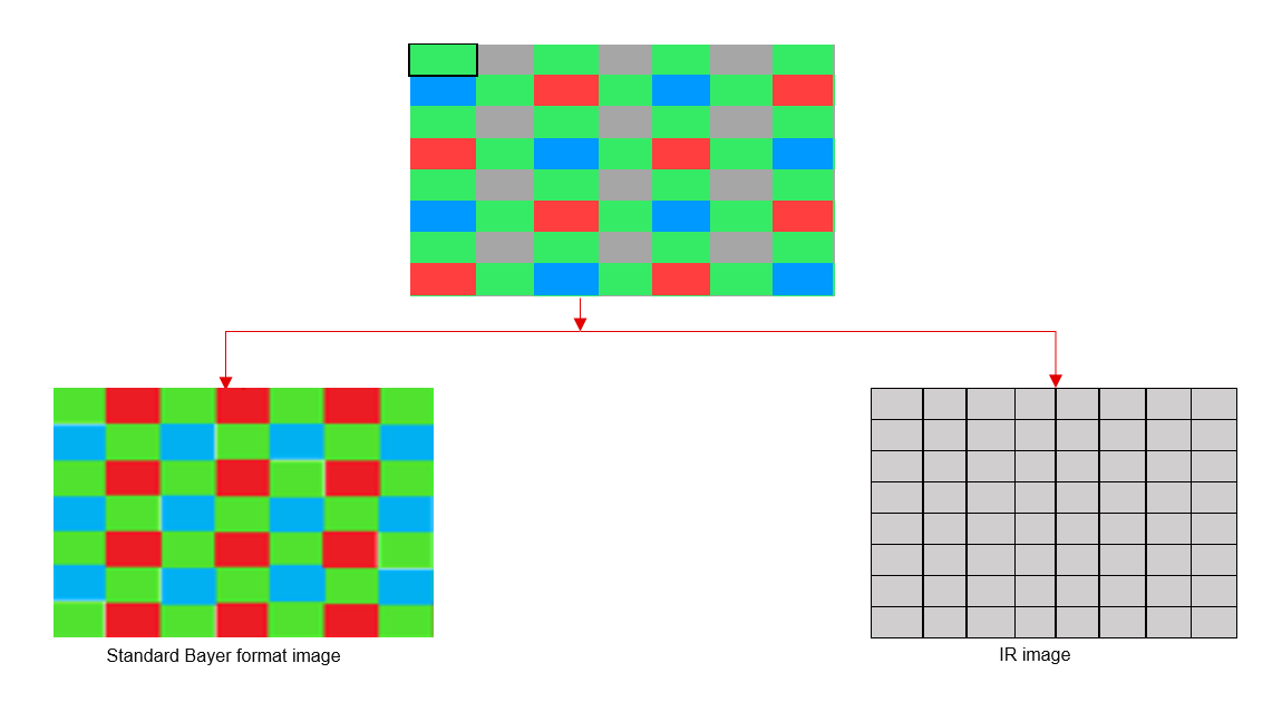
API Syntax
template <int FSIZE1 = 5, int FSIZE2 = 3, int BFORMAT = 0,
  int TYPE, int ROWS, int COLS, int NPPC = 1,
  int XFCV_DEPTH, int BORDER_T = XF_BORDER_CONSTANT,
  int USE_URAM = 0>
void rgbir2bayer(xf::cv::Mat<TYPE, ROWS, COLS, NPPC>& _src,
            char R_IR_C1_wgts[FSIZE1 * FSIZE1],
            char R_IR_C2_wgts[FSIZE1 * FSIZE1],
            char B_at_R_wgts[FSIZE1 * FSIZE1],
            char IR_at_R_wgts[FSIZE2 * FSIZE2],
            char IR_at_B_wgts[FSIZE2 * FSIZE2],
            char sub_wgts[4],
            xf::cv::Mat<TYPE, ROWS, COLS, NPPC>& _dst_rggb,
            xf::cv::Mat<TYPE, ROWS, COLS, NPPC>& _dst_ir)
Parameter Descriptions
The following table describes the template and the function parameters.
| Parameter | Description |
|---|---|
| FSIZE1 | Filter size for RGB pixels |
| FSIZE2 | Filter size for IR pixels |
| BFORMAT | Bayer format. Supported types are XF_BAYER_GR and XF_BAYER_BG |
| TYPE | Input pixel Type. 8-bit, 10 bit, 12 bit and 16 bit unsigned, 1 channel is supported (XF_8UC1,XF_10UC1, XF_12UC1, XF_16UC1). |
| ROWS | Maximum height of input and output image. |
| COLS | Maximum width of input and output image. Must be multiple of NPC. |
| NPPC | Number of pixels to be processed per cycle, possible options are XF_NPPC1 only. |
| XFCV_DEPTH | Depth of the hls::stream formed by the xf::Mat |
| BORDER_T | Border handling type. Fixed to XF_BORDER_CONSTANT |
| USE_URAM | Enable URAM storage strucure |
| _src_mat | Input image |
| R_IR_C1_wgts | Weights to calculate R at IR location for constellation 1 |
| R_IR_C2_wgts | Weights to calculate R at IR location for constellation 2 |
| B_at_R_wgts | Weights to calculate B at R location |
| IR_at_R_wgts | Weights to calculate IR at R location |
| IR_at_B_wgts | Weights to calculate IR at B location |
| sub_wgts | Weights to perform weighted subtraction of IR image from RGB image. sub_wgts[0] -> G Pixel, sub_wgts[1] -> R Pixel, sub_wgts[2] -> B Pixel sub_wgts[3] -> calculated B Pixel |
| _dst_rggb | output image in standard bayer format with only R,G,B pixels |
| _dst_ir | IR output image with only IR pixels |
Resource Utilization
The following table summarizes the resource utilization in different configurations, generated using Vitis HLS 2021.1 tool for the Xczu9eg-ffvb1156-1-i-es1 FPGA.
| Operating Mode | Operating Frequency (MHz) | Utilization Estimate | ||||
|---|---|---|---|---|---|---|
| BRAM_18K | DSP_48Es | FF | LUT | CLB | ||
| 1 Pixel | 300 | 37 | 0 | 4345 | 6243 | 1366 |
Performance Estimate
The following table summarizes the performance of the kernel in 1-pixel mode as generated using Vitis HLS 2021.1 tool for the Xilinx xczu9eg-ffvb1156-2-i-es2 FPGA to process a grayscale 4K (2160x3840) image.
| Operating Mode | Latency Estimate |
|---|---|
| Max Latency (ms) | |
| 1 pixel operation (300 MHz) | 27.7 |
BGR to HSV Conversion
The BGR2HSV function converts the input image color space to HSV
color space and returns the HSV image as the output.
API Syntax
template<int SRC_T, int ROWS, int COLS,int NPC=1>
          void BGR2HSV(xf::cv::Mat<SRC_T, ROWS, COLS, NPC> & _src_mat,xf::cv::Mat<SRC_T, ROWS, COLS, NPC> & _dst_mat)
Parameter Descriptions
The table below describes the template and the function parameters.
Parameter Description SRC_T Input pixel type should be XF_8UC3 DST_T Output pixel type should be XF_8UC3 ROWS Maximum height of input and output image COLS Maximum width of input and output image. Must be multiple of 8, for 8-pixel operation. NPC Number of pixels to be processed per cycle. Only XF_NPPC1 is supported. _src_mat Input image _dst_mat Output image
Scharr Filter
The Scharr function computes the gradients of input image in both x
and y direction by convolving the kernel with input image being
processed.
For Kernel size 3x3:
- GradientX:

- GradientY:

API Syntax
template<int BORDER_TYPE, int SRC_T,int DST_T, int ROWS, int COLS,int NPC=1>
void Scharr(xf::cv::Mat<SRC_T, ROWS, COLS, NPC> & _src_mat,xf::cv::Mat<DST_T, ROWS, COLS, NPC> & _dst_matx,xf::cv::Mat<DST_T, ROWS, COLS, NPC> & _dst_maty)
Parameter Descriptions
The following table describes the template and the function parameters.
| Parameter | Description |
|---|---|
| BORDER_TYPE | Border type supported is XF_BORDER_CONSTANT |
| SRC_T | Input pixel type. Only 8-bit, unsigned, 1 and 3 channels are supported (XF_8UC1 and XF_8UC3) |
| DST_T | Output pixel type. Only 8-bit unsigned, 16-bit signed,1 and 3 channels are supported (XF_8UC1, XF_16SC1,XF_8UC3 and XF_16SC3) |
| ROWS | Maximum height of input and output image |
| COLS | Maximum width of input and output image. Must be multiple of 8, for 8-pixel operation. |
| NPC | Number of pixels to be processed per cycle; possible options are XF_NPPC1 and XF_NPPC8 for 1 pixel and 8 pixel operations respectively. |
| _src_mat | Input image |
| _dst_matx | X gradient output image. |
| _dst_maty | Y gradient output image. |
Resource Utilization
The following table summarizes the resource utilization of the kernel in different configurations, generated using Vivado HLS 2019.1 tool for the Xilinx Xczu9eg-ffvb1156-1-i-es1 FPGA, to process a grayscale HD (1080x1920) image.
| Name | Resource Utilization | |
|---|---|---|
| 1 pixel per clock operation | 8 pixel per clock operation | |
| 300 MHz | 150 MHz | |
| BRAM_18K | 3 | 6 |
| DSP48E | 0 | 0 |
| FF | 728 | 1434 |
| LUT | 812 | 2481 |
| CLB | 171 | 461 |
The following table summarizes the resource utilization of the kernel in different configurations, generated using Vivado HLS 2019.1 tool for the Xilinx Xczu9eg-ffvb1156-1-i-es1 FPGA, to process a 4K 3 channel image.
| Name | Resource Utilization |
|---|---|
| 1 pixel per clock operation | |
| 300 MHz | |
| BRAM_18K | 18 |
| DSP48E | 0 |
| FF | 1911 |
| LUT | 1392 |
Performance Estimate
The following table summarizes the performance of the kernel in different configurations, as generated using Vivado HLS 2019.1 tool for the Xilinx Xczu9eg-ffvb1156-1-i-es1, to process a grayscale HD (1080x1920) image.
| Operating Mode | Operating Frequency (MHz) |
Latency (ms) |
|---|---|---|
| 1 pixel | 300 | 7.2 |
| 8 pixel | 150 | 1.7 |
Set
The Set function sets the each pixel in input image to a given scalar value and stores the result in dst.
API Syntax
template< int SRC_T , int ROWS, int COLS, int NPC=1>
void set(xf::cv::Mat<SRC_T, ROWS, COLS, NPC> & _src1, unsigned char _scl[XF_CHANNELS(SRC_T,NPC)], xf::cv::Mat<SRC_T, ROWS, COLS, NPC> & _dst)
Parameter Descriptions
The following table describes the template and the function parameters.
| Parameter | Description |
|---|---|
| SRC_T | Input pixel type. 8-bit, unsigned, 1 channel is supported (XF_8UC1). |
| ROWS | Maximum height of input and output image |
| COLS | Maximum width of input and output image. Must be multiple of 8, for 8-pixel operation. |
| NPC | Number of pixels to be processed per cycle. |
| _src1 | First input image |
| _scl | Scalar value |
| _dst | Output image |
Resource Utilization
The following table summarizes the resource utilization of the Set function in Resource optimized (8 pixel) mode and normal mode as generated using Vivado HLS 2019.1 version tool for the Xczu9eg-ffvb1156-1-i-es1 FPGA.
| Name | Resource Utilization | |
|---|---|---|
| 1 pixel per clock operation | 8 pixel per clock operation | |
| 300 MHz | 150 MHz | |
| BRAM_18K | 0 | 0 |
| DSP48E | 0 | 0 |
| FF | 87 | 87 |
| LUT | 43 | 42 |
| CLB | 17 | 18 |
Performance Estimate
The following table summarizes a performance estimate of the kernel in different configurations, generated using Vivado HLS 2019.1 tool for Xczu9eg-ffvb1156-1-i-es1 FPGA to process a grayscale HD (1080x1920) image.
| Operating Mode | Latency Estimate |
|---|---|
| Max Latency (ms) | |
| 1 pixel operation (300 MHz) | 6.9 |
| 8 pixel operation (150 MHz) | 1.7 |
Sobel Filter
The Sobel function Computes the gradients of input image in both x
and y direction by convolving the kernel with input image being
processed.
- For Kernel size 3x3
- GradientX:

- GradientY:

- GradientX:
- For Kernel size 5x5
- GradientX:

- GradientY:

- GradientX:
- For Kernel size 7x7
- GradientX:

- GradientY:

- GradientX:
API Syntax
template<int BORDER_TYPE,int FILTER_TYPE, int SRC_T,int DST_T, int ROWS, int COLS,int NPC=1,bool USE_URAM=false>
void Sobel(xf::cv::Mat<SRC_T, ROWS, COLS, NPC> & _src_mat,xf::cv::Mat<DST_T, ROWS, COLS, NPC> & _dst_matx,xf::cv::Mat<DST_T, ROWS, COLS, NPC> & _dst_maty)
Parameter Descriptions
The following table describes the template and the function parameters.
| Parameter | Description |
|---|---|
| FILTER_TYPE | Filter size. Filter size of 3 (XF_FILTER_3X3), 5 (XF_FILTER_5X5) and 7 (XF_FILTER_7X7) are supported. |
| BORDER_TYPE | Border Type supported is XF_BORDER_CONSTANT |
| SRC_T | Input pixel type. Only 8-bit, unsigned, 1 and 3 channels are supported (XF_8UC1 and XF_8UC3) |
| DST_T | Output pixel type. Only 8-bit unsigned, 16-bit signed,1 and 3 channels are supported (XF_8UC1, XF_16SC1,XF_8UC3 and XF_16SC3) |
| ROWS | Maximum height of input and output image. |
| COLS | Maximum width of input and output image. Must be multiple of 8, for 8-pixel operation. |
| NPC | Number of pixels to be processed per cycle; possible options are XF_NPPC1 and XF_NPPC8 for 1 pixel and 8 pixel operations respectively. |
| USE_URAM | Enable to map storage structures to UltraRAM |
| _src_mat | Input image |
| _dst_matx | X gradient output image. |
| _dst_maty | Y gradient output image. |
|
|
Resource Utilization
The following table summarizes the resource utilization of the kernel in different configurations, generated using Vivado HLS 2019.1 tool for the Xilinx Xczu9eg-ffvb1156-1-i-es1 FPGA, to process a grayscale HD (1080x1920) image.
| Operating Mode | Filter Size | Operating Frequency (MHz) |
Utilization Estimate | ||||
|---|---|---|---|---|---|---|---|
| BRAM_18K | DSP_48Es | FF | LUT | CLB | |||
| 1 pixel | 3x3 | 300 | 3 | 0 | 609 | 616 | 135 |
| 5x5 | 300 | 5 | 0 | 1133 | 1499 | 308 | |
| 7x7 | 300 | 7 | 0 | 2658 | 3334 | 632 | |
| 8 pixel | 3x3 | 150 | 6 | 0 | 1159 | 1892 | 341 |
| 5x5 | 150 | 10 | 0 | 3024 | 5801 | 999 | |
The following table summarizes the resource utilization of the kernel in different configurations, generated using Vivado HLS 2019.1 tool for the Xilinx Xczu9eg-ffvb1156-1-i-es1 FPGA, to process a 4K 3 Channel image.
| Operating Mode | Filter Size | Operating Frequency (MHz) |
Utilization Estimate | |||
|---|---|---|---|---|---|---|
| BRAM_18K | DSP_48Es | FF | LUT | |||
| 1 pixel | 3x3 | 300 | 18 | 0 | 1047 | 1107 |
| 5x5 | 300 | 30 | 0 | 5370 | 3312 | |
| 7x7 | 300 | 42 | 0 | 6100 | 5496 | |
The following table summarizes the resource utilization of the kernel in different configurations, generated using Vivado HLS 2019.1 tool for the Xilinx xczu7ev-ffvc1156-2-e FPGA, to process a grayscale 4K (3840x2160) image with UltraRAM enable.
| Operating Mode | Filter Size | Operating Frequency (MHz) |
Utilization Estimate | ||||
|---|---|---|---|---|---|---|---|
| BRAM_18K | URAM | DSP_48Es | FF | LUT | |||
| 1 pixel | 3x3 | 300 | 0 | 1 | 0 | 919 | 707 |
| 5x5 | 300 | 0 | 1 | 0 | 2440 | 1557 | |
| 7x7 | 300 | 0 | 1 | 0 | 4066 | 3495 | |
| 8 pixel | 3x3 | 150 | 0 | 3 | 0 | 1803 | 2050 |
| 5x5 | 150 | 0 | 5 | 0 | 4159 | 6817 | |
Performance Estimate
The following table summarizes the performance of the kernel in different configurations, as generated using Vivado HLS 2019.1 tool for the Xilinx Xczu9eg-ffvb1156-1-i-es1, to process a grayscale HD (1080x1920) image.
| Operating Mode | Operating Frequency (MHz) |
Filter Size | Latency Estimate (ms) |
|---|---|---|---|
| 1 pixel | 300 | 3x3 | 7.5 |
| 300 | 5x5 | 7.5 | |
| 300 | 7x7 | 7.5 | |
| 8 pixel | 150 | 3x3 | 1.7 |
| 150 | 5x5 | 1.71 |
Semi Global Method for Stereo Disparity Estimation
Stereo matching algorithms are used for finding relative depth from a pair of rectified stereo images. The resultant disparity information can be used for 3D reconstruction by triangulation, using the known intrinsic and extrinsic parameters of the stereo camera. The Semi global method for stereo disparity estimation aggregates the cost in terms of dissimilarity across multiple paths leading to a smoother estimate of the disparity map.
For the semi-global method in Vitis Vision, census transform in conjunction with Hamming distance is used for cost computation. The semiglobal optimization block is based on the implementation by Hirschmuller, but approximates the cost aggregation by considering only four directions.
Parallelism is achieved by computing and aggregating cost for multiple disparities in parallel, and this parameter is included as a compile-time input.
API Syntax
template<int BORDER_TYPE, int WINDOW_SIZE, int NDISP, int PU, int R, int SRC_T, int DST_T, int ROWS, int COLS, int NPC>
void SemiGlobalBM(xf::cv::Mat<SRC_T,ROWS,COLS,NPC> & _src_mat_l, xf::cv::Mat<SRC_T,ROWS,COLS,NPC> & _src_mat_r, xf::cv::Mat<DST_T,ROWS,COLS,NPC> & _dst_mat, uint8_t p1, uint8_t p2)
Parameter Descriptions
The following table describes the template and the function parameters.
| Parameter | Description |
|---|---|
| BORDER_TYPE | The border pixels are processed in Census transform function based on this parameter. Only XF_BORDER_CONSTANT is supported. |
| WINDOW_SIZE | Size of the window used for Census transform computation. Only ‘5’ (5x5) is supported. |
| NDISP | Number of disparities |
| PU | Number of disparity units to be computed in parallel |
| R | Number of directions for cost aggregation. It must be 2, 3, or 4. |
| SRC_T | Type of input image Mat object. It must be XF_8UC1. |
| DST_T | Type of output disparity image Mat object. It must be XF_8UC1. |
| ROWS | Maximum height of the input image. |
| COLS | Maximum width of the input image. |
| NPC | Number of pixels to be computed in parallel. It must be XF_NPPC1. |
| _src_mat_l | Left input image Mat |
| _src_mat_r | Right input image Mat |
| _dst_mat | Output disparity image Mat |
| p1 | Small penalty for cost aggregation |
| p2 | Large penalty for cost aggregation. The maximum value is 100. |
Resource Utilization
The following table summarizes the resource utilization for a 1920 x 1080 image, with 64 number of disparities, and 32 parallel units.
| Operating Mode | Filter Size | Operating Frequency (MHz) | Utilization Estimate | |||
|---|---|---|---|---|---|---|
| BRAM_18K | DSP_48Es | FF | LUT | |||
| 1 Pixel | 5x5 | 200 | 205 | 141 | 11856 | 19102 |
Performance Estimate
The following table summarizes a performance estimate for a 1920x1080 image.
| Operating Mode | Operating Frequency | Number of Disparities | Parallel Units | Latency |
|---|---|---|---|---|
| 1 pixel/clock | 200 MHz | 64 | 32 | 42 ms |
Stereo Local Block Matching
Stereo block matching is a method to estimate the motion of the blocks between the consecutive frames, called stereo pair. The postulate behind this idea is that, considering a stereo pair, the foreground objects will have disparities higher than the background. Local block matching uses the information in the neighboring patch based on the window size, for identifying the conjugate point in its stereo pair. While, the techniques under global method, used the information from the whole image for computing the matching pixel, providing much better accuracy than local methods. But, the efficiency in the global methods are obtained with the cost of resources, which is where local methods stands out.
Local block matching algorithm consists of pre-processing and disparity estimation stages. The pre-processing consists of Sobel gradient computation followed by image clipping. And the disparity estimation consists of SAD (Sum of Absolute Difference) computation and obtaining the disparity using winner takes all method (least SAD will be the disparity). Invalidity of the pixel relies upon its uniqueness from the other possible disparities. And the invalid pixels are indicated with the disparity value of zero.
API Syntax
template <int WSIZE, int NDISP, int NDISP_UNIT, int SRC_T, int DST_T, int ROWS, int COLS, int NPC = XF_NPPC1,bool USE_URAM=false>
void StereoBM(xf::cv::Mat<SRC_T, ROWS, COLS, NPC> &_left_mat, xf::cv::Mat<SRC_T, ROWS, COLS, NPC> &_right_mat, xf::cv::Mat<DST_T, ROWS, COLS, NPC> &_disp_mat, xf::cv::xFSBMState<WSIZE,NDISP,NDISP_UNIT> &sbmstate);
Parameter Descriptions
The following table describes the template and the function parameters.
| Parameter | Description |
|---|---|
| WSIZE | Size of the window used for disparity computation |
| NDISP | Number of disparities |
| NDISP_UNITS | Number of disparities to be computed in parallel. |
| SRC_T | Input pixel type. Only 8-bit, unsigned, 1 channel is supported (XF_8UC1) |
| DST_T | Output type. This is XF_16UC1, where the disparities are arranged in Q12.4 format. |
| ROWS | Maximum height of input and output image |
| COLS | Maximum width of input and output image |
| NPC | Number of pixels to be processed per cycle; possible options are XF_NPPC1 only. |
| USE_URAM | Enable to map some storage structures to UltraRAM |
| left_image | Image from the left camera |
| right_image | Image from the right camera |
| disparity_im age | Disparities output in the form of an image. |
| sbmstate | Class object consisting of various parameters regarding the stereo block matching algorithm.
|
Resource Utilization
The following table summarizes the resource utilization of the kernel in different configurations, generated using Vivado HLS 2019.1 version tool for the Xilinx® Xczu9eg-ffvb1156-1-i-es1 FPGA, to progress a grayscale HD (1080x1920) image.
The configurations are in the format: imageSize_WSIZE_NDisp_NDispUnits.
| Configurations | Frequency (MHz) |
Resource Utilization | |||
|---|---|---|---|---|---|
| BRAM_18k | DSP48E | FF | LUT | ||
| HD_5_16_2 | 300 | 37 | 20 | 6856 | 7181 |
| HD_9_32_4 | 300 | 45 | 20 | 9700 | 10396 |
| HD_11_32_32 | 300 | 49 | 20 | 34519 | 31978 |
| HD_15_128_32 | 300 | 57 | 20 | 41017 | 35176 |
| HD_21_64_16 | 300 | 69 | 20 | 29853 | 30706 |
The following table summarizes the resource utilization of the kernel in different configurations, generated using Vivado HLS 2019.1 version tool for the Xilinx xczu7ev-ffvc1156-2-e FPGA, to progress a grayscale HD (1080x1920) image with UltraRAM enable.
The configurations are in the format: imageSize_WSIZE_NDisp_NDispUnits.
| Configurations | Frequency (MHz) |
Resource Utilization | ||||
|---|---|---|---|---|---|---|
| BRAM_18k | URAM | DSP48E | FF | LUT | ||
| HD_5_16_2 | 300 | 0 | 12 | 20 | 7220 | 6529 |
| HD_9_32_4 | 300 | 0 | 12 | 20 | 10186 | 9302 |
| HD_11_32_32 | 300 | 0 | 14 | 20 | 44046 | 30966 |
| HD_15_128_32 | 300 | 0 | 14 | 20 | 50556 | 38132 |
| HD_21_64_16 | 300 | 0 | 16 | 20 | 35991 | 28464 |
Performance Estimate
The following table summarizes a performance estimate of the Stereo local block matching in different configurations, as generated using Vivado HLS 2019.1 tool for Xilinx Xczu9eg-ffvb1156-1-i-es1 FPGA, to process a grayscale HD (1080x1920) image.
The configurations are in the format: imageSize_WSIZE_NDisp_NDispUnits.
| Configurations | Frequency (MHz) |
Latency (ms) | |
|---|---|---|---|
| Min | Max | ||
| HD_5_16_2 | 300 | 55.296 | 55.296 |
| HD_9_32_4 | 300 | 55.296 | 55.296 |
| HD_11_32_32 | 300 | 6.912 | 6.912 |
| HD_15_48_16 | 300 | 20.736 | 20.736 |
| HD_15_128_32 | 300 | 27.648 | 27.648 |
| HD_21_64_16 | 300 | 27.648 | 27.648 |
SubRS
The SubRS function subtracts the intensity of the source image from a scalar image and stores it in the destination image.
dst(I)= scl - src(I)
API Syntax
template<int POLICY_TYPE, int SRC_T, int ROWS, int COLS, int NPC =1>
void subRS(xf::cv::Mat<SRC_T, ROWS, COLS, NPC> & _src1, unsigned char _scl[XF_CHANNELS(SRC_T,NPC)],xf::cv::Mat<SRC_T, ROWS, COLS, NPC> & _dst)
Parameter Descriptions
The following table describes the template and the function parameters.
| Parameter | Description |
|---|---|
| SRC_T | Input Pixel Type. 8-bit, unsigned, 1 channel is supported (XF_8UC1). |
| ROWS | Maximum height of input and output image |
| COLS | Maximum width of input and output image. In case of N-pixel parallelism, width should be multiple of N. |
| NPC | Number of pixels to be processed per cycle; possible options are XF_NPPC1 and XF_NPPC8 for 1 pixel and 8 pixel operations respectively. |
| _src1 | First Input image |
| _scl | Input scalar value,the size should be number of channels |
| _dst | Output image |
Resource Utilization
The following table summarizes the resource utilization of the SubRS function in Resource optimized (8 pixel) mode and normal mode as generated using Vivado HLS 2019.1 version tool for the Xczu9eg-ffvb1156-1-i-es1 FPGA.
| Name | Resource Utilization | |
|---|---|---|
| 1 pixel per clock operation | 8 pixel per clock operation | |
| 300 MHz | 150 MHz | |
| BRAM_18K | 0 | 0 |
| DSP48E | 0 | 0 |
| FF | 103 | 104 |
| LUT | 44 | 133 |
| CLB | 23 | 43 |
Performance Estimate
The following table summarizes a performance estimate of the kernel in different configurations, generated using Vivado HLS 2019.1 tool for Xczu9eg-ffvb1156-1-i-es1 FPGA to process a grayscale HD (1080x1920) image.
| Operating Mode | Latency Estimate |
|---|---|
| Max Latency (ms) | |
| 1 pixel operation (300 MHz) | 6.9 |
| 8 pixel operation (150 MHz) | 1.7 |
SubS
The SubS function subtracts a scalar value from the intensity of source image and stores it in the destination image.
dst(I)= src(I) - scl
API Syntax
template<int POLICY_TYPE, int SRC_T, int ROWS, int COLS, int NPC =1>
void subS(xf::cv::Mat<SRC_T, ROWS, COLS, NPC> & _src1, unsigned char _scl[XF_CHANNELS(SRC_T,NPC)],xf::cv::Mat<SRC_T, ROWS, COLS, NPC> & _dst)
Parameter Descriptions
The following table describes the template and the function parameters.
| Parameter | Description |
|---|---|
| SRC_T | Input Pixel Type. 8-bit, unsigned, 1 channel is supported (XF_8UC1). |
| ROWS | Maximum height of input and output image. |
| COLS | Maximum width of input and output image. In case of N-pixel parallelism, width should be multiple of N. |
| NPC | Number of pixels to be processed per cycle; possible options are XF_NPPC1 and XF_NPPC8 for 1 pixel and 8 pixel operations respectively. |
| _src1 | First Input image |
| _scl | Input scalar value, the size should be the number of channels. |
| _dst | Output image |
Resource Utilization
The following table summarizes the resource utilization of the SubS function in Resource optimized (8 pixel) mode and normal mode as generated using Vivado HLS 2019.1 version tool for the Xczu9eg-ffvb1156-1-i-es1 FPGA.
| Name | Resource Utilization | |
|---|---|---|
| 1 pixel per clock operation | 8 pixel per clock operation | |
| 300 MHz | 150 MHz | |
| BRAM_18K | 0 | 0 |
| DSP48E | 0 | 0 |
| FF | 103 | 104 |
| LUT | 44 | 133 |
| CLB | 23 | 43 |
Performance Estimate
The following table summarizes a performance estimate of the kernel in different configurations, generated using Vivado HLS 2019.1 tool for Xczu9eg-ffvb1156-1-i-es1 FPGA to process a grayscale HD (1080x1920) image.
| Operating Mode | Latency Estimate |
|---|---|
| Max Latency (ms) | |
| 1 pixel operation (300 MHz) | 6.9 |
| 8 pixel operation (150 MHz) | 1.7 |
Sum
The sum function calculates the sum of all pixels in input image.
API Syntax
template< int SRC_T , int ROWS, int COLS, int NPC=1>
void sum(xf::cv::Mat<SRC_T, ROWS, COLS, NPC> & src1,double sum[XF_CHANNELS(SRC_T,NPC)])
Parameter Descriptions
The following table describes the template and the function parameters.
| Parameter | Description |
|---|---|
| SRC_T | Input pixel type. 8-bit, unsigned, 1 channel is supported (XF_8UC1). |
| ROWS | Maximum height of input and output image. |
| COLS | Maximum width of input and output image (must be multiple of 8). |
| NPC | Number of pixels to be processed per cycle. |
| _src1 | Input image. |
| sum | Array to store sum of all pixels in the image. |
Resource Utilization
The following table summarizes the resource utilization of the Sum function in Resource optimized (8 pixel) mode and normal mode as generated using Vivado HLS 2019.1 version tool for the Xczu9eg-ffvb1156-1-i-es1 FPGA.
| Name | Resource Utilization | |
|---|---|---|
| 1 pixel per clock operation | 8 pixel per clock operation | |
| 300 MHz | 150 MHz | |
| BRAM_18K | 0 | 0 |
| DSP48E | 0 | 0 |
| FF | 341 | 408 |
| LUT | 304 | 338 |
| CLB | 71 | 87 |
Performance Estimate
The following table summarizes a performance estimate of the kernel in different configurations, generated using Vivado HLS 2019.1 tool for Xczu9eg-ffvb1156-1-i-es1 FPGA to process a grayscale HD (1080x1920) image.
| Operating Mode | Latency Estimate |
|---|---|
| Max Latency (ms) | |
| 1 pixel operation (300 MHz) | |
| 8 pixel operation (150 MHz) |
SVM
The SVM function is the SVM core operation, which performs dot
product between the input arrays. The function returns the resultant dot
product value with its fixed point type.
API Syntax
template<int SRC1_T, int SRC2_T, int DST_T, int ROWS1, int COLS1, int ROWS2, int COLS2, int NPC=1, int N>
void SVM(xf::cv::Mat<SRC1_T, ROWS1, COLS1, NPC> &in_1, xf::cv::Mat<SRC2_T, ROWS2, COLS2, NPC> &in_2, uint16_t idx1, uint16_t idx2, uchar_t frac1, uchar_t frac2, uint16_t n, uchar_t *out_frac, ap_int<XF_PIXELDEPTH(DST_T)> *result)
Parameter Descriptions
The following table describes the template and the function parameters.
| Parameters | Description |
|---|---|
| SRC1_T | Input pixel type. 16-bit, signed, 1 channel (XF_16SC1) is supported. |
| SRC2_T | Input pixel type. 16-bit, signed, 1 channel (XF_16SC1) is supported. |
| DST_T | Output data Type. 32-bit, signed, 1 channel (XF_32SC1) is supported. |
| ROWS1 | Number of rows in the first image being processed. |
| COLS1 | Number of columns in the first image being processed. |
| ROWS2 | Number of rows in the second image being processed. |
| COLS2 | Number of columns in the second image being processed. |
| NPC | Number of pixels to be processed per cycle; possible options are XF_NPPC1. |
| N | Max number of kernel operations |
| in_1 | First Input Array. |
| in_2 | Second Input Array. |
| idx1 | Starting index of the first array. |
| idx2 | Starting index of the second array. |
| frac1 | Number of fractional bits in the first array data. |
| frac2 | Number of fractional bits in the second array data. |
| n | Number of kernel operations. |
| out_frac | Number of fractional bits in the resultant value. |
| result | Resultant value |
Resource Utilization
The following table summarizes the resource utilization of the SVM function, generated using Vivado HLS 2019.1 tool for the Xilinx Xczu9eg-ffvb1156-1-i-es1 FPGA.
| Operating Frequency (MHz) | Utilization Estimate (ms) | ||||
|---|---|---|---|---|---|
| BRAM_18K | DSP_48Es | FF | LUT | CLB | |
| 300 | 0 | 1 | 27 | 34 | 12 |
Performance Estimate
The following table summarizes the performance in different configurations, as generated using Vivado HLS 2019.1 tool for the Xilinx Xczu9eg-ffvb1156-1-i-es1 FPGA.
| Operating Frequency (MHz) | Latency Estimate | |
|---|---|---|
| Min (cycles) | Max (cycles) | |
| 300 | 204 | 204 |
3D LUT
3D Look Up Tables (LUTs) may look similar to 1D LUTs in their principle of using value as mapping indexes to get the new value, they differ in the sense that they operate on three independent parameters. This drastically increases the number of mapped indexes to value pairs. For example, a combination of 3 individual 1D LUTs can map 2^n * 3 values where n is the bitdepth, whereas a 3D LUT processing 3 channels will have 2^n * 2^n * 2^n possible values.
Since all those huge number of values cannot be stored, only a subset of them are saved and the remaining values are computed through interpolation. The current implementation supports trilinear interpolation.
API Syntax
template <int LUTDIM, int SQLUTDIM, int INTYPE, int OUTTYPE, int ROWS, int COLS, int NPPC = 1, int URAM = 0>
void lut3d(xf::cv::Mat<INTYPE, ROWS, COLS, NPPC>& in_img,
           xf::cv::Mat<XF_32FC3, SQLUTDIM, LUTDIM, NPPC>& lut,
           xf::cv::Mat<OUTTYPE, ROWS, COLS, NPPC>& out_img,
           unsigned char lutdim)
The following table describes the template and the function parameters.
| Parameter | Description |
|---|---|
| LUTDIM | Maximum dimension of input LUT |
| SQLUTDIM | Squared value of maximum dimension of input LUT |
| INTYPE | Input Pixel Type. XF_8UC3, XF_10UC3, XF_12UC3, XF_16UC3 supported |
| OUTTYPE | Output Pixel Type. XF_8UC3, XF_10UC3, XF_12UC3, XF_16UC3 supported |
| ROWS | Maximum height of input and output image |
| COLS | Maximum width of input and output image |
| NPPC | Number of Pixels to be processed per cycle. Only XF_NPPC1 supported |
| URAM | Enable to map storage structures to UltraRAM. |
| in_img | Input image |
| lut | Input lut |
| out_img | Output image |
| lutdim | Dimension of input lut |
Resource Utilization
The following table summarizes the resource utilization of the kernel in different configurations, generated using Vitis HLS 2020.2 tool for the Xilinx Alveo U200 FPGA, to process a 4K image.
| Operating Mode | Operating Frequency (MHz) |
Utilization Estimate | ||||
|---|---|---|---|---|---|---|
| BRAM_18K | DSP_48Es | FF | LUT | SLICE | ||
| 1 pixel | 300 | 30 | 40 | 9182 | 12039| 847 | |||
Performance Estimate
The following table summarizes a performance estimate of the kernel in different configurations, as generated using Vitis HLS 2020.2 tool for the Xilinx Alveo U200 FPGA, to process 4K image.
| Operating Mode | Operating Frequency (MHz) |
Latency Estimate |
|---|---|---|
| Max (ms) | ||
| 1 pixel | 300 | 28.5 |
Thresholding
The Threshold function performs thresholding operation on the input
image. There are several types of thresholding supported by the
function.


API Syntax
template<int THRESHOLD_TYPE, int SRC_T, int ROWS, int COLS,int NPC=1>
void Threshold(xf::cv::Mat<SRC_T, ROWS, COLS, NPC> & _src_mat,xf::cv::Mat<SRC_T, ROWS, COLS, NPC> & _dst_mat,short int thresh,short int maxval )
Parameter Descriptions
The following table describes the template and the function parameters.
| Parameter | Description |
|---|---|
| THRESHOLD_TY PE | Type of thresholding. |
| SRC_T | Input pixel type. Only 8-bit, unsigned, 1 channel is supported (XF_8UC1). |
| ROWS | Maximum height of input and output image. |
| COLS | Maximum width of input and output image. Must be multiple of 8, for 8-pixel operation. |
| NPC | Number of pixels to be processed per cycle. |
| _src_mat | Input image |
| _dst_mat | Output image |
| thresh | Threshold value. |
| maxval | Maximum value to use with the THRESH_BINARY and
THRESH_BINARY_INV thresholding types. |
Resource Utilization
The following table summarizes the resource utilization of the kernel with binary thresholding in different configurations, generated using Vivado HLS 2019.1 tool for the Xilinx Xczu9eg-ffvb1156-1 FPGA, to process a grayscale HD (1080x1920) image.
| Name | Resource Utilization | |
|---|---|---|
| 1 pixel per clock operation | 8 pixel per clock operation | |
| 300 MHz | 150 MHz | |
| BRAM_18K | 0 | 0 |
| DSP48E | 0 | 0 |
| FF | 110 | 154 |
| LUT | 61 | 139 |
| CLB | 16 | 37 |
Performance Estimate
The following table summarizes the performance of the kernel in different configurations, as generated using Vivado HLS 2019.1 tool for the Xilinx Xczu9eg-ffvb1156-1, to process a grayscale HD (1080x1920) image.
| Operating Mode | Operating Frequency (MHz) |
Latency Estimate (ms) |
|---|---|---|
| 1 pixel | 300 | 7.2 |
| 8 pixel | 150 | 1.7 |
Atan2
The Atan2LookupFP function finds the arctangent of y/x. It returns
the angle made by the vector  with respect to origin. The
angle returned by atan2 will also contain the quadrant information.
with respect to origin. The
angle returned by atan2 will also contain the quadrant information.
Atan2LookupFP is a fixed point version of the standard atan2
function. This function implements the atan2 using a lookup table
approach. The values in the look up table are represented in Q4.12
format and so the values returned by this function are in Q4.12. A
maximum error of 0.2 degrees is present in the range of 89 to 90 degrees
when compared to the standard atan2 function available in glibc. For the
other angles (0 to 89) the maximum error is in the order of 10-3. This
function returns 0 when both xs and ys are zeroes.
API Syntax
short Atan2LookupFP(short xs, short ys, int M1,int N1,int M2, int N2)
Parameter Descriptions
The following table describes the template and the function parameters.
| Parameter | Description |
|---|---|
| xs | 16-bit signed value x in fixed point format of QM1.N1 |
| ys | 16-bit signed value y in fixed point format of QM2.N2 |
| M1 | Number of bits to represent integer part of x. |
| N1 | Number of bits to represent fractional part of y. Must be equal to 16-M1. |
| M2 | Number of bits to represent integer part of y. |
| N2 | Number of bits to represent fractional part of y. Must be equal to 16-N1. |
| Return | Return value is in radians. Its range varies from -pi to +pi in fixed point format of Q4.12 |
..rubric:: Resource Utilization
The following table summarizes the resource utilization of the
Atan2LookupFP function , generated using Vivado HLS 2019.1 tool for
the Xilinx Xczu9eg-ffvb1156-1-i-es1 FPGA.
Operating Frequency (MHz) |
Utilization Estimate | ||||
|---|---|---|---|---|---|
| BRAM_18K | DSP_48Es | FF | LUT | CLB | |
| 300 | 4 | 2 | 275 | 75 | 139 |
Performance Estimate
The following table summarizes the performance in different configurations, as generated using Vivado HLS 2019.1 tool for the Xilinx Xczu9eg-ffvb1156-1-i-es1 FPGA.
Operating Frequency (MHz) |
Latency Estimate | |
|---|---|---|
| Min (cycles) | Max (cycles) | |
| 300 | 1 | 15 |
Inverse (Reciprocal)
The Inverse function computes the reciprocal of a number x. The
values of 1/x are stored in a look up table of 2048 size. The index for
picking the 1/x value is computed using the fixed point format of x.
Once this index is computed, the corresponding 1/x value is fetched from
the look up table and returned along with the number of fractional bits
needed to represent this value in fixed point format.
API Syntax
unsigned int Inverse(unsigned short x,int M,char *N)
Parameter Descriptions
The following table describes the template and the function parameters.
| Parameter | Description |
|---|---|
| x | 16-bit unsigned value x in fixed point format of QM.(16-M) |
| M | Number of bits to represent integer part of x. |
| N | Pointer to a char variable which stores the number of bits to represent fractional part of 1/x. This value is returned from the function. |
| Return | 1/x value is returned in 32-bit format represented by a fixed point format of Q(32-N).N |
Resource Utilization
The following table summarizes the resource utilization of the Inverse function, generated using Vivado HLS 2019.1 tool for the Xilinx Xczu9eg-ffvb1156-1-i-es1 FPGA.
Operating Frequency (MHz) |
Utilization Estimate | ||||
|---|---|---|---|---|---|
| BRAM_18K | DSP_48Es | FF | LUT | CLB | |
| 300 | 4 | 0 | 68 | 128 | 22 |
Performance Estimate
The following table summarizes the performance in different configurations, as generated using Vivado HLS 2019.1 tool for the Xilinx Xczu9eg-ffvb1156-1-i-es1 FPGA.
Operating Frequency (MHz) |
Latency Estimate | |
|---|---|---|
| Min (cycles) | Max (cycles) | |
| 300 | 1 | 15 |
Square Root
The Sqrt function computes the square root of a 16-bit fixed point
number using the non-restoring square root algorithm. The non-restoring
square root algorithm uses the two’s complement representation for the
square root result. At each iteration the algorithm can generate exact
result value even in the last bit.
Input argument D must be 16-bit number, though it is declared as 32-bit. The output sqrt(D) is 16-bit type. If format of D is QM.N (where M+N = 16) then format of output is Q(M/2).N
To get a precision of ‘n’ bits in fractional part, you can simply left shift the radicand (D) by ‘2n’ before the function call and shift the solution right by ‘n’ to get the correct answer. For example, to find the square root of 35 (01100011:sub:2) with one bit after the decimal point, that is, N=1:
- Shift the number (0110001100:sub:2) left by 2
- Shift the answer (1011:sub:2) right by 1. The correct answer is 101.1, which is 5.5.
API Syntax
int Sqrt(unsigned int D)
Parameter Descriptions
The following table describes the template and the function parameters.
| Parameter | Description |
|---|---|
| D | Input data in a 16-bit fixed-point format. |
| Return | Output value in short int format. |
Resource Utilization
The following table summarizes the resource utilization of the Sqrt function, generated using Vivado HLS 2019.1 tool for the Xilinx Xczu9eg-ffvb1156-1-i-es1 FPGA.
Operating Frequency (MHz) |
Utilization Estimate | ||||
|---|---|---|---|---|---|
| BRAM_18K | DSP_48Es | FF | LUT | CLB | |
| 300 | 0 | 0 | 8 | 6 | 1 |
Performance Estimate
The following table summarizes the performance in different configurations, as generated using Vivado HLS 2019.1 tool for the Xilinx Xczu9eg-ffvb1156-1-i-es1 FPGA.
Operating Frequency (MHz) |
Latency Estimate | |
|---|---|---|
| Min (cycles) | Max (cycles) | |
| 300 | 18 | 18 |
Warp Transform
The warpTransform function is designed to perform the perspective
and affine geometric transformations on an image. The type of transform
is a compile time parameter to the function.
The function uses a streaming interface to perform the transformation. Due to this and due to the fact that geometric transformations need access to many different rows of input data to compute one output row, the function stores some rows of the input data in block RAMs/UltraRAMs. The number of rows the function stores can be configured by the user by modifying a template parameter. Based on the transformation matrix, you can decide on the number of rows to be stored. You can also choose when to start transforming the input image in terms of the number of rows of stored image.
Affine Transformation
The transformation matrix consists of size parameters, and is as shown:

Affine transformation is applied in the warpTransform function following the equation:

Perspective Transformation
The transformation matrix is a 3x3 matrix as shown below:

Perspective transformation is applied in warpTransform following the equation:

The destination pixel is then computed by dividing the first two dimensions of the dst1 by the third dimension

API Syntax
template<int STORE_LINES, int START_ROW, int TRANSFORMATION_TYPE, int INTERPOLATION_TYPE, int SRC_T, int ROWS, int COLS, int NPC=1,bool USE_URAM=false>
void warpTransform(xf::cv::Mat<SRC_T, ROWS, COLS, NPC> & src, xf::cv::Mat<SRC_T, ROWS, COLS, NPC> & dst, float *transformation_matrix)
Parameter Descriptions
The following table describes the template and the function parameters.
| Parameter | Description |
|---|---|
| STORE_LINES | Number of lines to store an input to process a given transformation. |
| START_ROW | Number of the input rows to store before starting the image transformation. This must be less than or equal to STORE_LINES. |
| TRANSFORMATI ON_TYPE | Affine and perspective transformations are supported. Set this flag to ‘0’ for affine and ‘1’ for perspective transformation. |
| INTERPOLATIO N_TYPE | Set flag to ‘1’ for bilinear interpolation and ‘0’ for nearest neighbor interpolation. |
| SRC_T | Input and Output pixel type. Only 8-bit, unsigned, 1 and 3 channels are supported (XF_8UC1 and XF_8UC3) |
| ROWS | Maximum height of input and output image. |
| COLS | Maximum width of input and output image. |
| NPC | Number of pixels to be processed per cycle; only one-pixel operation supported (XF_NPPC1). |
| USE_URAM | Enable to map some storage structures to UltraRAM |
| src | Input image |
| dst | Output image |
| transformati on_matrix | Transformation matrix that is applied to the input image. |
Resource Utilization
The following table summarizes the resource utilization of the Warp transform, generated using Vivado HLS 2019.1 version tool for the Xilinx Xczu9eg-ffvb1156-1-i-es1 FPGA, to process a grayscale HD (1080x1920) image.
| Transformation | INTERPOLATION _TYPE | STORE _LINES | START _ROW | Operating Frequency (MHz) |
Utilization Estimate | |||
|---|---|---|---|---|---|---|---|---|
| LUTs | FFs | DSPs | BRAMs | |||||
| Perspective | Bilinear | 100 | 50 | 300 | 7468 | 9804 | 61 | 112 |
| Perspective | Nearest Neighbor | 100 | 50 | 300 | 4514 | 6761 | 35 | 104 |
| Affine | Bilinear | 100 | 50 | 300 | 6139 | 5606 | 40 | 124 |
| Affine | Nearest Neighbor | 100 | 50 | 300 | 4611 | 4589 | 18 | 112 |
The following table summarizes the resource utilization of the Warp transform, generated using Vivado HLS 2019.1 version tool for the Xilinx Xczu9eg-ffvb1156-1-i-es1 FPGA, to process a BGR 4K image.
| Transformation | INTERPOLATION _TYPE | STORE _LINES | START _ROW | Operating Frequency (MHz) |
Utilization Estimate | |||
|---|---|---|---|---|---|---|---|---|
| LUTs | FFs | DSPs | BRAMs | |||||
| Perspective | Bilinear | 100 | 50 | 300 | 9192 | 7910 | 48 | 616 |
| Perspective | Nearest Neighbor | 100 | 50 | 300 | 10533 | 12055 | 69 | 604 |
| Affine | Bilinear | 100 | 50 | 300 | 6397 | 8415 | 35 | 604 |
The following table summarizes the resource utilization of the Warp transform, generated using Vivado HLS 2019.1 version tool for the Xilinx xczu7ev-ffvc1156-2-e FPGA, to progress a grayscale 4K image with UltraRAM enabled.
| Transformation | INTERPOLATION _TYPE | STORE _LINES | START _ROW | Operating Frequency (MHz) |
Utilization Estimate | ||||
|---|---|---|---|---|---|---|---|---|---|
| LUTs | FFs | DSPs | BRAMs | URAM | |||||
| Perspective | Bilinear | 100 | 50 | 300 | 7820 | 12458 | 61 | 7 | 12 |
| Perspective | Nearest Neighbor | 100 | 50 | 300 | 4880 | 8323 | 35 | 2 | 6 |
| Affine | Bilinear | 100 | 50 | 300 | 6850 | 9516 | 40 | 13 | 12 |
| Affine | Nearest Neighbor | 100 | 50 | 300 | 4651 | 6548 | 18 | 6 | 6 |
Performance Estimate
The following table summarizes a performance estimate of the Warp transform, as generated using Vivado HLS 2019.1 tool for Xilinx Xczu9eg-ffvb1156-1-i-es1 FPGA, to process a grayscale HD (1080x1920) image.
| Transforma tion | INTERPOLATI ON _TYPE | STORE _LIN ES | START _ROW | Operatin g Frequenc y (MHz) |
Latency Estimate Max (ms) |
|---|---|---|---|---|---|
| Perspectiv e | Bilinear | 100 | 50 | 300 | 7.46 |
| Perspectiv e | Nearest Neighbor | 100 | 50 | 300 | 7.31 |
| Affine | Bilinear | 100 | 50 | 300 | 7.31 |
| Affine | Nearest Neighbor | 100 | 50 | 300 | 7.24 |
Zero
The Zero function sets the each pixel in input image to zero and stores the result in dst.
API Syntax
template< int SRC_T , int ROWS, int COLS, int NPC=1>
void zero(xf::cv::Mat<SRC_T, ROWS, COLS, NPC> & _src1,xf::cv::Mat<SRC_T, ROWS, COLS, NPC> & _dst)
Parameter Descriptions
The following table describes the template and the function parameters.
| Parameter | Description |
|---|---|
| SRC_T | Input Pixel Type. 8-bit, unsigned, 1 channel is supported (XF_8UC1). |
| ROWS | Maximum height of input and output image. |
| COLS | Maximum width of input and output image. In case of N-pixel parallelism, width should be multiple of N. |
| NPC | Number of pixels to be processed per cycle; possible options are XF_NPPC1 and XF_NPPC8 for 1 pixel and 8 pixel operations respectively. |
| _src1 | Input image |
| _dst | Output image |
Resource Utilization
The following table summarizes the resource utilization of the Zero function in Resource optimized (8 pixel) mode and normal mode as generated using Vivado HLS 2019.1 version tool for the Xczu9eg-ffvb1156-1-i-es1 FPGA.
| Name | Resource Utilization | |
|---|---|---|
| 1 pixel per clock operation | 8 pixel per clock operation | |
| 300 MHz | 150 MHz | |
| BRAM_18K | 0 | 0 |
| DSP48E | 0 | 0 |
| FF | 78 | 78 |
| LUT | 42 | 41 |
| CLB | 15 | 14 |
Performance Estimate
The following table summarizes a performance estimate of the kernel in different configurations, generated using Vivado HLS 2019.1 tool for Xczu9eg-ffvb1156-1-i-es1 FPGA to process a grayscale HD (1080x1920) image.
| Operating Mode | Latency Estimate |
|---|---|
| Max Latency (ms) | |
| 1 pixel operation (300 MHz) | 6.9 |
| 8 pixel operation (150 MHz) | 1.7 |
1 N. Dalal, B. Triggs: Histograms of oriented gradients for human detection, IEEE Computer Society Conference on Computer Vision and Pattern Recognition, 2005.