5.1. Software Architecture of the Platform
5.1.1. Introduction
This chapter describes the application processing unit (APU) Linux software stack. The stack and vertical domains are shown in the following figure.
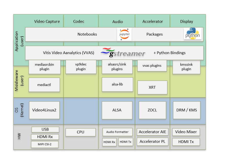
Linux Software Stack and Vertical Domains
The stack is horizontally divided into the following layers:
- Application layer (user-space)
- Jupyter notebooks with a simple control and visualization interface
- GStreamer multimedia framework with python bindings for video pipeline control
- Middleware layer (user-space)
- Implements and exposes domain-specific functionality by means of GStreamer plugins to interface with the application layer
- Provides access to kernel frameworks
- Operating system (OS) layer (kernel-space)
- Provides a stable, well-defined API to user-space
- Includes device drivers and kernel frameworks (subsystems)
- Access to hardware IPs
Vertically, the software components are divided by domain:
- Video capture
- Codec
- Accelerator
- Display
- Audio
The subsequent chapters describe the components of each vertical domain first and cover application layer components next.
5.1.2. Video Capture
The Video Capture software stack is depicted in the following figure using the single-sensor MIPI CSI capture pipeline as an example
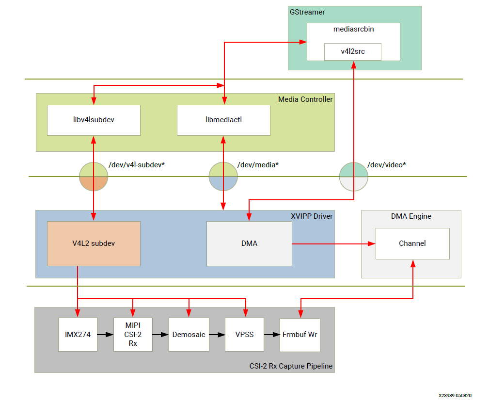
Video Capture Software Stack
At a high level it consists of the following layers from top to bottom:
- User-space layers
- GStreamer: Media source bin plugin (wrapper around generic v4l2src plugin)
- Media controller: Library to configure v4l subdevices and media devices
- Kernel-space layers
- V4L2/Media subsystems: Xilinx video IP pipeline (XVIPP) driver
- DMA engine: Xilinx framebuffer driver
5.1.2.1. Media Source Bin GStreamer Plugin
The mediasrcbin plugin is designed to simplify the usage of live video capture devices in this design, otherwise the user must take care of initialization and configuration. The plugin is a bin element that includes the standard v4l2src GStreamer element. It configures the media pipelines of the supported video sources in this design.
The v4l2src element inside the mediasrcbin element interfaces with the V4L2 Linux framework and the Xilinx VIPP driver through the video device node. The mediasrcbin element interfaces with the Media Controller Linux framework through the v412-subdev and media device nodes which allows you to configure the media pipeline and its sub-devices. It uses the libmediactl and libv4l2subdev libraries which provide the following functionality:
- Enumerate entities, pads and links
- Configure sub-devices
- Set media bus format
- Set dimensions (width/height)
- Set frame rate
- Export sub-device controls
The mediasrcbin plugin sets the media bus format and resolution on each sub-device source and sink pad for the entire media pipeline. The formats between pads that are connected through links need to match. Refer to the Media Framework section below for more information on entities, pads and links.
5.1.2.1.1. Kernel Subsystems
In order to model and control video capture pipelines such as the ones used in this TRD on Linux systems, multiple kernel frameworks and APIs are required to work in concert. For simplicity, we refer to the overall solution as Video4Linux (V4L2) although the framework only provides part of the required functionality. The individual components are discussed in the following sections.
5.1.2.2. Driver Architecture
The Video Capture Software Stack figure in the Capture section shows how the generic V4L2 driver model of a video pipeline is mapped to the single-sensor MIPI CSI-2 Rx capture pipelines. The video pipeline driver loads the necessary sub-device drivers and registers the device nodes it needs, based on the video pipeline configuration specified in the device tree. The framework exposes the following device node types to user space to control certain aspects of the pipeline:
- Media device node: /dev/media*
- Video device node: /dev/video*
- V4L2 sub-device node: /dev/v4l-subdev*
5.1.2.3. Media Framework
The main goal of the media framework is to discover the device topology of a video pipeline and to configure it at run-time. To achieve this, pipelines are modeled as an oriented graph of building blocks called entities connected through pads.
An entity is a basic media hardware building block. It can correspond to a large variety of blocks such as physical hardware devices (e.g. image sensors), logical hardware devices (e.g. soft IP cores inside the PL), DMA channels or physical connectors. Physical or logical devices are modeled as sub-device nodes and DMA channels as video nodes.
A pad is a connection endpoint through which an entity can interact with other entities. Data produced by an entity flows from the entity’s output to one or more entity inputs. A link is a point-to-point oriented connection between two pads, either on the same entity or on different entities. Data flows from a source pad to a sink pad.
A media device node is created that allows the user space application to configure the video pipeline and its sub-devices through the libmediactl and libv4l2subdev libraries. The media controller API provides the following functionality:
- Enumerate entities, pads and links
- Configure pads
- Set media bus format
- Set dimensions (width/height)
- Configure links
- Enable/disable
- Validate formats
The following figures show the media graphs for MIPI CSI-2 Rx (single-sensor and quad-sensor) as well as the HDMI Rx video capture pipeline as generated by the media-ctl utility. The subdevices are shown in green with their corresponding control interface base address and subdevice node in the center. The numbers on the edges are pads and the solid arrows represent active links. The yellow boxes are video nodes that correspond to DMA channels, in this case write channels (outputs).
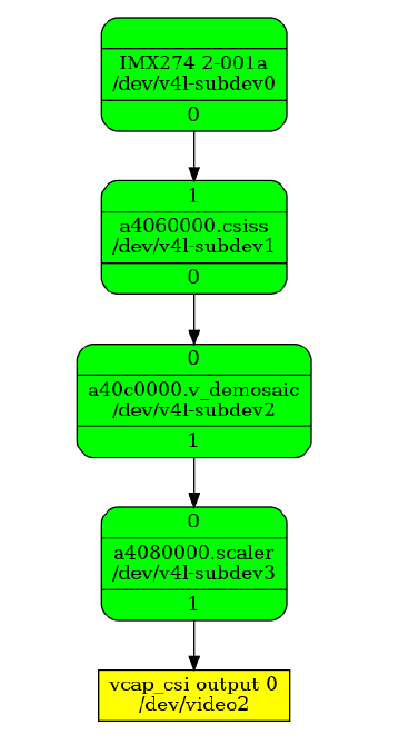
Video Capture Media Pipeline: Single MIPI CSI-2 RX
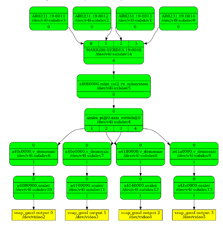
Video Capture Media Pipeline: Quad MIPI CSI-2 RX
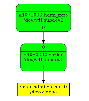
Video Capture Media Pipeline: HDMI RX
5.1.2.4. V4L2 Framework
The V4L2 framework is responsible for capturing video frames at the video device node, typically representing a DMA channel, and making those video frames available to user space. The framework consists of multiple sub-components that provide certain functionality.
Before video frames can be captured, the buffer type and pixel format need to be set using the VIDOC_S_FMT ioctl. On success the driver can program the hardware, allocate resources, and generally prepare for data exchange. Optionally, you can set additional control parameters on V4L devices and sub-devices. The V4L2 control framework provides ioctls for many commonly used, standard controls such as brightness and contrast.
The videobuf2 API implements three basic buffer types but only physically contiguous memory is supported in this driver because of the hardware capabilities of the Frame Buffer Write IP. Videobuf2 provides a kernel internal API for buffer allocation and management as well as a userspace facing API. VIDIOC_QUERYCAP and VIDIOC_REQBUFS ioctls are used to determine the I/O mode and memory type. In this design, the streaming I/O mode in combination with the DMABUF memory type is used.
DMABUF is dedicated to sharing DMA buffers between different devices, such as V4L devices or other video-related devices such as a DRM display device (see the GStreamer Pipeline Control section). In DMABUF, buffers are allocated by a driver on behalf of an application. These buffers are exported to the application as file descriptors.
For capture applications, it is customary to queue a number of empty buffers using the VIDIOC_QBUF ioctl. The application waits until a filled buffer can be de-queued with the VIDIOC_DQBUF ioctl and re-queues the buffer when the data is no longer needed. To start and stop capturing applications, the VIDIOC_STREAMON and VIDIOC_STREAMOFF ioctls are used.
The ioctls for buffer management, format and stream control are implemented inside the v4l2src plugin and the application developer does not need to know the implementation details.
5.1.2.5. Video IP Drivers
Xilinx adopted the V4L2 framework for most of its video IP portfolio. The currently supported video IPs and corresponding drivers are listed under V4L2. Each V4L driver has a sub-page that lists driver-specific details and provides pointers to additional documentation. The following table provides a quick overview of the drivers used in this design.
Table : V4L2 Drivers Used in Capture Pipelines
| Linux Driver | Function |
|---|---|
| Xilinx Video Pipeline (XVIPP) |
|
| Xilinx Video Processing Subsystem (Scaler Only configuration) |
|
| MIPI CSI-2 Rx |
|
| Xilinx Video Image Signal Processing (ISP) |
|
| Sony IMX274 Image Sensor |
|
| OnSemi AR0231 Image Sensor |
|
| MAX9286 GMSL Deserializer |
|
| AXI-Stream Switch |
|
| HDMI Rx Subsystem |
|
5.1.3. Display
The Display software stack is depicted in the following figure.
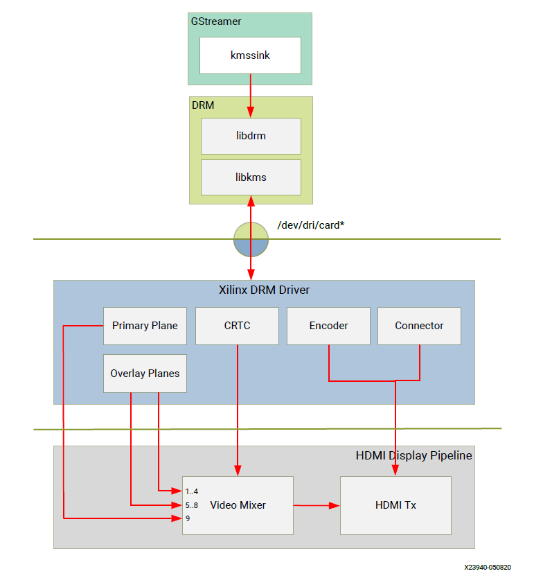
Display Software Stack
At a high-level it consists of the following layers from top to bottom which are further described in the next sections:
- User-space layers
- GStreamer: KMS sink plugin
- libdrm: DRM user-space library
- Kernel-space layers
- DRM/KMS subsystem: Xilinx DRM driver
- DMA engine: Xilinx framebuffer driver
5.1.3.1. KMS Sink GStreamer Plugin
The kmssink element interfaces with the DRM/KMS Linux framework and the Xilinx DRM driver through the libdrm library and the dri-card device node.
The kmssink element library uses the libdrm library to configure the cathode ray tube controller (CRTC) based on the monitor’s extended display identification data (EDID) information with the video resolution of the display. It also configures plane properties such as the alpha value.
5.1.3.2. Libdrm
The DRM/KMS framework exposes two device nodes to user space: the /dev/dri/card* device node and an emulated /dev/fb* device node for backward compatibility with the legacy fbdev Linux framework. The latter is not used in this design. libdrm was created to facilitate the interface of user space programs with the DRM subsystem. This library is merely a wrapper that provides a function written in C for every ioctl of the DRM API, as well as constants, structures and other helper elements. The use of libdrm not only avoids exposing the kernel interface directly to user space, but presents the usual advantages of reusing and sharing code between programs.
5.1.3.3. DRM/KMS Kernel Subsystem
Linux kernel and user-space frameworks for display and graphics are intertwined and the software stack can be quite complex with many layers and different standards/APIs. On the kernel side, the display and graphics portions are split with each having their own APIs. However, both are commonly referred to as a single framework: DRM/KMS.
This split is advantageous, especially for SoCs that often have dedicated hardware blocks for display and graphics. The display pipeline driver responsible for interfacing with the display uses the kernel mode setting (KMS) API and the GPU responsible for drawing objects into memory uses the direct rendering manager (DRM) API. Both APIs are accessed from user-space through a single device node.
A brief overview of the DRM is provided but the focus is on KMS as there is no GPU present in the design.
5.1.3.4. Direct Rendering Manager
The Xilinx DRM driver uses the GEM (Graphics Execution Manager) memory manager and implements DRM PRIME buffer sharing. PRIME is the cross-device buffer sharing framework in DRM. To user-space PRIME buffers are DMABUF-based file descriptors. The DRM GEM/CMA helpers use the Continuous Memory Access (CMA) allocator as a means to provide buffer objects that are physically contiguous in memory. This is useful for display drivers that are unable to map scattered buffers via an I/O memory management unit (IOMMU).
Frame buffers are abstract memory objects that provide a source of pixels to scan out to a CRTC. Applications explicitly request the creation of frame buffers and receive an opaque handle that can be passed to the KMS CRTC control, plane configuration, and page flip functions.
5.1.3.5. Kernel Mode Setting
Mode setting is an operation that sets the display mode including video resolution and refresh rate. It was traditionally done in user-space by the X-server which caused a number of issues due to accessing low-level hardware from user-space which, if done wrong, can lead to system instabilities. The mode setting API was added to the kernel DRM framework, hence the name kernel mode setting.
The KMS API is responsible for handling the frame buffer and planes, setting the mode, and performing page-flips (switching between buffers). The KMS device is modeled as a set of planes, CRTCs, encoders, and connectors as shown in the Display Software Stack figure in the Display section. The figure also shows how the driver model maps to the physical hardware components inside the HDMI Tx display pipeline
5.1.3.6. CRTC
CRTC is an antiquated term that stands for cathode ray tube controller, which today would be simply named display controller as CRT monitors have disappeared and many other display types are available. The CRTC is an abstraction that is responsible for composing the frame to be scanned out to the display and setting the mode of the display.
In the Xilinx DRM driver, the CRTC is represented by the video mixer. The bottom-most plane is the primary plane (or master layer) and configured statically in the device-tree. The primary plane always matches the currently configured display resolution set by the CRTC (width and height) with X- and Y-offsets set to 0. The primary plane can be overlayed with up to eight overlay planes inside the video mixer.
5.1.3.7. Plane
In this design, the primary plane can be overlayed and/or alpha-blended with up to eight additional planes inside the video mixer. The z-order (foreground or background position) of the planes is fixed. The global alpha mode can be configured per plane through the driver by means of custom KMS properties: an alpha value of 0% (or 0) means the layer is fully transparent (invisible); an alpha value of 100% (or 255) means that the layer is fully opaque.
Each overlay plane’s width, height, X- and Y-offset is run-time programmable relative to the primary plane or CRTC which determines the display resolution. The pixel formats of the primary plane as well as the eight overlay planes are fixed: one BGR plane (primary) plus four YUY2 planes (overlay) plus four BGR planes (overlay) from bottom to top.
The Xilinx DRM driver supports the universal plane feature, therefore the primary plane and overlay planes can be configured through the same API. A page-flip is the operation that configures a plane with the new buffer index to be selected for the next scan-out. The new buffer is prepared while the current buffer is being scanned out and the flip typically happens during vertical blanking to avoid image tearing.
5.1.3.8. Encoder
An encoder takes pixel data from a CRTC and converts it to a format suitable for any attached connectors. There are many different display protocols defined, such as HDMI and DisplayPort. This design uses an HDMI transmitter implemented in the PL which sends the encoded video data to the HDMI GT Controller and PHY. The PHY serializes the data using the GTY transceivers in the PL before it goes out via the HDMI Tx connector on the board.
5.1.3.9. Connector
The connector models the physical interface to the display. The HDMI protocols use a query mechanism to receive data about the monitor resolution, and refresh rate by reading the extended display identification data (EDID) (see VESA Standard ) stored inside the monitor. This data can then be used to correctly set the CRTC mode. HDMI also supports hot-plug events to detect if a cable has been connected or disconnected as well as handling display power management signaling (DPMS) power modes.
5.1.4. Audio
Audio Advanced Linux Sound Architecture (ALSA) arranges hardware audio devices and their components into a hierarchy of cards, devices, and subdevices. It reflects the capabilities of the hardware as seen by ALSA.
ALSA cards correspond one-to-one to hardware sound cards. A card can be denoted by its ID or by a numerical index starting at zero. ALSA hardware access occurs at the device level. The devices of each card are enumerated starting from zero.
The audio software stack is depicted in the following figure.
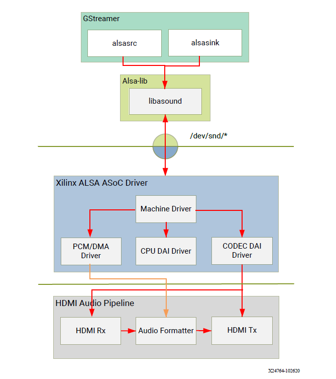
Audio Software Stack
At a high-level the audio software stack consists of the following layers from top to bottom:
- User-space layers
- GStreamer: alsasrc and alsasink plugins
- Alsa-lib: ALSA user-space library
- Kernel-space layers
- ALSA: Xilinx ALSA ASoC driver
5.1.4.1. ALSA Source and Sink GStreamer Plugins
The alsasrc plugin reads audio data from an audio card and the alsasink plugin renders audio samples using the ALSA API. The audio device is specified by means of the device property referring to the ALSA device as defined in an asound configuration file.
5.1.4.2. Alsa-lib
The ALSA library API is the interface to the ALSA drivers. Developers need to use the functions in this API to achieve native ALSA support for their applications. The currently designed interfaces are as follows:
- Information Interface (/proc/asound)
- Control Interface (/dev/snd/controlCX)
- Mixer Interface (/dev/snd/mixerCXDX)
- PCM Interface (/dev/snd/pcmCXDX)
- Raw MIDI Interface (/dev/snd/midiCXDX)
- Sequencer Interface (/dev/snd/seq)
- Timer Interface (/dev/snd/timer)
For more information, refer to https://www.alsa-project.org/alsa-doc/alsa-lib/.
5.1.4.3. ALSA Kernel Subsystem
A sound card, encapsulating playback and capture devices will be visible as single entity to the end user. There can be many playback and capture devices within a sound card and there can be multiple sound cards in a system.
The Machine driver creates a pipeline out of the ALSA drivers. This glue or DAI (Digital Audio Interface) link is made using registered device names or device nodes (using OF kernel framework). Each proper DAI link results as a device in a sound card. A sound card is thus a logical grouping of several such devices.
The Audio Formatter driver creates the platform device for the sound card. While creating the device, it passes the HDMI device tree node of either I2S/HDMI/SDI/SPDIF depending on the kind of sound card being created. When the sound card driver detects the kind of audio node (I2S/HDMI/SDI/SPDIF), the proper DAI link is selected from the available links.
HDMI Rx receives the data from the HDMI source and separates audio from the video content. The Xilinx Audio Formatter converts this AES data to PCM data and stores it in memory. HDMI TX gets the AES data from the Audio Formatter and embeds it into video.
The AES format contains PCM and channel status information. The Audio Formatter IP separates non-audio content such as channel status and stores it in registers. The Audio Formatter driver can parse the content of channel status to get audio parameters.
A dummy CPU DAI driver is used as there needs to be a CPU DAI to be registered with ASoC framework. Codec DAI will be part of HDMI Tx and Rx video drivers, as those provide and consume the digital audio data.
In this TRD design, a sound card is created with a record device for the HDMI-RX capture pipeline and a playback device for the HDMI-TX playback pipeline. The supported parameters are:
- Sampling rate: 48 kHz
- Sample width: 24 bits per sample
- Sample encoding: Little endian
- Number of channels: 2
- Supported format: S24_32LE
5.1.5. GStreamer
GStreamer is a cross-platform open source multimedia framework that provides infrastructure to integrate multiple multimedia components and create pipelines/graphs. GStreamer graphs are made of two or more plugin elements which are delivered as shared libraries. The following is a list of commonly performed tasks in the GStreamer framework:
- Selection of a source GStreamer plugin
- Selection of a processing VVAS plugin
- Selection of a sink GStreamer plugin
- Creation of a GStreamer graph based on above plugins plus capabilities
- Configuration of properties of above GStreamer plugins
- Control of a GStreamer pipeline/graph
5.1.5.1. Plugins
The following GStreamer plugin categories are used in this design:
- Source
- mediasrcbin: V4l2 sources such as USB webcam, MIPI single-sensor, MIPI quad-sensor
- multisrc/filesrc: video file source for raw or encoded image/video files
- Sink
- kmssink: KMS display sink for HDMI Tx
- filesink: video file sink for raw or encoded image/video files
- appsink: sink that makes video buffers available to an application such as the display inside jupyter notebooks
- Encode/decode
- jpegenc/dec: jpg image file encode/decode
- vp9enc/dec: vp9 video file encode/decode
- Processing/acceleration
- VVAS Infrastructure Plug-ins or VVAS Custom Plug-ins
- Other
- capsfilter: filters capabilities
- tee: tee element to create a fork in the data flow
- queue: creates separate threads between pipeline elements and adds additional buffering
- perf: measure frames-per-seconds (fps) at an arbitrary point in the pipeline
5.1.5.2. Capabilities
The pads are the element’s interface to the outside world. Data streams from one element’s source pad to another element’s sink pad. The specific type of media that the element can handle is exposed by the pad’s capabilities. The following capabilities are used between the video-source plugin and its peer plugin (either video-sink or video-processing). These capabilities (also called capsfilter) are specified while constructing a GStreamer graph, for example:
"video/x-raw, width=<width of videosrc>, height=<height of videosrc>,format=YUY2, ramerate=<fps/1>"
If multisrc is used as video-source plugin, the videoparse element is used instead of a capsfilter to parse the raw video file and transform it to frames:
"video/x-raw, width=<width of videosrc>, height=<height of videosrc>,format=YUY2, framerate=<fps/1>"
5.1.5.3. Pipeline Control
The GStreamer framework is used to control the GStreamer graph. It provides the following functionality:
- Start/stop video stream inside a graph
- Get/set controls
- Buffer operations
- Get frames-per-second information
There are four states defined in the GStreamer graph: “NULL”, “READY”, “PAUSED”, and “PLAYING”. The “PLAYING” state of a GStreamer graph is used to start the pipeline and the “NULL” state is to stop the pipeline.
5.1.5.4. Allocators
GStreamer abstracts buffer allocation and pooling. Custom allocators and buffer pools can be implemented to accommodate custom use-cases and constraints. The video source controls buffer allocation, but the sink can propose parameters in the negotiation phase.
The DMABUF framework is used to import and export buffers in a 0-copy fashion between
pipeline elements, which is required for high-performance pipelines, as shown in the following
figure. The v4l2src, kmssink, and ivas elements are all capable of
allocating and exporting as well as importing DMABUFs to/from their peer
elements.
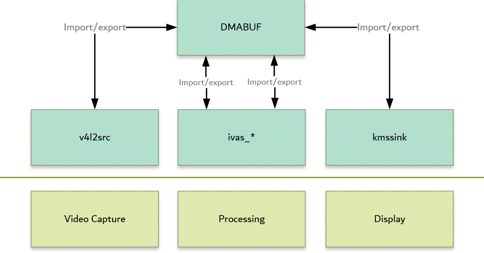
DMABUF Sharing Mechanism
Note that DMABUFs are not necessarily physically contiguous depending on the underlying kernel device driver, that is, the UVC v4l2 driver does not allocate CMA memory which results in a data copy if its peer element can only handle contiguous memory.
Licensed under the Apache License, Version 2.0 (the “License”); you may not use this file except in compliance with the License.
You may obtain a copy of the License at [http://www.apache.org/licenses/LICENSE-2.0](http://www.apache.org/licenses/LICENSE-2.0)
Unless required by applicable law or agreed to in writing, software distributed under the License is distributed on an “AS IS” BASIS, WITHOUT WARRANTIES OR CONDITIONS OF ANY KIND, either express or implied. See the License for the specific language governing permissions and limitations under the License.