2. Introduction
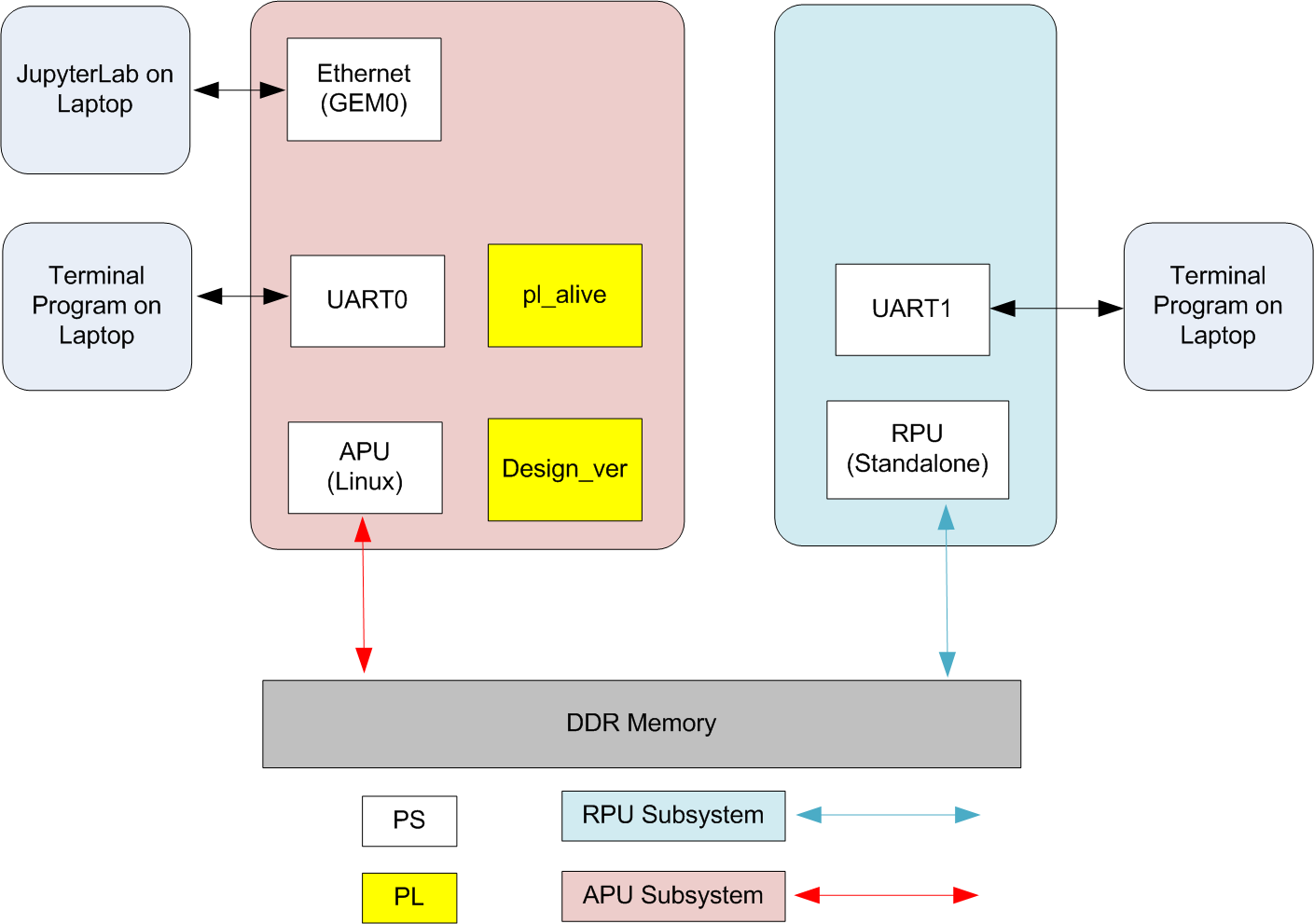
The Versal System and Subsystem Restart TRD (VSSR TRD), also referred to as Versal Restart TRD, demonstrates how to restart various components of a system. It also showcases the liveliness of a subsystem while another subsystem is undergoing restart.
The TRD consists of a baseline Vivado design, Petalinux, Jupyter notebooks and other software components to demonstrate different restart scenarios.
2.1. Features:
Subsystem definitions
APU subsystem running Linux
RPU Lockstep running a PM-aware standalone application.
Jupyter lab based user interface, with dashboard layout
Libmetal shared-memory communication channel between APU and RPU subsystem
Healthy boot monitoring for the subsystems
Watchdog monitoring for the subsystems after boot.
Demonstration of following restart scenarios:
Subsystem Restart for Linux system running on APU
Subsystem Restart for Standalone system running on RPU
System Restart by APU
System Restart by RPU
System recovery due to boot hang during Linux boot.
System recovery due to bad boot during Standalone RPU boot.
Subsystem recovery due to Linux hang (by forcing FPD watchdog expiry)
Subsystem recovery due to RPU hang (by forcing LPD watchdog expiry)
Supports multiple platforms:
2.2. Hardware Design
The base design is a simple example of an APU subsystem with a register-based PL design to allow the user to check if a PL subsystem was re-programmed or reset without the user actively issuing a reset. In the pl_alive module, there is register that uses the Power On Reset (POR) mechanism of the Versal device to set a register to a high value on initial power up. This register is reset to a low value by the APU writing to a register and should stay low as long as the PL is operational. There is also a pulse input to the module that acts as a heartbeat to the PL indicating that the APU is also alive. The pl_alive module takes this pulse signal and toggles an output port on the module which can be read by the APU to see that the PL is responding to the pulse signal. There is also an AXI GPIO module that has a fixed unique value for the software to read, which is used to detect the design version in the PL.
2.3. Subsystem Definition
The subsystem definition is important for the PLM to:
Identify a subsystem by its ID
Track the access permission of various peripheral for the subsystem
Make sure the pre-alloced peripherals are available when the subsystem is loaded.
Enable healthy boot monitoring for the subsystem.
The TRD defines two subsystems, APU Subsystem running Linux on SMP Cortex A72 cores and RPU Subsystem running standalone application on Lock-Step Cortex R5 cores.
Following table describes example of some peripheral permission for subsystems in the TRD:
Peripheral |
Subsystem |
Pre-alloced |
Access Permission |
|---|---|---|---|
Uart_0 |
APU |
Yes |
Shared |
Uart_1 |
RPU |
Yes |
Exclusive |
Sdio_1 |
APU |
Yes |
No Restriction |
Swdt_fpd |
APU |
No |
Time-shared |
Swdt_lpd |
RPU |
No |
Time-shared |
Gem_0 |
APU |
Yes |
Exclusive |
HB_MON_0 |
APU |
Yes |
Exclusive |
HB_MON_1 |
RPU |
Yes |
Exclusive |
Detail subsystem definition is available in the sources under hw/common/subsystem.cdo file.
Note
Uart_0 is set to have Shared access permission as it is being shared with plm for initial boot messages.
Note
Access permissions will be enforced both by hardware (using protection units) and software (using plm and pm permissions).
2.4. Software Stack
This section list the software pieces involved in demonstrating the TRD features.
Software |
Processor |
Function with respect to TRD use cases |
|---|---|---|
PLM |
PMC |
Controls various restarts and maintains the life cycle of the subsystem. |
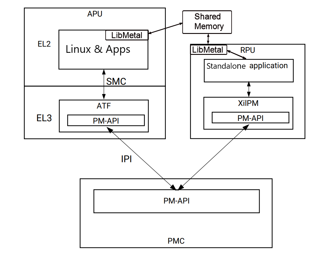
ATF |
APU |
Arm Trusted firmware (Running on ARM EL3) interacts directly with PLM (through IPI) for various PM activities, including restarts. Like all PM related requests, Linux’s system and subsystem restart requests are eventually handled by ATF. |
XilPm Client lib |
RPU LS |
This is the client side API library to issue PM requests to PLM. RPU application issues various PM requests, including restarts through this library to the PLM. |
Linux |
APU |
Hosts Jupyter Notebook server to demonstrate TRD features. It also manages various APU peripherals, including FPD WDT through the respective drivers. Linux Runs on ARM EL2. |
Standalone App |
RPU LS |
PM aware application with standalone OS. It uses standalone drivers to control various peripherals, like UART and LPD WDT. It also establish and uses libmetal shared memory based communication channel with APU. |
Note
There are other software pieces in the stack, like u-boot, psm-firmware, etc. but are not mentioned above as they don’t actively participates in TRD demonstration.
Below diagram shows relationship and interaction between above pieces:
Please refer Versal ACAP System Software Developers Guide for more details on software stack and detailed development guide for each component.
Refer to Restart Use Cases section in the Appendix for details on each of the TRD use cases and the software components involved.
2.5. Package
The reference design package contains of 2 parts:
Binaries
Pre-built binaries
Available in zip file for each board variant
Sources
Sources and build scripts to build hardware, software and documentation.
Available in the git repository.
2.5.1. Binaries
Download the zip file from Xilinx.com, for the specific board variant.
It has the following contents:
Pre-built SD card image
Artifacts from hardware and software builds under reference_images/
README file
The zip contents for vck190-prod are as follow
vssr-trd-pb-vck190-prod-2023.1.zip
│
vssr-trd-vck190-prod
├── LICENSE
├── prebuilt
│   ├── petalinux-sdimage.wic.xz
│   └── reference_images/
│       ├── bl31.elf
│       ├── boot.bif
│       ├── BOOT.BIN
│       ├── boot.scr
│       ├── Image
│       ├── plm.elf
│       ├── psmfw.elf
│       ├── ramdisk.cpio.gz.u-boot
│       ├── rootfs.tar.gz
│       ├── rpu_app.elf
│       ├── system.dtb
│       ├── u-boot.elf
│       ├── versal_restart_trd_wrapper.pdi
│       └── versal_restart_trd_wrapper.xsa
└── README
Same file structure is available for other variants (vmk180-prod) as well.
2.5.2. Sources
Sources for the TRD are available in the git repository. It provides:
Sources for the hardware design
Sources for the TRD yocto layer (used in Petalinux)
Sources for the standalone rpu application
Sources for the documentation
Makefiles and Scripts to build all the sources
Clone the git repository for the current release tag.
# Create and move to directory where the source repository is to be cloned
mkdir -p </path/to/source/repo>
cd </path/to/source/repo>

# clone and switch to current release tag (xilinx-v2023.1)
git clone https://github.com/Xilinx/versal-restart-trd.git
cd versal-restart-trd
git checkout -b xilinx-v2023.1 xilinx-v2023.1
From the cloned area, run make help to see various build options.
The repository directory structure is as follow:
versal-restart-trd
├── docs
│   ├── ... document sources
│   └── Makefile           # Documentation Makefile
├── hw
│   ├── common             # Common constraints and subsystem definition
│   ├── ip_repo
│   ├── Makefile           # Hardware Makefile
│   ├── vck190_prod_base   # sources for each variants
│   └── vmk180_prod_base
├── LICENSE
├── Makefile               # Top level Makefile
├── README.md
└── sw
    ├── Makefile           # Software Makefile
    ├── scripts            # Script to configure or build
    ├── standalone-srcs    # Rpu application sources
    └── yocto-layers       # Yocto layers to be included in TRD
2.6. Licenses
The design includes files licensed by Xilinx and third parties under the terms of the GNU General Public License, GNU Lesser General Public License, BSD License, MIT License, and other licenses.
Licenses for rootfs files are included in the /usr/share/licenses directory when the image file is built. DNF package manager can be used to list all packages in the image as well as download all the sources for all the packages.
LICENSE file included the prebuilt image’s zip file details the licenses of the packages used in the prebuilt images.
You are solely responsible for checking any files you use for notices and licenses and for complying with any terms applicable to your use of the design sl-restart-trdss any third party files supplied with the design.

