Using the RTL Kernel Wizard
Introduction
This lab guides you through the steps involved in using the Vitis RTL Kernel wizard. This allows RTL code to be used in a Vitis design. To do so, it uses a vector addition kernel written in Verilog.
Objectives
After completing this lab, you will be able to:
- Understand how to use the RTL Kernel wizard available in Vitis
- Create a new RTL based IP
- Add the new IP to an application
- Verify the functionality of the design in hardware
Steps
Create a Vitis Project
-
Start Vitis and select the default workspace (or continue with the workspace from the previous lab)
-
Create a new application project
Use
Create Application Projectfrom Welcome page, or useFile > New > Application Projectto create a new application -
Select your target platform and click Next >
If you don’t see your target platform, then click on ‘+’ button, browse to directory where platform is located and click OK
-
In the Application Project Details page enter rtl_kernel in the Application Project name: field and click Next >
-
Select Empty Application and click Finish
Create RTL_Kernel Project using RTL Kernel Wizard
-
Make sure the rtl_kernel.prj under rtl_kernel_system > rtl_kernel in the Explorer view is selected
-
In the menu bar on top click Xilinx > Launch RTL Kernel Wizard > rtl_kernel_kernels
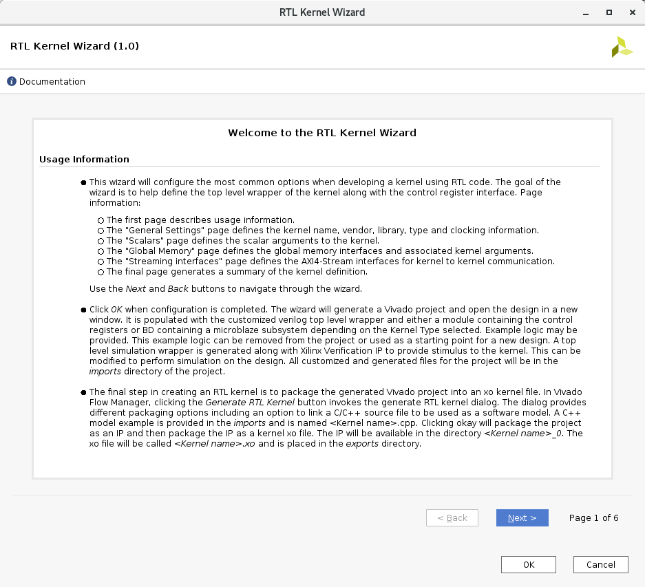
Wizard will be opened showing welcome package
-
In the Welcome page click Next >
-
Change
Kernelname to KVAdd, (for Kernel Vector Addition),Kernel vendorto xilinx.com leaving theKernel library,Kernel type,Kernel control interface,Number of clocksandHas resetto the default values. Then click Next >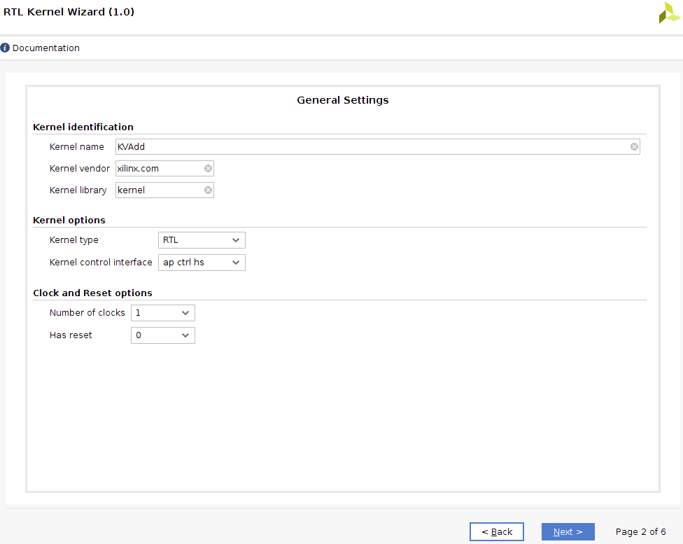
-
Leave
Number of scalar kernel input argumentsset to the default value of 1,Argument Nameset to the default value of scalar00 and theArgument typeas uint, and click Next >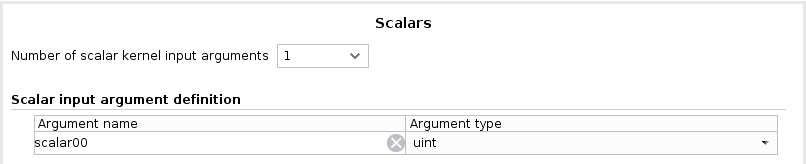
-
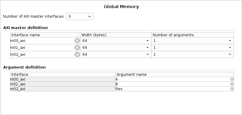
We will have three arguments to the kernel (2 inputs and 1 output) which will be passed through Global Memory. Set
Number of AXI master interfacesto be 3Keep the width of each AXI master data width to 64 (note this is specified in bytes so this will give a width of 512 bits for each interface). Update the arguments name: A for m00_axi, B for m01_axi, and Res for m02_axi
-
Click Next > and Stream Interface page will be displayed. Notice: this example does not use AXI4-Stream interfaces. Therefore, make sure that
Number of AXI4-Stream interfacesis set to 0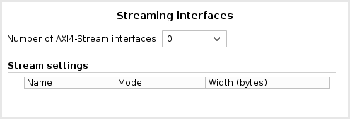
-
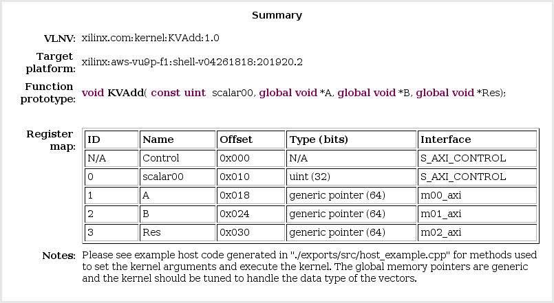
Click Next > and the the Summary page will be displayed showing a function prototype and register map for the kernel.
Note the control register and the scalar operand are accessed via the S_AXI_CONTROL interface. The control register is at offset 0x0 and the scalar operand is at offset 0x10
-
Click OK to close the wizard
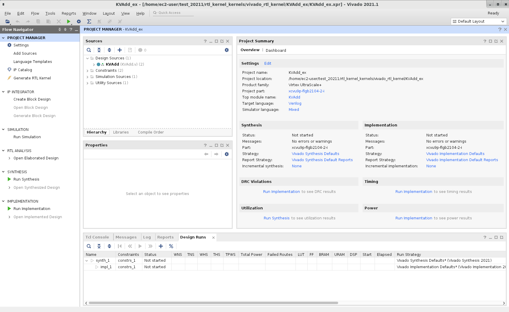
Notice that a Vivado Project will be created and opened after few seconds
Analyze the design created by the RTL Kernel wizard
-
Expand the hierarchy of the Design Sources in the Sources window and notice all the design sources, constraint file, and the basic testbench generated by the wizard
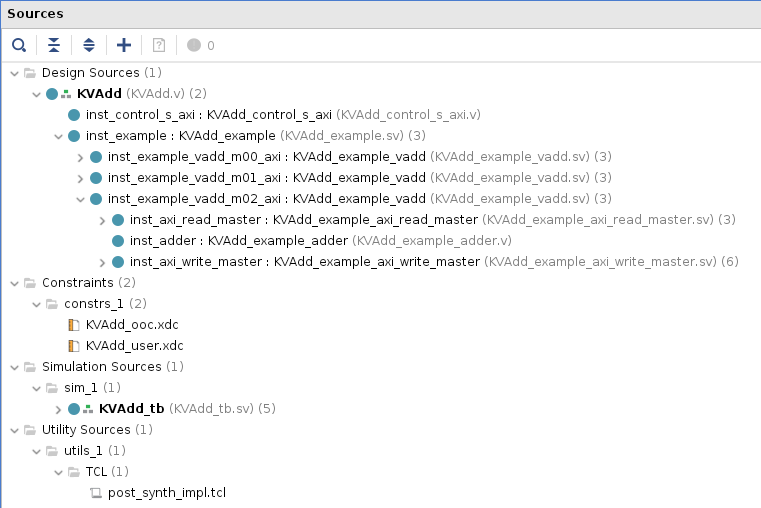
There is one module to handle the control signals (ap_start, ap_done, and ap_idle) and three master AXI channels to read source operands from, and write the result to DDR. The expanded m02_axi module shows read, adder, write instances
-
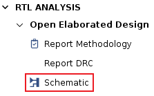
Expand Flow Navigator > RTL ANALYSIS > Open Elaborated Design and click on Schematic. Then, click OK
-
You should see two top-level blocks: example and control as seen below
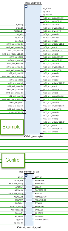
Notice the AXI Master interfaces are 64 bytes (or 512 bits) wide as specified earlier
-
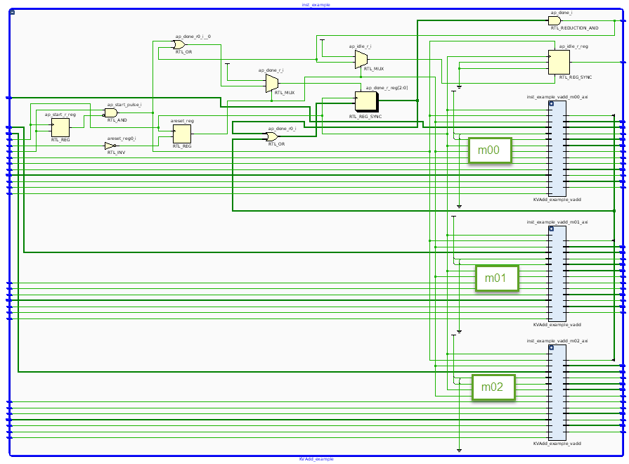
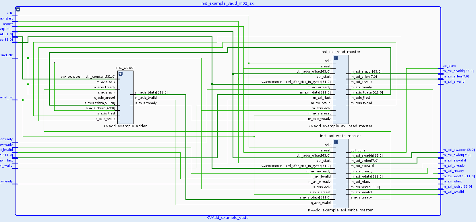
Double-click on the example block and observe the three hierarchical Master AXI blocks
-
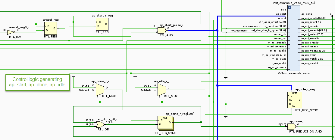
Zoom in into the top section and see the control logic, the wizard has generated the ap_start, ap_idle, and ap_done control signals
-
Traverse through one of the AXI interface blocks (e.g. m02) and observe that the design consists of a Read Master, Write Master, and an Adder. (Click on the image to download an enlarged version if necessary)
-
Close the elaborated view by selecting File > Close Elaborated Design
-
Click OK
Generate the RTL Kernel
-
Select Flow > Generate RTL Kernel… or click Generate RTL Kernel in the left-hand side pane
-
Click OK using the default option (Sources-only kernel)
The packager will be run, generating the xo file which will be used in the design
-
Click OK, then Yes to exit Vivado
-
Click OK on the message box indicating that the RTL Kernel has been imported and return to Vitis
Analyze the RTL kernel added to the Vitis project
-
Expand the src folder under the rtl_kernel_system > rtl_kernel_kernels
Notice that the vitis_rtl_kernel folder has been added to the project. Expanding this folder (KVAdd) shows the kernel (.xo) and a C++ file which have been automatically included
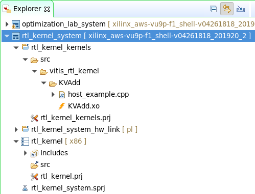
- Double-click on the host_example.cpp to open it
- The main function is defined around line 67. The number of words it transfers is 4,096
- Notice around line 96 the source operands and expected results are initialized
- Around line 214 (from the
clCreateProgramWithBinary()function) shows the loading of the xclbin and creating the OpenCL kernel (clCreateKernel()) - The following lines (~255) show how the buffers are created in the device memory and enqueued (
clCreateBuffer(),clEnqueueWriteBuffer()) - Around lines 310, the arguments to the kernel are set (
clSetKernelArg()), and the kernel is enqueued to be executed (clEnqueueTask()) - Around line 343 results are read back (
clEnqueueReadBuffer()) and compared to the expected results. - The Shutdown and cleanup section shows releasing of the memory, program, and kernel
-
If you are using a platform that is not AWS F1, make the following changes in the host_example.cpp code
-
Replace line 84
char target_device_name[1001] = TARGET_DEVICE;with the followingchar target_device_name[1001] = TARGET_DEVICE; target_device_name[23] = '\0'; -
Replace line 163
if(strcmp(cl_device_name, target_device_name) == 0) {with the followingif(strstr(cl_device_name, target_device_name) != NULL){
-
Define a hardware kernel, and build the project
-
Import the host_example.cpp file from rtl_kernel_system > rtl_kernel_kernels > src > vitis_rtl_kernel > KVAdd into the rtl_kernel_system > rtl_kernel > src folder
This is necessary as the host compiler expects the application source(s) in this folder
-
Select rtl_kernel_kernels.prj in the Explorer view to see the project settings page
-
Click on the Add Hardware Function button (
 ) and select KVAdd
 -
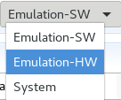
Select Emulation-HW on the drop-down button of Active build configuration:
-
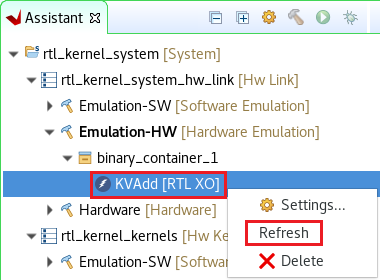
In the Assistant View, expand rtl_kernel_system > rtl_kernel_system_hw_link > Emulation-HW > binary_container_1 and right-click KVAdd [RTL KO] and select Refresh
-
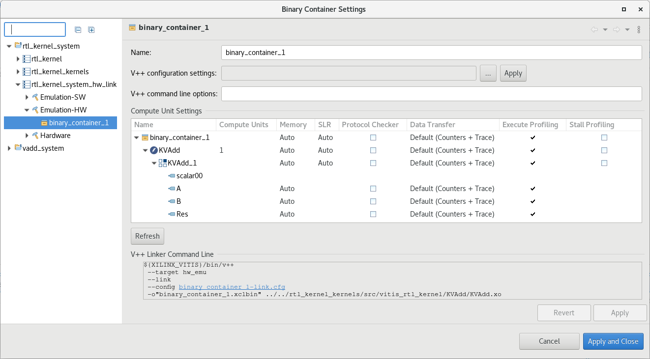
In the Assistant view right click on rtl_kernel_system > rtl_kernel_system_hw_link > Emulation-HW > binary_container_1 and select Settings…
Make sure the binary_container_1 is configured as shown in the image below
-
Select
rtl_kernel_systemin the Assistant view and build the project by clicking on the ( ) button
This will build the project including rtl_kernel executable file under the Emulation-HW directory. It may take about 10 minutes to build
-
Select rtl_kernel_system in the Assistant view and select Run > Run Configurations… to open the configurations window
-
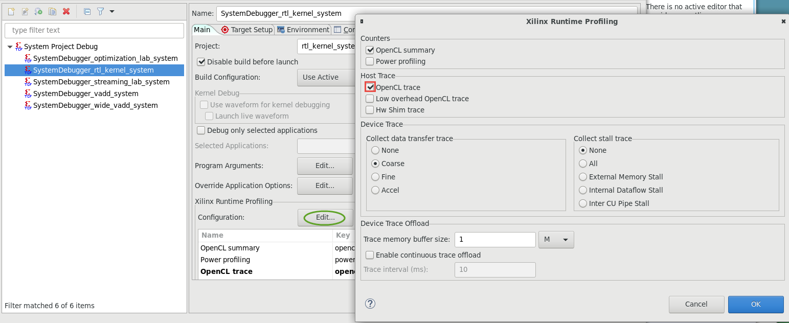
Make sure to check the OpenCL trace option of the Host trace by clicking the Edit… button of the Xilinx Runtime Profiling
-
Click Apply, and then click Run to run the application
-
The Console tab shows that the test was completed successfully along with the data transfer rate
Note that three memory controllers are used, all of which targeting to the same DDR
INFO: Found 1 platforms INFO: Selected platform 0 from Xilinx INFO: Found 1 devices CL_DEVICE_NAME xilinx_aws-vu9p-f1_shell-v04261818_201920_2 Selected xilinx_aws-vu9p-f1_shell-v04261818_201920_2 as the target device INFO: loading xclbin ../binary_container_1.xclbin INFO: [HW-EM 01] Hardware emulation runs simulation underneath.... INFO: Test completed successfully. INFO::[ Vitis-EM 22 ] [Time elapsed: 0 minute(s) 30 seconds, Emulation time: 0.151515 ms] Data transfer between kernel(s) and global memory(s) KVAdd_1:m00_axi-DDR[1] RD = 16.000 KB WR = 16.000 KB KVAdd_1:m01_axi-DDR[1] RD = 16.000 KB WR = 16.000 KB KVAdd_1:m02_axi-DDR[1] RD = 16.000 KB WR = 16.000 KB -
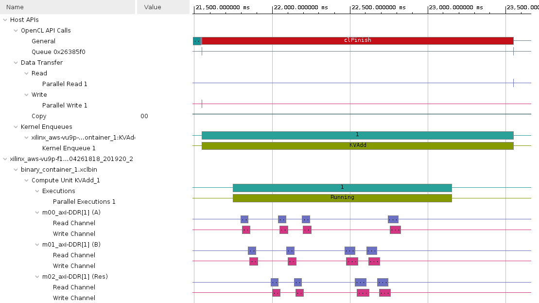
In the Assistant view, expand rtl_kernel_system > rtl_kernel > Emulation-HW > SystemDebugger_rtl_kernel_system_rtl_kernel, and double-click on Run Summary (xclbin)
-
The Vitis Analyzer window will open. Click on Timeline Trace entry, expand all entries in the timeline graph, zoom appropriately and observe the transactions
Build system hardware with profiling and timing analysis options if are continuing with the lab OTHERWISE skip to Prebuilt
-
Set
Active build configuration:toHardwareon the upper right corner of Application Project Settings viewIn order to collect the profiling data and run Timing Analyzer on the application run in hardware, we need to setup some options.
-
Select
rtl_kernel_system > rtl_kernel_system_hw_link > Hardware > binary_container_1in Assistant view and then click on Settings. Notice that the settings from the Emulation-HW run have propagated to the Hardware configuration. -
Select Trace Memory to be FIFO type and size of 64K
-
Click Apply and Close
-
Build the project by selecting rtl_kernel_system in
Assistantview and clicking the build button -
A
binary_container_1.xclbinandoptimization_labapplication will be generated in thertl_kernel/Hardwaredirectory -
Register the generated xclbin file to generate binary_container_1.awsxclbin by running the shell script. Follow instructions available here
Run the system in hardware
-
If you have built the hardware yourself then copy the necessary files using the following commands:
cp binary_container_1.awsxclbin ~/workspace/rtl_kernel/Hardware cp ~/xup_compute_acceleration/sources/xrt.ini ~/workspace/rtl_kernel/Hardware/. -
If you have not built the hardware yourself then copy the provided prebuilt solution files using the following commands:
mkdir ~/workspace/rtl_kernel/Hardware mkdir ~/workspace/rtl_kernel_system/Hardware cp ~/xup_compute_acceleration/solutions/rtlkernel_lab/* ~/workspace/rtl_kernel/Hardware/ cp ~/xup_compute_acceleration/solutions/rtlkernel_lab/binary_container_1.awsxclbin ~/workspace/rtl_kernel_system/Hardware/binary_container_1.xclbin chmod +x ~/workspace/rtl_kernel/Hardware/rtl_kernel -
Execute precompiled hardware solution
cd ~/workspace/rtl_kernel/Hardware/
./rtl_kernel binary_container_1.awsxclbin
The FPGA bitstream will be downloaded and the host application will be executed showing output similar to:
INFO: Found 1 platforms
INFO: Selected platform 0 from Xilinx
INFO: Found 1 devices
CL_DEVICE_NAME xilinx_aws-vu9p-f1_shell-v04261818_201920_2
Selected xilinx_aws-vu9p-f1_shell-v04261818_201920_2 as the target device
INFO: loading xclbin binary_container_1.awsxclbin
INFO: Test completed successfully.
Analyze hardware application timeline and profile summary
-
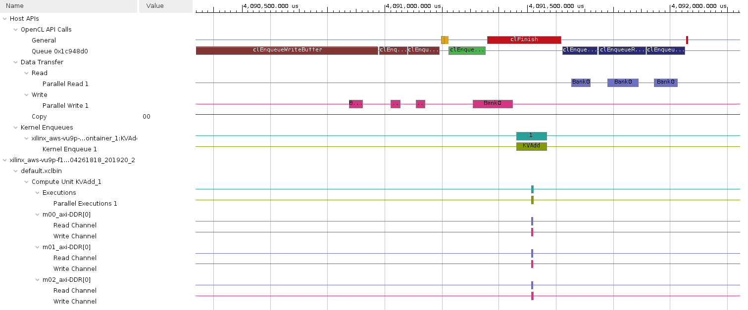
Execute the following command to open Vitis Analyzer and click Application Timeline
vitis_analyzer xclbin.run_summary -
Zoom in into the tail end of the execution and see various activities
-
Now click on Profile Summary
- Kernels & Compute Units
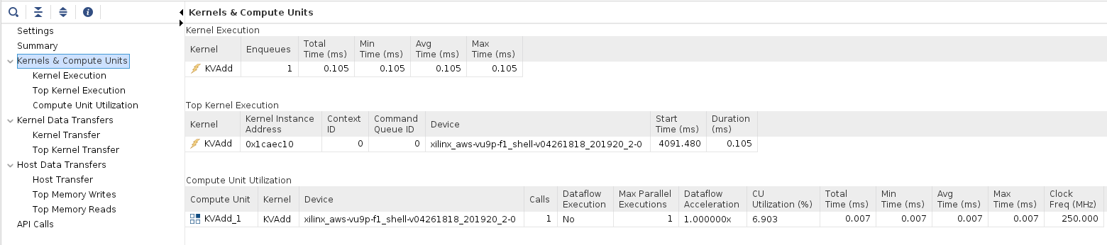
- Kernel Data Transfers
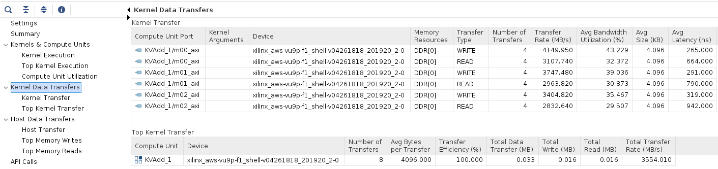
- Host Data Transfer
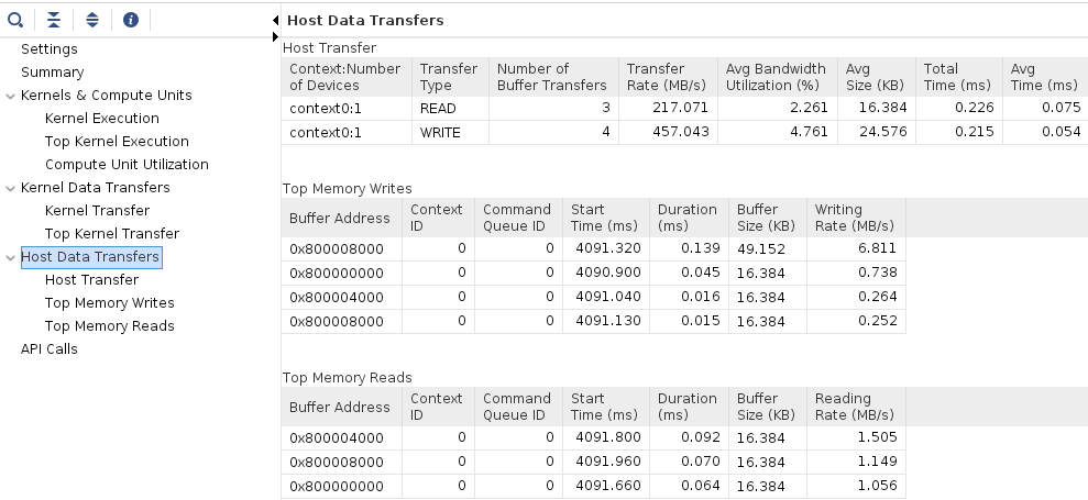
-
When finished, close the analyzer by clicking
File > Exitand clicking OK
Conclusion
In this lab, you used the RTL Kernel wizard to create an example RTL adder kernel. You configured the template and saw the example code that was automatically generated. You performed HW emulation and analyzed the application timeline.
Copyright© 2021 Xilinx