Adding Custom IP to the System
Objectives
After completing this lab, you will be able to:
- Use the IP Packager feature of Vivado to create a custom peripheral.
- Modify the functionality of the IP.
- Add the custom peripheral to your design.
- Add pin location constraints.
- Add block memory to the system.
Steps
Create a Custom IP using the Create and Package IP Wizard
- Open Vivado by selecting Start > All Programs > Xilinx Design Tools > Vivado 2021.2 > Vivado 2021.2.
- Click Manage IP and select New IP Location and click Next in the New IP Location window.
- Click on the browse button for the Part section. Click on boards and select the PYNQ-Z2 as your part. Click OK.
-
Select Verilog as the Target Language, Mixed as the Simulator language, and for IP location, type {labs}\led_ip and click Finish (leave other settings as defaults and click OK if prompted to create the directory)
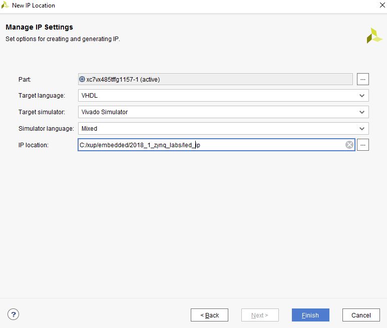
New IP Location form (**Needs to be Updated**)
Run the Create and Package IP Wizard
- Select Tools > Create and Package New IP.
- In the window, click Next.
- Select Create a new AXI4 peripheral, and click Next.
-
Fill in the details for the IP.
Name: led_ip
Display Name: led_ip_v1_0
(Fill in a description, Vendor Name, and URL)
- Click Next.
- Change the Name of the interface to S_AXI.
-
Leave the other settings as default and click Next (Lite interface, Slave mode, Data Width: 32, Number of Registers: 4).
- Select Edit IP and click Finish (a new Vivado Project will open).
Create an interface to the LEDs
-
In the sources panel, double-click the led_ip_v1_0.v file.
This file contains the HDL code for the interface(s) selected above. The top level file contains a module which implements the AXI interfacing logic, and an example design to write to and read from the number of registers specified above. This template can be used as a basis for creating custom IP. A new parameterized output port to the LEDs will be created at the top level of the design, and the AXI write data in the sub-module will be connected back up to the external LED port.
Scroll down to line 7 where a user parameters space is provided.
-
Add the line:
parameter integer LED_WIDTH = 8, -
Go to line 18 and add the line:
output wire [LED_WIDTH-1:0] LED,don’t forget to add commas when adding a port.
- Insert the following at line ~48:
.LED_WIDTH(LED_WIDTH), - Insert the following at line ~52:
.LED(LED), - Save the file by selecting File > Save File.
- Expand led_ip_v1_0 in the sources view if necessary, and open led_ip_v1_0_S_AXI.v.
-
Add the LED parameter and port to this file too, at lines 7 and 18 (done in steps 2 ands 3).
-
Scroll down to ~line 400 and insert the following code to instantiate the user logic for the LED IP. (This code can be typed directly, or copied from the user_logic_instantiation.txt file in the lab3 source folder.)
lab3_user_logic  # (
    .LED_WIDTH(LED_WIDTH)
)
U1(
    .S_AXI_ACLK(S_AXI_ACLK),
    .slv_reg_wren(slv_reg_wren),
    .axi_awaddr(axi_awaddr[C_S_AXI_ADDR_WIDTH-1:ADDR_LSB]),
    .S_AXI_WDATA(S_AXI_WDATA),
    .S_AXI_ARESETN(S_AXI_ARESETN),
    .LED(LED)
);
Check all the signals that are being connected and where they originate.
- Save the file by selecting File > Save File.
-
Click on the Add Sources in the Flow Navigator pane, select Add or Create Design Sources, click Next, then click the Plus icon then Add Files…, browse to {sources}\lab3, select the lab3_user_logic.v file and click OK, and then click Finish to add the file.
Check the contents of this file to understand the logic that is being implemented. Notice the formed hierarchy.
Make sure that when adding the source lab3_user_logic.v, untick the option: Copy sources into IP directory.
- Click Run Synthesis and Save if prompted. (This is to check the design synthesizes correctly before packaging the IP. If this was your own design, you would simulate it and verify functionality before proceeding)
-
Check the Messages tab for any errors and correct if necessary before moving to the next step
When Synthesis completes successfully, click Cancel.
Package the IP
- Click on the Package IP – led_ip tab
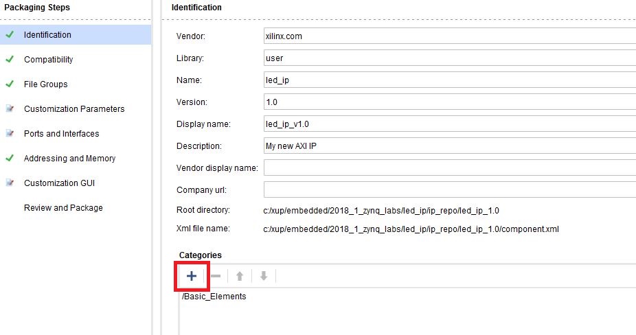
Package IP
Skip the next two steps (2 and 3) if you see /Basic_Elements under the Categories section, (like the one shown in figure)
- For the IP to appear in the IP catalog in particular categories, the IP must be configured to be part of those categories. To change which categories the IP will appear in the IP catalog click Blue Plus (Red box shown in the figure) in the Categories section. This opens the Choose IP Categories window
- For the purpose of this exercise, uncheck the AXI Peripheral box and check the Basic Elements and click OK.
- Select Compatibility. This shows the different Xilinx FPGA Families that the IP supports. The value is inherited from the device selected for the project during creating the IP.
- You should have something like this:
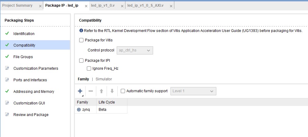
Compatibility under Package IP
If this does not match up with what you have, click the blue plus then Add Family Explicitly… from the menu. Select the Zynq family (This is the family of devices the PYNQ-Z2 belongs to) and click OK.
- You can also customize the address space and add memory address space using the Addressing and Memory category. We won’t make any changes this time.
-
Click on File Groups and click Merge changes from File Groups Wizard.
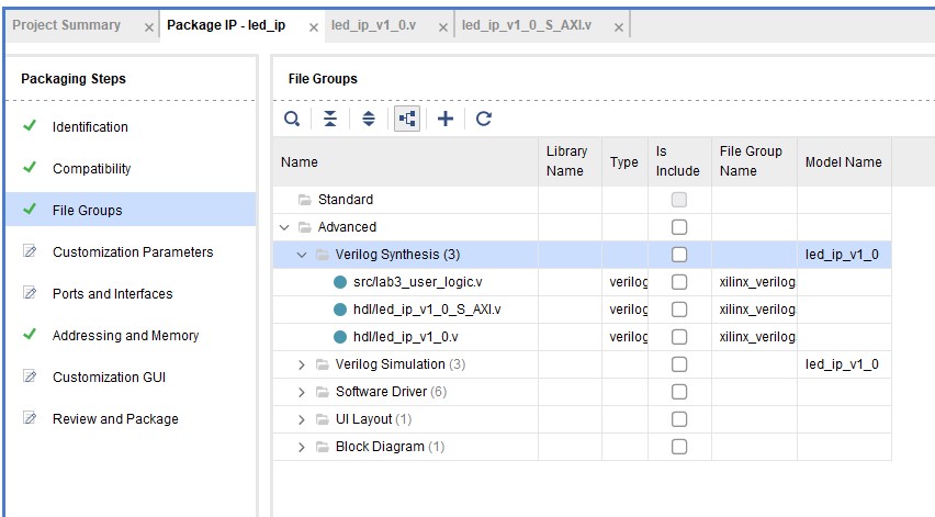
Compatibility under Package IP
This is to update the IP Packager with the changes that were made to the IP and the lab3_user_logic.v file that was added to the project. Expand Verilog Synthesis and notice lab3_user_logic.v has been included.
- Click on Customization Parameters and again Merge changes from Customization Parameters Wizard. Notice that the Ports and Interfaces view now shows the user created LED port
- Select Customization Parameters, expand Hidden Parameters, right-click on LED_WIDTH, and select Import IP Parameters… and click OK.
-
Select Customization GUI and notice that the Led Width is visible.
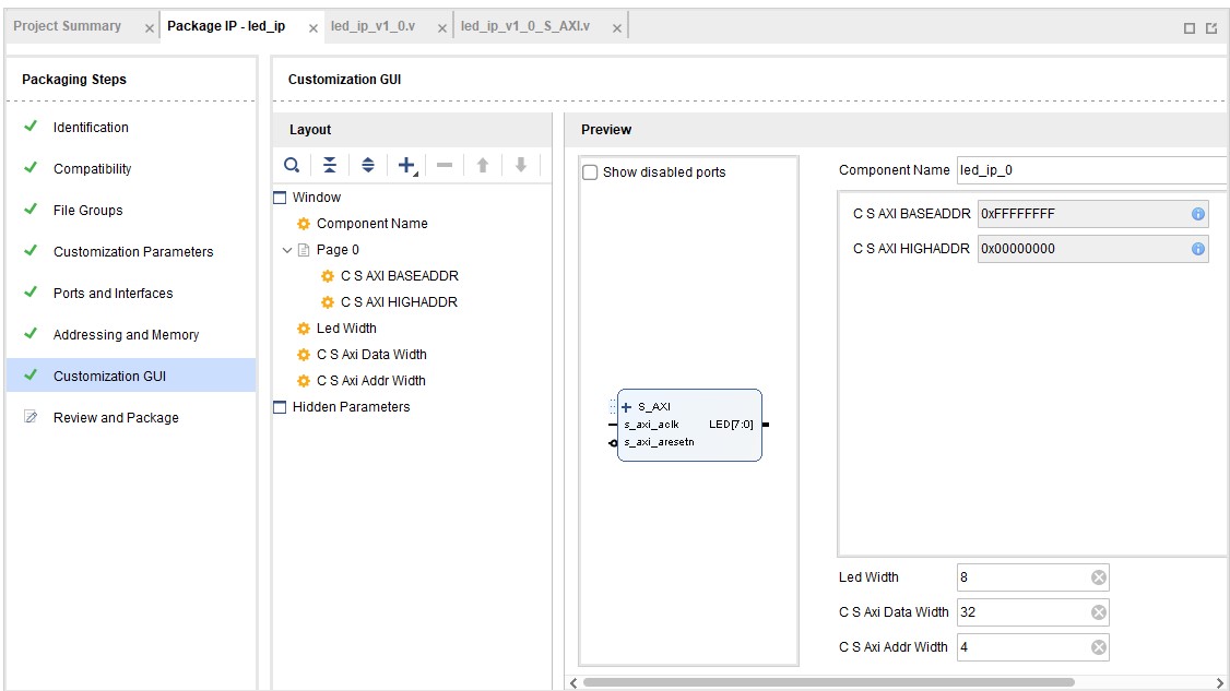
Customization GUI under Package IP
- Select Review and Package, and notice the path where the IP will be created.
- Click Re-Package IP. Click Yes and the project will close when complete.
- In the original Vivado window click File > Close Project.
Fix bugs for Windows
You may encounter errors in later labs if you are using a Windows machine.
- Browse to open the file {labs}\led_ip\ip_repo\led_ip_1.0\drivers\led_ip_v1_0\src\Makefile
- Change line 12 ~ 14 to
INCLUDEFILES=led_ip.h LIBSOURCES=led_ip.c led_ip_selftest.c OUTS=led_ip.o led_ip_selftest.o - Save and close the file
Modify the Project Settings
- Start the Vivado if necessary and open the lab2 project you created in the previous lab.
- Select File > Project > Save As… to open the Save Project As dialog box. Enter lab3 as the project name. Make sure that the Create Project Subdirectory option is checked, the project directory path is {labs} and click OK.
- Click Settings in the Flow Navigator pane.
- Select IP > Repository in the left pane of the Project Settings form.
- Click on the Blue Plus button, browse to {labs}\led_ip and click Select. The led_ip_v1.0 IP will appear the IP in the Selected Repository window.
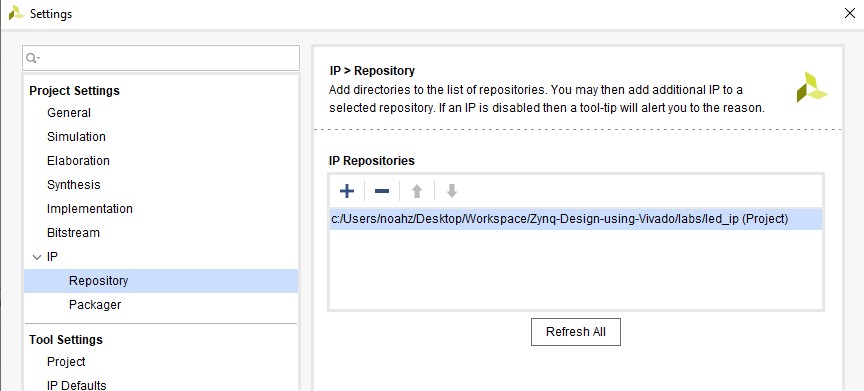
Specify IP Repository
- Click OK, Click Apply, and Click OK.
Add the Custom IP, BRAM, and the Constraints
- Click Open Block Design under IP Integrator in the Flow Navigator pane
- Right Click on the Diagram window and Add IP... Search for led_ip_v1.0 in the catalog by typing “led” in the search field.
- Double-click led_ip_v1_0 to add the core to the design.
- Select the IP in the block diagram and change the instance name to led_ip in the properties view.
- Double click the block to open the configuration properties
- For the PYNQ-Z2, set the width to 4.
- Click OK.
- Click on Run Connection Automation, select /led_ip/S_AXI and click OK to automatically make the connection from the AXI Interconnect to the IP.
-
Select the LED port on the led_ip instance (by clicking on its pin), right-click and select Make External. Rename the port as LED.
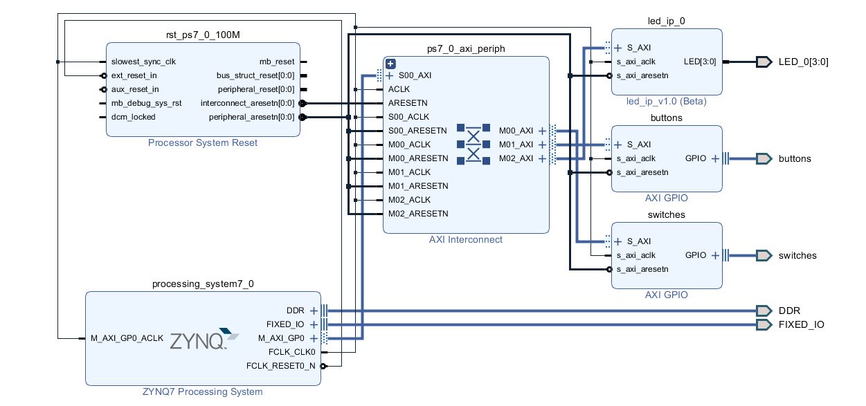
LED external port added and connected
-
Select the Address Editor tab and verify that an address has been assigned to led_ip.
- In the Block Diagram, Right click and select the Add IP option. Search for BRAM and add one instance of the AXI BRAM Controller
- Run Connection Automation on axi_bram_ctrl_0/S_AXI and click OK when prompted to connect it to the M_AXI_GP0 Master.
- Double click on the block to customize it and change the number of BRAM interfaces to 1 and click OK. Notice that the AXI Protocol being used is AXI4 instead of AXI4Lite since BRAM can provide higher bandwidth and the controller can support burst transactions.
- Click on Run Connection Automation to add and connect a Block Memory Generator by selecting axi_bram_ctrl_0/BRAM_PORTA and click OK (This could be added manually)
- Validate the design (F6) to ensure there are no errors , and click the regenerate button to redraw the diagram. The design should look similar to the figure below.
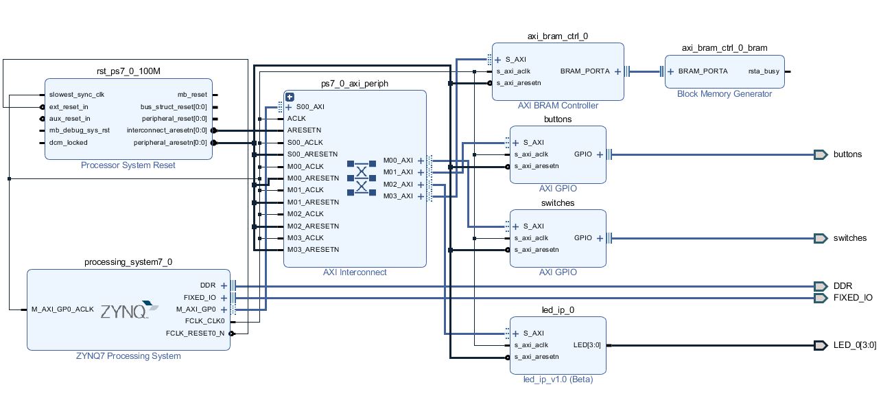
Completed Block Diagram
- In the Address editor, notice the Range of the axibramctrl_0 is 8K. We will leave it at that.
-
Press F6 to validate the design one last time.
- Click Add Sources in the Flow Navigator pane, select Add or Create Constraints, and click Next.
- Click the Blue Plus button, and then Add Files…, browse to the {sources}\lab3 folder, select lab3pynq_z2.xdc for _PYNQ-Z2.
- Click Finish to add the file.
- Expand Constraints folder in the Sources pane, and double click the *lab3_.xdc** file entry to see its content. This file contains the pin locations and IO standards for the LEDs on the Zynq board. This information can usually be found in the manufacturer’s datasheet for the board.
- Right click on system.bd and select Generate output products
- Click on Generate Bitstream and click Yes if prompted to save the Block Diagram, and click Yes again if prompted to launch Synthesis and Implementation. Click Cancel when prompted to Open the Implemented Design
Conclusion
Vivado IP packager was used to import a custom IP block into the IP library. The IP block was then added to the system. Connection automation was run where available to speed up the design of the system by allowing Vivado to automatically make connections between IP. An additional BRAM was added to the design. Finally, pin location constraints were added to the design. This lab is build upon and tested in Lab 4.