Writing Basic Software Application
Objectives
After completing this lab, you will be able to:
- Write a basic application to access an IP peripheral in Vitis IDE.
- Generate an ELF executable file.
- Download the bitstream and application and verify on a Zynq board.
Steps
Opening the Project
- Start the Vivado if necessary and open the lab3 project (lab3.xpr) you created in the previous lab.
-
Select File > Project > Save As… to open the Save Project As dialog box. Enter lab4 as the project name. Make sure that the Create Project Subdirectory and Include run results option is checked, the project directory path is {labs} and click OK.
This will create the lab4 directory and save the project and associated directory with lab4 name.
Export to Vitis and create Application Project
- Click File > Export > Export Hardware.
- Click on the checkbox of Include the bitstream and click Finish.
- Select Tools > Launch Vitis IDE and click OK.
- To tidy up the workspace and save unnecessary building of a project that is not being used, right click on the lab1_system and lab2_system projects from the previous lab, and click Close System Project, as these projects will not be used in this lab. They can be reopened later if needed.
- Select File > New > Application Project. Click Next to skip the welcome page if necessary.
- In the Platform Selection window, select Create a new platform from hardware (XSA) and browse to select the {labs}\lab4\system_wrapper.xsa file exported before.
- Enter lab4platform** as the _Platform name, click **Next.
- Enter lab4 as the Project Name. Click Next.
- Select the domain with name standalone_ps7_*, click Next.
- Click Next, and select Empty Application(C) and click Finish.
- Expand lab4 in the project view and right-click in the src folder and select Import Sources….
- Browse to select the sources\lab4 folder, click Open Folder.
- Select lab4.c and click Finish to add the file to the project. (Ignore any errors for now).
- Open lab4_platform > platform.spr from the Explorer.
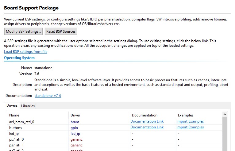
- Click Board Support Package under standalone_ps7_cortexa9_0.
-
Click on Documentation link corresponding to buttons peripheral under the Peripheral Drivers section to open the documentation in a default browser window. As our led_ip is very similar to GPIO, we look at the mentioned documentation.

Accessing device driver documentation
- View the various C and Header files associated with the GPIO by clicking Files at the top of the page.
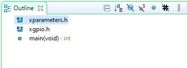
- Double-click on lab4.c in the Project Explorer view to open the file. This will populate the Outline tab.
-
Double click on xgpio.h in the Outline view on the right of the screen and review the contents of the file to see the available function calls for the GPIO.

Outline View
The following steps must be performed in your software application to enable reading from the GPIO: 1) Initialize the GPIO, 2) Set data direction, and 3) Read the data
Find the descriptions for the following functions:
XGpio_Initialize(XGpio *InstancePtr, u16 DeviceId) InstancePtr is a pointer to an XGpio instance. The memory the pointer references must be pre-allocated by the caller. Further calls to manipulate the component through the XGpio API must be made with this pointer.
DeviceId is the unique id of the device controlled by this XGpio component. Passing in a device id associates the generic XGpio instance to a specific device, as chosen by the caller or application developer.
XGpio_SetDataDirection(XGpio *InstancePtr, unsigned Channel, u32 DirectionMask)
InstancePtr is a pointer to the XGpio instance to be worked on.
Channel contains the channel of the GPIO (1 or 2) to operate on.
DirectionMask is a bitmask specifying which bits are inputs and which are outputs. Bits set to 0 are output and bits set to 1 are input.
XGpio_DiscreteRead(XGpio *InstancePtr, unsigned channel)
InstancePtr is a pointer to the XGpio instance to be worked on.
Channel contains the channel of the GPIO (1 or 2) to operate on
-
Open the header file xparameters.h by double-clicking on xparameters.h in the Outline tab
The xparameters.h file contains the address map for peripherals in the system. This file is generated from the hardware platform description from Vivado. Find the following #define used to identify the switches peripheral:
#define XPAR_SWITCHES_DEVICE_ID 1Note the number might be different.
Notice the other #define XPAR_SWITCHES* statements in this section for the switches peripheral, and in particular the address of the peripheral defined by XPAR_SWITCHES_BASEADDR
- Modify line 14 of lab4.c to use this macro (#define) in the XGpio_Initialize function.
- Do the same for the BUTTONS; find the macro (#define) for the BUTTONS peripheral in xparameters.h, and modify line 17 in lab4.c, and save the file.
Macro refers a to “pattern” that shows how a certain input should be mapped to an output. The macros here are defined in the xparameters.h file (which you should take a look at). ```C 14 XGpio_Initialize(&dip, XPAR_SWITCHES_DEVICE_ID); // Modify this 15 XGpio_SetDataDirection(&dip, 1, 0xffffffff); 16 17 XGpio_Initialize(&push, XPAR_BUTTONS_DEVICE_ID); // Modify this 18 XGpio_SetDataDirection(&push, 1, 0xffffffff);
```
- Build the project.
If there are any errors, check and fix your code. Your C code will eventually read the value of the switches and output it to the led_ip.
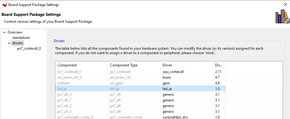
- Open lab4_platform > platform.spr from Explorer and click Board Support Package under standalone_ps7*, click on Modify BSP Settings.
- Select drivers on the left (under Overview)
-
If the led_ip driver has not already been selected, select Generic under the Driver column for led_ip to access the dropdown menu. From the dropdown menu, select led_ip, and click OK.

Assign led_ip driver
Examine the Driver code
The driver code was generated automatically when the IP template was created. The driver includes higher level functions which can be called from the user application. The driver will implement the low level functionality used to control your peripheral.
- In windows explorer, browse to led_ip\ip_repo\led_ip_1.0\drivers\led_ip_v1_0\src Notice the files in this directory and open led_ip.c. This file only includes the header file for the IP.
-
Close led_ip.c and open the header file led_ip.h and notice the macros:
LED_IP_mWriteReg( … )
LED_IP_mReadReg( … )
e.g: search for the macro name LED_IP_mWriteReg:
/**
    *
    * Write a value to a LED_IP register. A 32 bit write is performed.
    * If the component is implemented in a smaller width, only the least
    * significant data is written.
    *
    * @param   BaseAddress is the base address of the LED_IP device.
    * @param   RegOffset is the register offset from the base to write to.
    * @param   Data is the data written to the register.
    *
    * @return  None.
    *
    * @note
    * C-style signature:
    * 	void LED_IP_mWriteReg(Xuint32 BaseAddress, unsigned RegOffset,    Xuint32 Data)
    *
    */
#define LED_IP_mWriteReg(BaseAddress, RegOffset, Data) \
        Xil_Out32((BaseAddress) + (RegOffset), (Xuint32)(Data))
For this driver, you can see the macros are aliases to the lower level functions Xil_Out32( ) and Xil_Out32( ). The macros in this file make up the higher level API of the led_ip driver. If you are writing your own driver for your own IP, you will need to use low level functions like these to read and write from your IP as required. The low level hardware access functions are wrapped in your driver making it easier to use your IP in an Application project.
-
Modify your C code (see figure below, or you can find modified code in lab4_sol.c from the sources\lab4 folder) to echo the dip switch settings on the LEDs by using the led_ip driver API macros, and save the application.
-
Include the header file:
#include "led_ip.h" - Include the function to write to the IP (insert before the for loop):
LED_IP_mWriteReg(XPAR_LED_IP_S_AXI_BASEADDR, 0, dip_check);Remember that the hardware address for a peripheral (e.g. the macro XAR_LED_IP_S_AXI_BASEADDR in the line above) can be found in xparameters.h
#include "xparameters.h" #include "xgpio.h" #include "led_ip.h" //==================================================== int main (void) { XGpio dip, push; int i, psb_check, dip_check; xil_printf("-- Start of the Program --\r\n"); XGpio_Initialize(&dip, XPAR_SWITCHES_DEVICE_ID); // Modify this XGpio_SetDataDirection(&dip, 1, 0xffffffff); XGpio_Initialize(&push, XPAR_BUTTONS_DEVICE_ID); // Modify this XGpio_SetDataDirection(&push, 1, 0xffffffff); while (1) { psb_check = XGpio_DiscreteRead(&push, 1); xil_printf("Push Buttons Status %x\r\n", psb_check); dip_check = XGpio_DiscreteRead(&dip, 1); xil_printf("DIP Switch Status %x\r\n", dip_check); // output dip switches value on LED_ip device LED_IP_mWriteReg(XPAR_LED_IP_S_AXI_BASEADDR, 0, dip_check); for (i=0; i<9999999; i++); } } - Save the file and build the project.
Verify in Hardware
- Make sure that micro-USB cable(s) is(are) connected between the board and the PC. Change the boot mode to JTAG. Turn ON the power of the board.
- Open the Vitis Serial Terminal and add a connection to the corresponding port.
-
Right-click lab4_system > lab4 and select Launch Hardware (Single Application Debug).
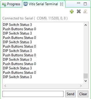
- Click Run. You should see the following output on the Terminal tab.

Connect to serial port
Note: Setting the DIP switches and push buttons will change the results displayed.
- Exit Vitis and Vivado.
- Power OFF the board.
Conclusion
Use Vitis IDE to define, develop, and integrate the software components of the embedded system. You can define a device driver interface for each of the peripherals and the processor. Vitis imports an XSA file, creates a corresponding MSS file and lets you update the settings so you can develop the software side of the processor system. You can then develop and compile peripheral-specific functional software and generate the executable file from the compiled object code and libraries.