Debugging Using Hardware Analyzer
Objectives
After completing this lab, you will be able to:
- Add a VIO core in the design
- Use a VIO core to inject stimulus to the design and monitor the response
- Mark nets as debug so AXI transactions can be monitored
- Add an ILA core in Vivado
- Perform hardware debugging using the hardware analyzer
- Perform software debugging using the Vitis IDE
Steps
Open the Project
- Start Vivado if necessary and open the lab2 project (lab2.xpr) you created in the previous lab
- Select File > Project > Save As … to open the Save Project As dialog box. Enter lab6 as the project name. Make sure that the Create Project Subdirectory option is checked, the project directory path is {labs} and click OK.
- Click Settings in the Flow Navigator pane.
- Expand IP in the left pane of the Project Settings form and select Repository.
- Click on the plus button of the IP Repositories panel, browse to {sources}\lab6\math_ip and click Select.
The directory will be scanned and one IP will be detected and reported.
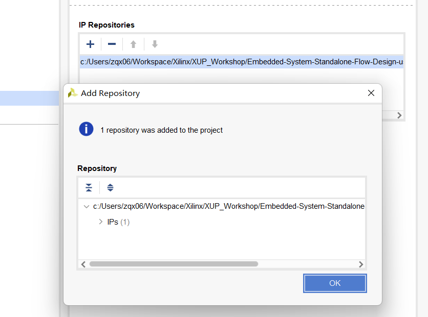
Specify IP Repository
- Click OK twice to close the window.
Add GPIO Instance for LEDs
- Click Open Block Design in the Flow Navigator pane to open the block diagram.
- Add an AXI GPIO IP by right clicking on the Diagram window > Add IP and search for AXI GPIO in the catalog, rename it to leds.
- Double click on the leds block, and select leds 4bits for the GPIO interface and click OK.
- Click Run Connection Automation, and select leds (which will include GPIO and S_AXI). Click on GPIO and S_AXI to check the default connections for these interfaces.
-
Click OK to automatically connect the S_AXI interface to the Zynq GP0 port (through the AXI interconnect block), and the GPIO port to an external interface. Rename the port leds_4bits to leds.
At this stage the design should look like as shown below.
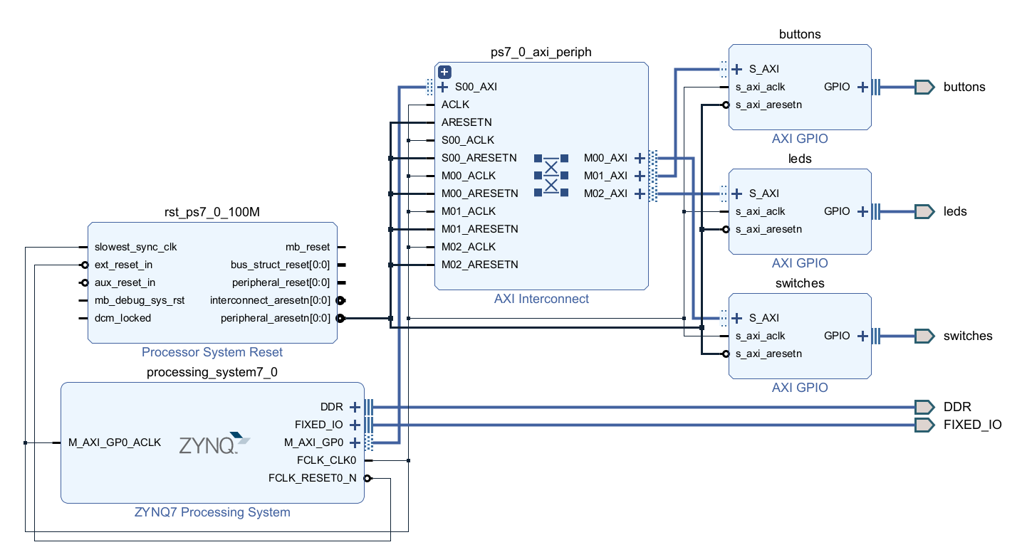
Block Design After add LED
Add the Custom IP
- Open the block diagram.
- Click the Plus button or right click the Diagram window and select Add IP, search for math in the catalog.
- Double-click the math_ip_v1_0 to add an instance of the core to the design.
-
Click on Run Connection Automation, ensure math_ip_0 and S_AXI are selected, and click OK.
The Math IP consists of a hierarchical design with the lower-level module performing the addition. The higher-level module includes the two slave registers.
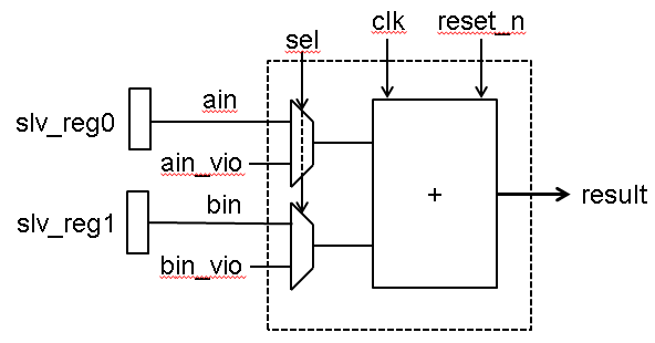
Custom Core's Main Functional Block
Add the ILA and VIO Cores
We want to connect the ILA core to the LED interface. Vivado prohibits connecting ILA cores to interfaces. In order to monitor the LED output signals, we need to convert the LED interface to simple output port.
Disable LEDs interface.
- Double-click the leds instance to open its configuration form.
- Click Clear Board Parameters and click OK to close the configuration form.
- Select leds port and delete it.
- Expand the gpio interface of the leds instance to see the associate ports.
Make the gpio_io_o port of the leds instance external and rename it as leds.
- Move the mouse close to the end of the gpio_io_o port, left-click to select (do not select the main GPIO port), and then right click and select Make External.
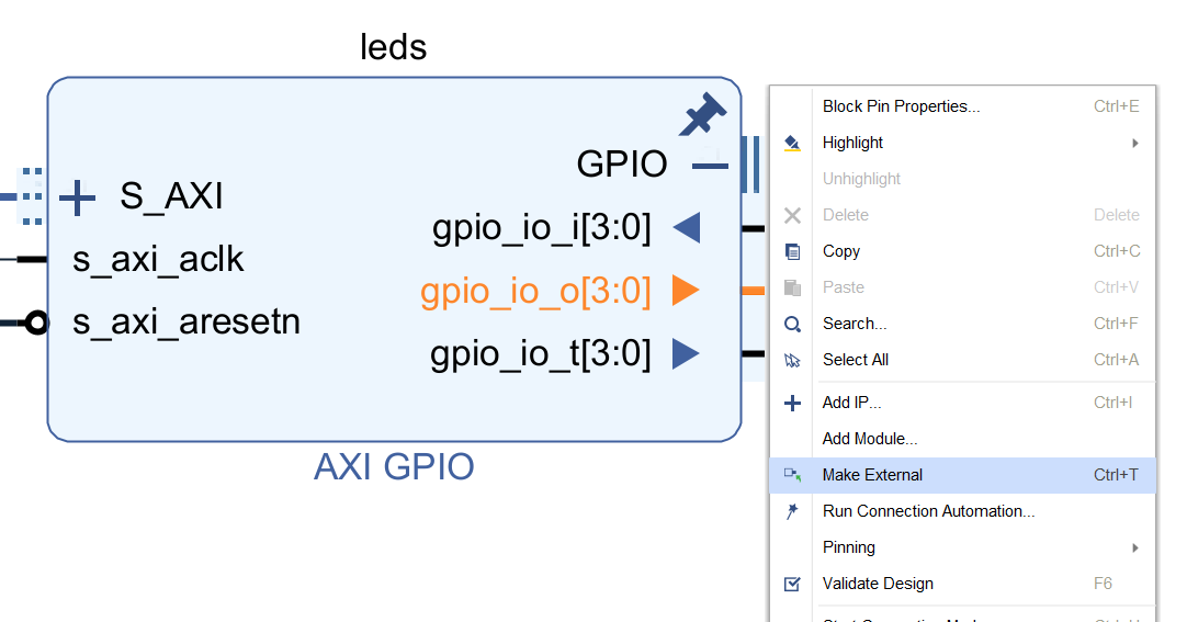
Make the gpio_io_o port External
The port connector named gpio_io_o will be created and connected to the port.
- Select the port gpio_io_o and change its name to leds by typing it in the properties form.
Enable cross triggering between the PL and PS
- Double click on the Zynq block to open the configuration properties.
- Click on PS-PL Configuration, and enable the PS-PL Cross Trigger interface.
- Expand PS-PL Cross Trigger interface > Input Cross Trigger, and select CPU0 DBG REQ for Cross Trigger Input 0.
- Similarly, expand Output Cross Trigger, and select CPU0 DBG ACK for Cross Trigger Output 0 and click OK.
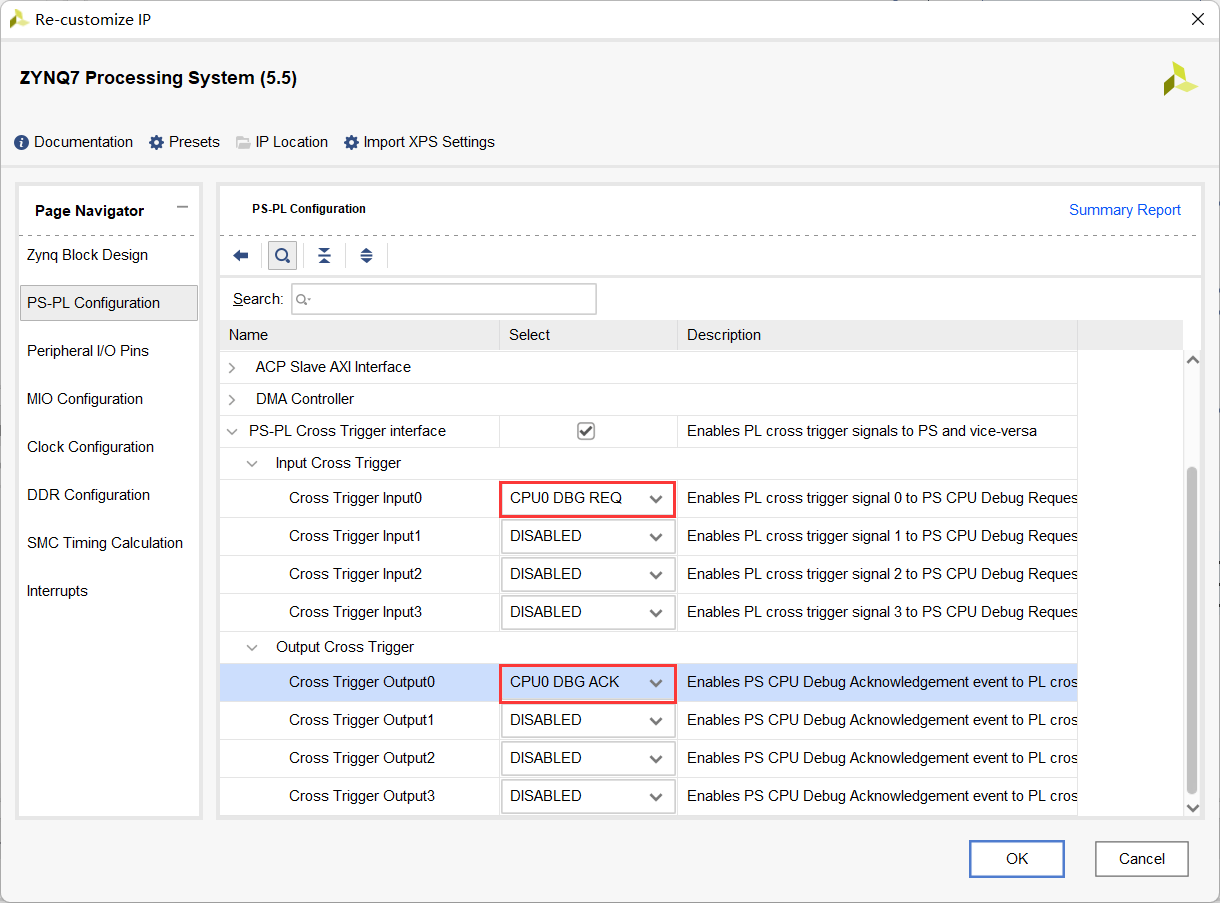
Enabling cross triggering in the Zynq processing system
Add the ILA core and connect it to the LED output port.
- Click the Plus button or right click the Diagram window and select Add IP, search for ila in the catalog.
- Double-click on the ILA (Integrated Logic Analyzer) to add an instance of it. The ila_0 instance will be added.
- Double-click on the ila_0 instance.
- Select Native as the Monitor type.
- Enable Trigger Out Port, and Trigger In port.
- Select the Probe Ports tab, and set the Probe Width of PROBE0 to 4 and click OK.
- Using the drawing tool, connect the probe0 port of the ila_0 instance to the gpio_io_o port of the leds instance.
- Connect the clk port of the ila_0 instance to the FCLK_CLK0 port of the Zynq subsystem.
- Connect TRIGG_IN of the ILA to TRIGGER_OUT_0 of the Zynq processing system, and TRIG_OUT of the ILA to the TRIGGER_IN_0.
Add the VIO core and connect it to the math_ip ports.
- Click the Plus button or right click the Diagram window and select Add IP, search for vio in the catalog.
- Double-click on the VIO (Virtual Input/Output) to add an instance of it.
- Double-click on the vio_0 instance to open the configuration form.
- In the General Options tab, leave the Input Probe Count set to 1 and set the Output Probe Count to 3
- Select the PROBE_IN Ports tab and set the PROBE_IN0 width to 9.
- Select the PROBE_OUT Ports tab and set PROBE_OUT0 width to 1 , PROBE_OUT1 width to 8 , and PROBE_OUT2 width to 8.
- Click OK.
- Connect the VIO ports to the math instance ports as follows:
probe_in -> result probe_out0 -> sel probe_out1 -> ain_vio probe_out2 -> bin_vio - Connect the CLK port of the vio_0 to FCLK_CKL0 net.
- The block diagram should look similar to shown below.
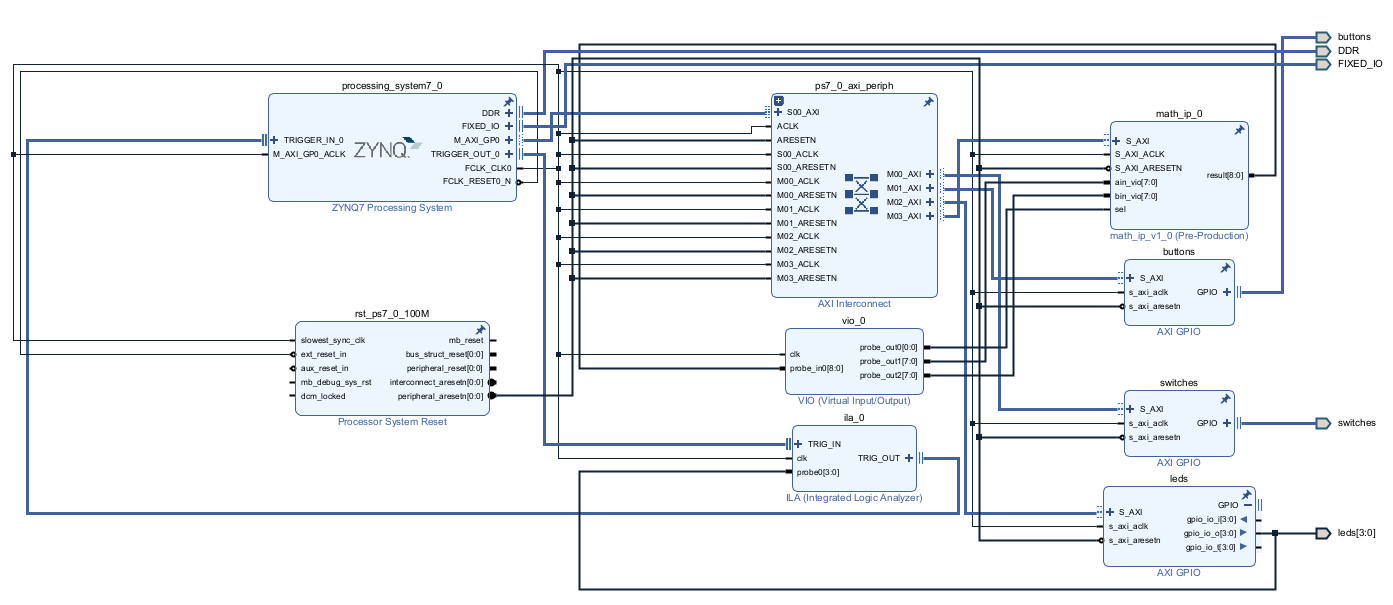
VIO added and connections made
Mark Debug the S_AXI connection between the AXI Interconnect and math_0 instance. Validate the design.
- Select the S_AXI connection between the AXI Interconnect and the math_ip_0 instance .
-
Right-click and select Debug to monitor the AXI4Lite transactions.
Notice that a system_ila IP instance got added and the M03_AXI <-> S_AXI connection is connected to its SLOT_0_AXI interface.
- Click the Run Connection Automation link to see the form where you can select the desired channels to monitor.
-
Change AXI Read Address and AXI Read Data channels to Data since we will not trigger any signals of those channels.
This saves resources being used by the design.
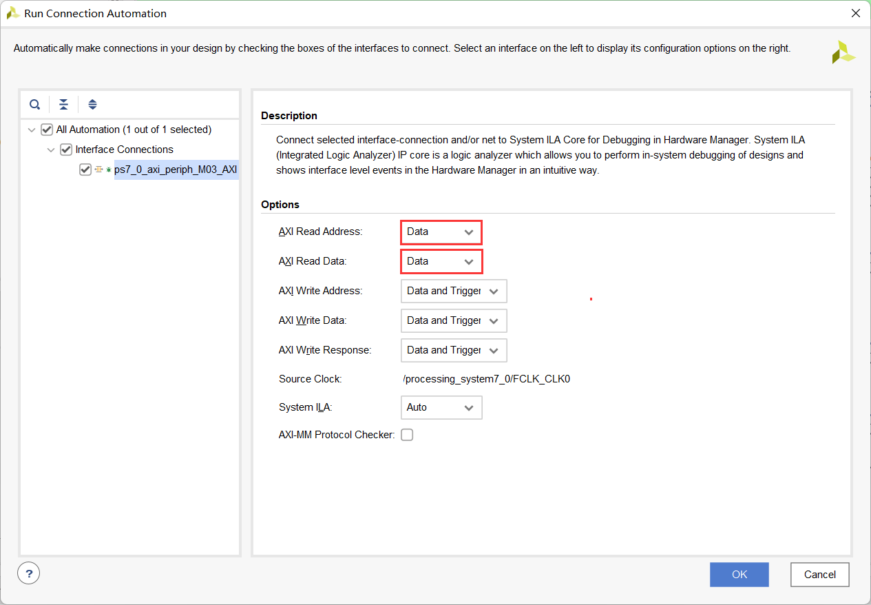
Selecting channels for debugging
- Verify that there are no unmapped addresses shown in the Address Editor tab.
-
Run Design Validation (Tools -> Validate Design) and verify there are no errors.
The design should now look similar to the diagram below
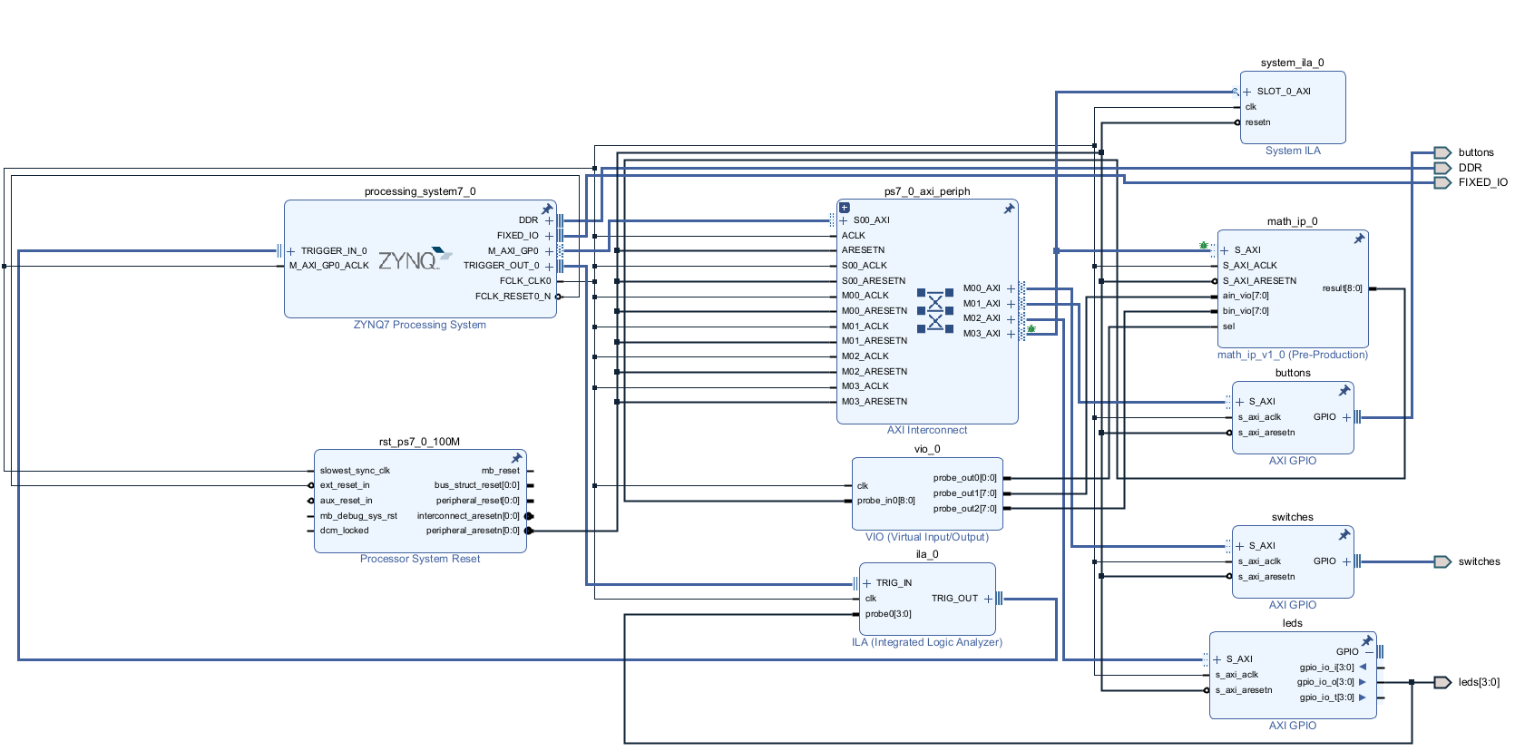
Completed Design
Add Design Constraints and Generate Bitstream
- Right click in the Sources panel, and select Add Sources.
- Select Add or Create Constraints and click Next.
- Click the Plus button then Add Files, browse to {sources}\lab6 and select lab6_pynz2.xdc.
- Click OK and then click Finish.
- Click on the Generate Bitstream to run the implementation and bit generation processes.
- Click Save to save the project (if prompted), OK to ignore the warning (if prompted), and Yes to launch Implementation (if prompted). Click OK to launch the runs.
- When the bitstream generation process has completed successfully, click Cancel.
Generate an Application in Vitis IDE
Export the implemented design and launch Vitis IDE.
- Export the hardware configuration by clicking File > Export > Export Hardware… , click the box to Include Bitstream
- Click OK to export and Yes to overwrite the previous project created by lab2.
- Launch Vitis IDE by clicking Tools > Launch Vitis IDE and click OK.
- Right-click on any opened system projects, and click Close System Project.
Create an empty application project named lab6, and import the provided lab6.c file.
- From the File menu select File > New > Application Project. Click Next to skip the welcome page if necessary.
- In the Platform Selection window, select Create a new platform from hardware (XSA) and browse to select the {labs}\lab6\system_wrapper.xsa file exported before.
- Enter lab6platform** as the _Platform name, click **Next.
- Name the project lab6, click Next.
- In the domain selection window, select standalone_ps7_cortexa9_0, click Next.
- In the templates selection window, select Empty Application(C), click Finish.
- Expand lab6 in the Explorer view, and right-click on the src folder, and select Import Sources….
- Browse to select the {sources}\lab6 folder, click Open Folder.
-
Select lab6.c and click Finish.
A snippet of the part of the source code is shown in the following figure. It shows that two operands are written to the custom core, the result is read, and printed out. The write transaction will be used as a trigger condition in the Vivado Logic Analyzer.
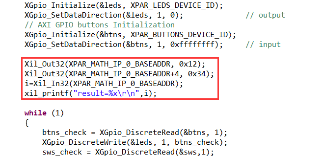
Source Code snippet
- Right click on lab6 from the Explorer View, and select Debug As > Debug Configurations
- Right click on Single Application Debug and select New Configuration to create a new configuration.
- In the Target Setup tab, check the Enable Cross-Triggering option, and click the Browse button.
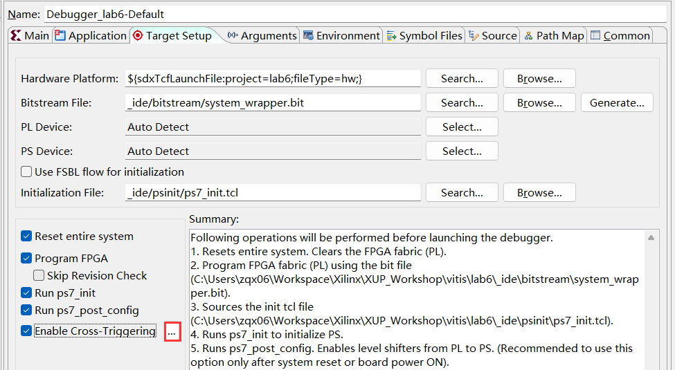
Enable cross triggering in the software environment
- When the Cross Trigger Breakpoints dialog box opens, click Create
- Select the options as shown below and click OK to set up the cross-trigger condition for Processor to Fabric.
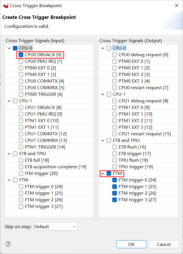
Enabling CPU0 for request from PL
- In the Cross Trigger Breakpoints dialog box click Create again.
- Select the options as shown below and click OK to set up the cross trigger condition for Fabric to Processor.
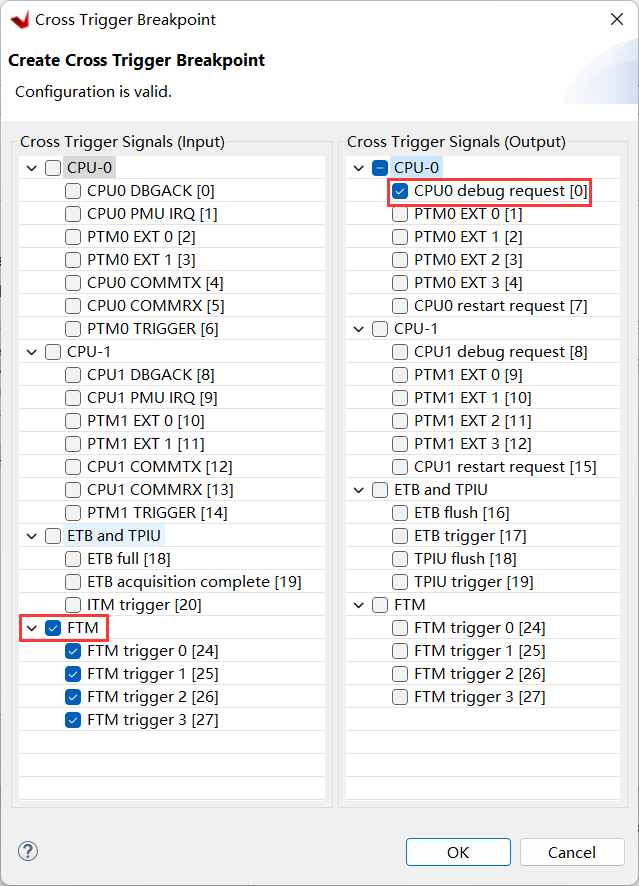
Enabling CPU0 for request to PL
- Click OK , then click Apply, then Close
- Build the project either by clicking the Hammer button or right-clicking on lab6 from Explorer View and selecting Build Project.
Test in Hardware
Start the debug session and establish serial communication.
- Connect and power up the board with JTAG mode.
- Select the lab6 project in Explorer View, right-click and select Debug As > Launch Hardware (Single Application Debug) to download the application. The program execution starts and suspends at the entry point.
- Click Window > Show View, search and open Vitis Serial Terminal.
- Click the Add button to connect to a port.
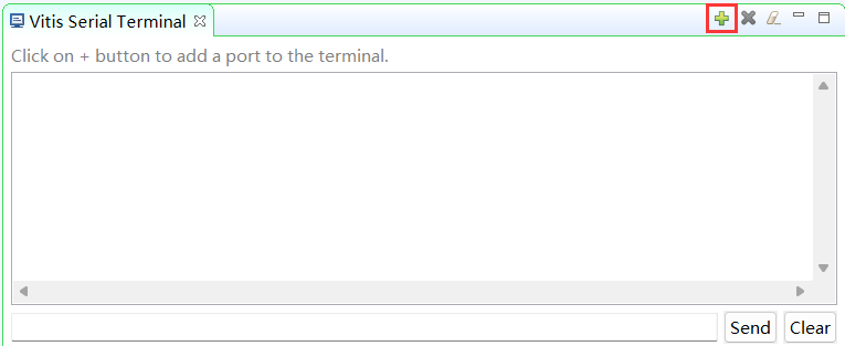
Add a Serial Port
- Select the Port from the dropdown menu. Keep the Advanced Settings as-is. Click OK.
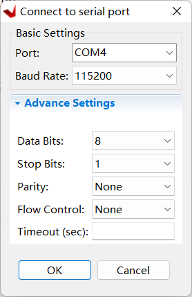
Connect to Serial Port
Start the hardware session from Vivado.
- Switch to Vivado.
- Click on Open Hardware Manager from the Flow Navigator pane to invoke the analyzer.
- Click on the Open Target > Auto connect to establish the connection with the board.
-
Select Window > Debug Probes
The hardware session will open showing the Debug Probes tab in the Console view.
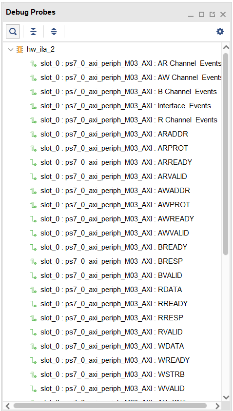
Debug probes
The hardware session status window also opens showing that the FPGA is programmed (we did it in Vitis IDE), there are three cores out of which the two ila cores are in the idle state.
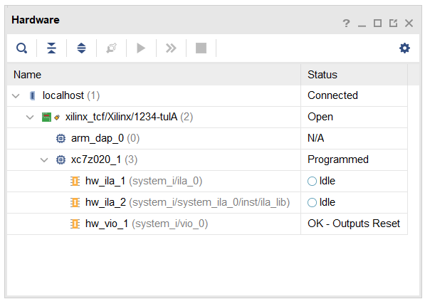
Hardware session status
- Select the XC7Z020, and click on the Run Trigger Immediate button to see the signals in the waveform window.
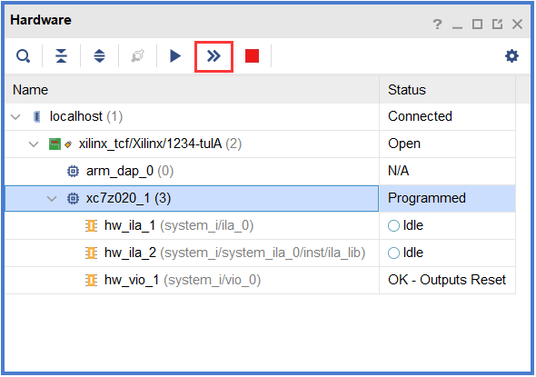
Opening the waveform window
Setup ILA Trigger Conditions for hw_ila_a
- Click on the hw_ila_2 tab to select it. In the Debug Probes window, under hw_ila_2, drag and drop the WDATA signal to the Trigger setup window.
- Set the value to XXXX_XX12 (HEX) (the value written to the math_0 instance at line 24 of the lab6.c).

Trigger Setup
- Similarly, add WREADY, WSTRB, and WVALID to the Trigger Setup window.
- Change the radix to [B](binary) for WSTRB, and change the value from XXXX to XXX1
- Change the value of WVALID and WREADY to 1.
- Set the trigger position of the hw_ila_2 to 512 in the window Settings – hw_ila_2
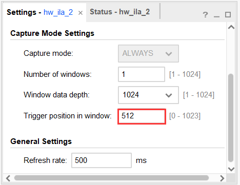
Setting up the ILA
- Similarly, set the trigger position in the Settings – hw_ila_1 window to 512.
- Select hw_ila_2 in the Hardware window and click on the Run Trigger button and observe that the hw_ila_2 core is armed and showing the status as Waiting For Trigger.
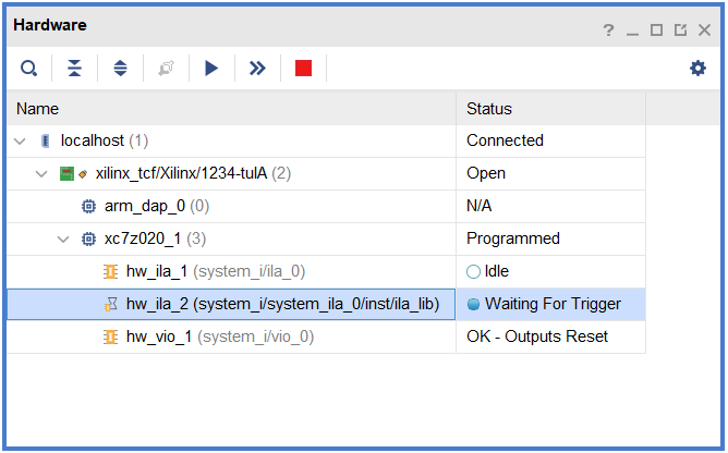
Hardware analyzer running and in capture mode
- Switch to Vitis IDE.
- Near line 27, double click on the left border on the line where xil_printf statement is defined in the lab6.c to set a breakpoint.

Setting a breakpoint
- Click on the Resume (F8) button to execute the program and stop at the breakpoint.
- Back to Vivado, notice that the hw_ila_2 status changed from Waiting for Trigger to Idle, and the waveform window shows the triggered output (select the hw_ila_data_2.wcfg tab if necessary).
- Move the cursor to closer to the trigger point and then click on the Zoom In button to zoom at the cursor. Click on the Zoom In button couple of times to see the activity near the trigger point. Similarly, you can see other activities by scrolling to right as needed.
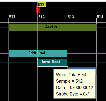
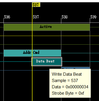
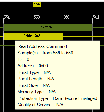
Zoomed waveform view of the three AXI transactions
Observe the following:
Around the 512th sample WDATA being written is 0x012 at offset 0 (AWADDR=0x0). At the 536th sample, offset is 0x4 (AWADDR), and the data being written is 0x034. At the 559th sample, data is being read from the IP at the offset 0x0 (ARADDR), and at 561th mark the result (0x46) is on the RDATA bus.
Interact with the VIO Cores in Vivado
- In Vivado, select the hw_vio_1 core in the Dashboard Options panel.
- Click on the Add button and select all vio signals to stimulate and monitoring. Change the vio_0_probe_out0 value to 1 so the math_ip core input can be controlled via the VIO core.
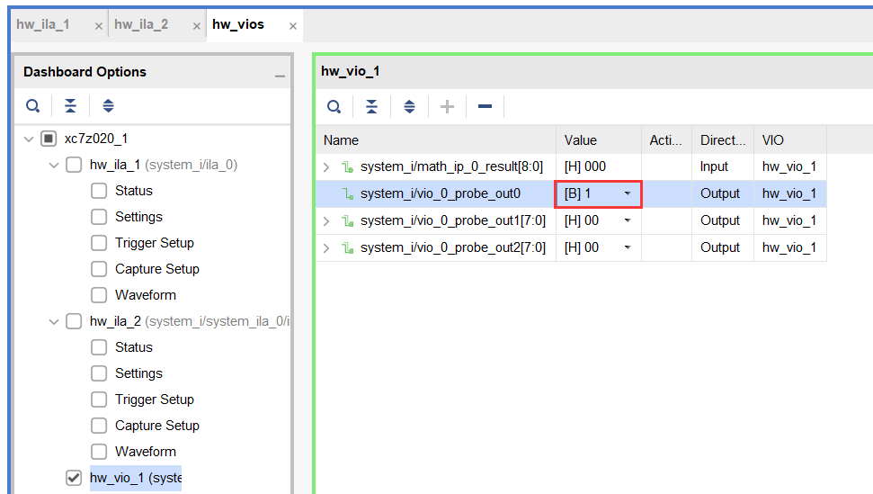
VIO probes
- Change vio_0_probe_out1 value to 55 (in Hex), and similarly, vio_0_probe_out2 value to 44 (in Hex). Notice that for a brief moment a blue-colored up-arrow will appear in the Activity column and the result value changes to 099 (in Hex).
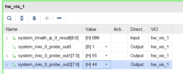
Input stimuli through the VIO core's probes
- Try a few other inputs and observe the outputs.
- Once done, set the vio_0_probe_out0 to 0 to isolate the vio interactions with the math_ip core.
Setup the ILA Trigger Conditions for hw_ila_1
- Select the hw_ila_1 in the Dashboard Options panel.
- Add the LEDs to the Trigger Setup, and set the trigger condition of the hw_ila_1 to trigger at LED output value equal to 0x5 for the PYNQ-Z2.

Setting up Trigger for hw_ila_1
-
Ensure that the trigger position for the hw_ila_1 is set to 512.
Make sure that the switches are not set to 11 on PYNQ-Z2 as this is the exit pattern.
-
Right-click on the hw_ila_1 in the hardware window, and arm the trigger by selecting Run Trigger. The hardware analyzer should be waiting for the trigger condition to occur.
- In the Vitis IDE Debug window, click on the Resume (F8) button.
- Press the push-buttons and see the corresponding LED turning ON and OFF.
- When the condition is met, the waveform will be displayed.

ILA waveform window after Trigger
Cross trigger a debug session between the hardware and software
- In Vivado, select hw_ila_1
- In the ILA properties window, expand the CONTROL, set the TRIGGER_MODE to BASIC_OR_TRIGG_IN , and the TRIG_OUT_MODE to TRIGGER_OR_TRIG_IN
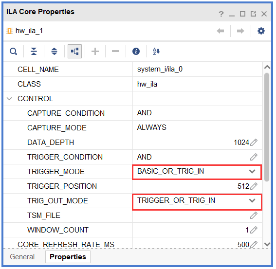
ILA Core Properties
-
In Vitis IDE, in the Design view, relaunch the software by right clicking on the lab6 project, and selecting Debug As > Launch Hardware (Single Application Debug). Click OK if prompted to relanuch.
The program will be loaded and the excution will suspend at the entry point
- Arm the hw_ila_1 trigger by clicking Run Trigger.
-
In Vitis IDE continue execution of the software to the next breakpoint (line 27).
When the next breakpoint is reached, return to Vivado and notice the ILA has triggered.
Trigger the ILA and cause the software to halt
- Click Step Over (F6) button twice to pass the current breakpoint
- Arm the hw_ila_1 trigger by clicking Run Trigger.
- Resume (F8) the software until it enters the while loop
- Press the push-buttons to 0x5, and notice that the application in Vitis IDE will break at some point (This point will be somewhere within the while loop)
- Click on the Resume button. The program will continue execution. Flip switches until it is 0x03.
- Click the Disconnect button in Vitis IDE to terminate the execution.
- Close the Vitis IDE by selecting File > Exit.
- In Vivado, close the hardware session by selecting File > Close Hardware Manager, and click OK.
- Close Vivado by selecting File > Exit.
- Turn OFF the power on the board.
Conclusion
In this lab, you added a custom core with extra ports so you can debug the design using the VIO core. You instantiated the ILA and the VIO cores into the design. You used Mark Debug feature of Vivado to debug the AXI transactions on the custom peripheral. You then opened the hardware session from Vivado, setup various cores, and verified the design and core functionality using Vitis IDE and the hardware analyzer.