Configuration and Booting
Objectives
After completing this lab, you will be able to:
- Create a bootable system capable of booting from the SD card.
- Create a bootable system capable of booting from the QSPI flash.
- Load the bitstream stored on the SD card or in the QSPI flash memory.
- Configure the PL section using the stored bitstream through the PCAP resource.
- Execute the corresponding application.
Steps
Create a Vivado Project
- Open Vivado and click Create New Project and click Next.
- Click the Browse button of the Project Location field of the New Project form, browse to {labs} , and click Select.
- Enter lab8 in the Project Name field. Make sure that the Create Project Subdirectory box is checked. Click Next.
- Select the RTL Project option and uncheck the Do not specify sources at this time option, click Next.
- Select Verilog as the Target Language in the Add Sources form, and click Next.
- Click Next to escape adding constraints.
- Search and select pynq-z2 board under board tag, click Next.
- Click Finish to create an empty Vivado project.
Creating the Hardware System Using IP Integrator
Create a block design to generate the ARM Cortex-A9 processor based hardware system.
- In the Flow Navigator, click Create Block Design under IP Integrator.
- Name the block system and click OK.
- Click the Add button or right clicking on the Diagram window > Add IP and search for zynq in the catalog.
- Double click on ZYNQ7 Processing System entry to add it to the design.
- Click on Run Block Automation in the message at the top of the Diagram panel. Leave the default option of Apply Board Preset checked, and click OK.
-
Double click on the Zynq block to open the Customization window.
A block diagram of the Zynq should now be open, showing various configurable blocks of the Processing System.
Configure the I/O Peripherals block to only have QSPI, UART 0, and SD 0 support.
- Click on MIO Configuration on the left.
- Expand the IO Peripherals on the right, uncheck ENET 0, USB 0, and GPIO > GPIO MIO, leaving UART 0 and SD 0 selected.
-
Click OK. The configuration form will close and the block diagram will be updated.
- Using wiring tool, connect FCLK_CLK0 to M_AXI_GP0_ACLK.
- Select the Diagram tab, and click on the Validate Design (F6) button to make sure that there are no errors.
Export the Design to Vitis IDE and create the software projects
Create the top-level HDL of the embedded system, and generate the bitstream.
- In Vivado, select the Sources tab, expand the Design Sources, right-click the system.bd and select Create HDL Wrapper and click OK.
- Click on Generate Bitstream and click Generate. Click Save to save the project, and Yes if prompted to run the processes. Click OK to launch the runs.
- When the bitstream generation process has completed successfully, click Cancel.
Export the design to Vitis IDE and create the Hello World application.
- Export the hardware configuration by clicking File > Export > Export Hardware….
- Click the box to Include Bitstream, then click OK.
- Launch Vitis IDE by clicking Tools > Launch VITIS IDE and click OK.
- In Vitis IDE, select File > New > Application Project.
- In the Platform window, click on the tag Create a new platform from hardware (XSA) and browse to select the exported .xsa file. Enter lab8platform** as the _Platform name. Click **Next.
- In the Application Project Details window, enter lab8helloworld** as the _Application project name. Click **Next.
- In the Domain window, leave the settings as defaults, and click Next.
- In the Templates window, select Hello World and click Finish.
- Expand lab8platform** in the _Explorer view, double-click on **platform.spr to open the platform project.
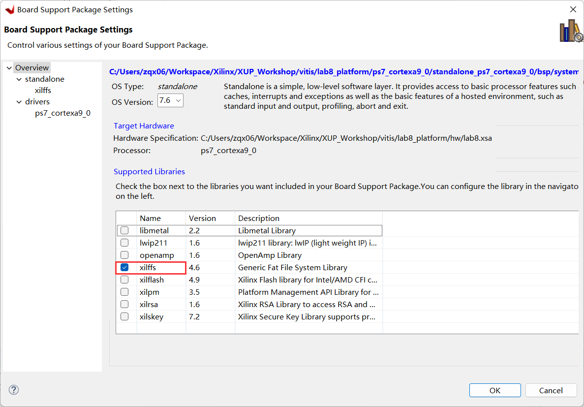
- On the left panel, click on Board Support Package, and click on Modify BSP Settings… on the right.
- Check the box to include xilffs and click OK.

Include xilffs in BSP
- Build the platform project. (Right-click on lab8platform** form the _Explorer view and select **Build Project or click on the hammer button).
- Build the system project. (Right-click on lab8helloworld_system** form the _Explorer view and select **Build Project or click on the hammer button).
Create a first stage bootloader (FSBL).
- Select File > New > Application Project.
- In the Platform window, click on the tag Select a platform from repository and select lab8_platform. Click Next.
- In the Application Project Details window, enter zynq_fsbl as the Application project name. Click Next.
- Click Next again.
- In the Templates window, select Zynq FSBL and click Finish.
-
Build the FSBL project by Right-clicking on zynq_fsbl_system form the Explorer view and select Build Project or clicking on the hammer button.
A zynq_fsbl project will be created which will be used in creating the BOOT.bin file. The BOOT.bin file will be stored on the SD card which will be used to boot the board.
Create the Boot Images and Test
Create the BOOT.bin file
- Using the System Explorer, create a directory under the {labs}\lab8 directory and name it image.
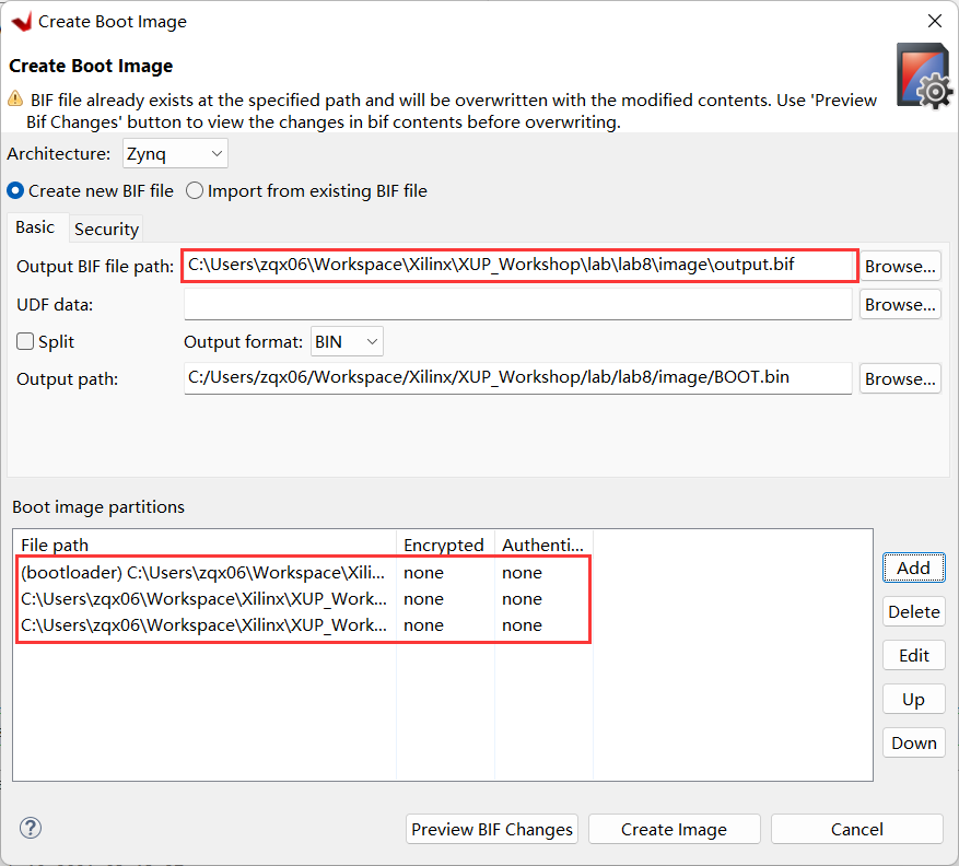
- In Vitis IDE, select Xilinx > Create Boot Image > Zynq and Zynq Ultrascale.
- Select Create new BIF file
- Click on the Browse button of the Output BIF file path field, browse to {labs}\lab8\image and click Save (leaving the default name of output.bif)
- Click on the Add button of the Boot image partitions, click the Browse button in the File path field, browse to {Vitis_Workspace}\zynq_fsbl\Debug directory (this is where the FSBL was created), select zynq_fsbl.elf and click Open.
- Make sure the partition type is bootloader, then click OK.

Adding FSBL partition
- Click on the Add button of the Boot image partitions and add the bitstream, system_wrapper.bit , from {Vitis_Workspace}\lab8_platform\hw and click OK.
- Click on the Add button of the Boot image partitions and add the software application, lab8_helloworld.elf , from {Vitis_Workspace}\lab8_helloworld\Debug and click OK.
-
Click the Create Image button.
The BOOT.bin and the output.bif files will be created in the {labs}\lab5\image directory. We will use the BOOT.bin for the SD card boot up.

Creating BOOT.bin image file
- Insert a blank MicroSD card (FAT32 formatted) in a Card reader, and copy the BOOT.bin file from the image folder into the MicroSD card.
Test the functionality by booting from SD card.
- Insert the MicroSD card into the board.
- Set the board to SD card boot mode and power ON the board.
- Connect your PC to the UART port with the provided micro-USB cable, and start Vitis Serial Terminal or other Terminal emulator programs setting it to the current COM port and 115200 baudrate.
- You should see the Hello World message in the terminal window. If you don't see it, then press the RST/SRST button on the board.
- Once satisfied, power OFF the board and remove the SD card.
Test the functionality by booting from QSPI flash.
- Set the board to JTAG mode and power ON the board.
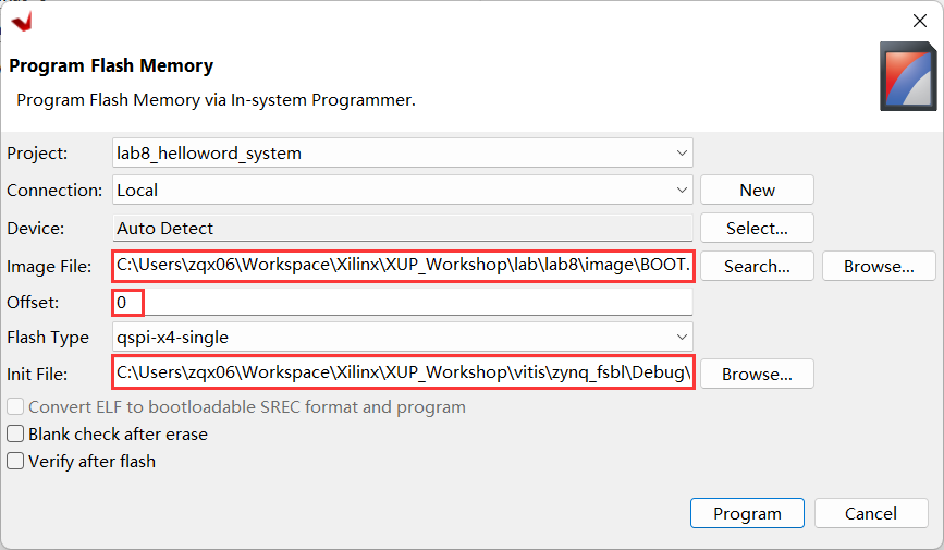
- Select Xilinx > Program Flash.
- Click the Browse button of the Image File field, browse to the {labs}\lab8\image directory, select BOOT.bin file, and click Open.
- Click the Browse button of the Init File field, browse to the {Vitis_Workspace}\zynq_fsbl\Debug directory, select zynq_fsbl.elf file, and click Open.
-
In the Offset field enter 0 as the offset and click the Program button.

Program Flash Memory form
- Power OFF the board, change the board to QSPI mode, and Power On the board
- Disconnect and reconnect the Terminal window.
- Press the RST\SRST to see the “Hello World” message in the terminal window.
- Once satisfied, power OFF the board.
Prepare for the Multi-Applications Boot Using SD Card
The lab1 and lab2 executable files are required in the .bin format before copying to the SD card. The area in memory allocated for each application need to be modified so that they do not overlap each other, or with the main application. The prepared bin files (lab1elf.bin and lab2elf.bin) provided in the directory: {sources}\lab8\SD_image can be used for copying to the SD card. Follow steps in Appendix A-1 and Appendix A-2 if you want to generate by yourself.
Create the lab8_sd application
- Select File > New > Application Project.
- In the Plarform window, click the tag Select a platform from repository and select lab8_platform
- Enter lab8_sd as the project name, click Next.
- Select standalone_ps7_cortexa9_0 as the domain. Click Next.
- Select Empty Application (C) in the Templates window and click Finish.
- Expand lab8_sd_system > lab8_sd in the project view and right-click in the src folder and select Import Sources…
- Browse to select the {sources}\lab8 folder, click Open Folder.
- Select lab8_sd.c, devcfg.c, devcfg,h, load_elf.s, click Finish to add these files to the project.
- Change, if necessary, LAB1_ELFBINFILE_LEN, LAB1_ELFBINFILE_LEN, LAB2_ELF_EXEC_ADDR, LAB2_ELF_EXEC_ADDR values and save the file.
- Build the project.
Create the SD Card Image and Test
Create the bin files from lab1 and lab2.
- Using the System Explorer, create directory called SD_image under the {labs}\lab8 directory.
-
In System Explorer, copy the system_wrapper.bit of the lab1 project into the SD_image directory and rename it lab1.bit, and do similar for lab2
{labs}/lab1/lab1.runs/impl_1/system_wrapper.bit -> SD_image/lab1.bit
{labs}/lab2/lab2.runs/impl_1/system_wrapper.bit -> SD_image/lab2.bit
The bootgen command of Vitis Shell will be used to convert the bit files into the required binary format. The bootgen requires a .bif file which has been provided in the sources/lab8 directory. The .bif file specifies the target .bit files.
- Open a command prompt by selecting Xilinx > Vitis Shell.
- In the command prompt window, change the directory to the bitstreams directory using cd command.
cd {labs}/lab8/SD_image - Generate the partial bitstream files in the BIN format using the provided “.bif” files located in the {sources} directory. Use the following command:
bootgen -image {sources}/lab8/lab1_bit_files.bif -w -process\_bitstream binbootgen -image {sources}/lab8/lab2_bit_files.bif -w -process\_bitstream bin - Rename the files lab1.bit.bin and lab2.bit.bin to lab1.bin and lab2.bin
-
The size of the file needs to match the size specified in the lab8_sd.c file. The size can be determined by checking the file's properties. If the sizes do not match, then make the necessary change to the source code and save it (The values are defined as LAB1_BITFILE_LEN and LAB2_BITFILE_LEN).

Checking the size of the generate bin file
Note that the lab1.bin and lab2.bin files should be the same size.
Create the BOOT.bin file
- In the SDK, select Xilinx > Create Boot Image > Zynq and Zynq Ultrascale.
- Select Create new BIF file.
- For the Output BIF file path, click on the Browse button and browse to {labs}\lab8\SD_image directory and click Save.
- Click on the Add button of the boot image partitions field and browse to {Vitis_Workspace}/lab8_platform/zynq_fsbl , select fsbl.elf , click Open , and click OK.
- Click on the Add button of the boot image partitions field and browse to {Vitis_Workspace}/lab8_platform/hw , select system_wrapper.bit , click Open , and click OK.
- Click on the Add button of the boot image partitions field and browse to {Vitis_Workspace}/lab8_sd/Debug , select lab8_sd.elf , click Open , and click OK.
-
Click the Create Image button.
The BOOT.bin file will be created in the {labs}lab8\SD_image directory.
Test the design functionality by booting from SD card
-
In Windows explorer, copy the lab1elf.bin and lab2elf.bin files either from the {sources}\lab8\SD_image directory or from the individual directories (if you did the optional parts in the previous step) and place them in the {labs}\lab8\SD_image directory.
{Vitis_Workspace}\lab1\Debug\lab1elf.bin -> SD_image
{Vitis_Workspace}\lab2\Debug\lab2elf.bin -> SD_image
- Insert a blank MicroSD card (FAT32 formatted) in an SD Card reader, and using the System Explorer, copy the two “.bin” files, the two “elf.bin” files, and BOOT.bin from the SD_image folder in to the SD card.
- Place the SD card in the board, and set the mode pins to boot the board from the SD card. Connect your PC to the UART port with the provided micro-USB cable.
- Power ON the board.
- Start the terminal emulator program and follow the menu. Press the RST/SRST button if you don't see the menu.
- When finished testing one application, either power cycle the board and verify the second application's functionality, or press the RST/SRST button on the board to display the menu again.
- When done, power OFF the board.
Create the QSPI application and image
The prepared bin files provided in the directory: {sources}\lab5\QSPI_image can be used for creating the MCS. Appendix B-1 and Appendix B-2 lists the steps of how to create such BIN files.
Create the lab8_qspi application
- Select File > New > Application Project.
- In the Plarform window, click the tag Select a platform from repository and select lab8_platform
- Enter lab8_qspi as the project name, click Next.
- Select standalone_ps7_cortexa9_0 as the domain. Click Next.
- Select Empty Application (C) in the Templates window and click Finish.
- Expand lab8_qspi_system > lab8_qspi in the project view and right-click in the src folder and select Import Sources…
- Browse to select the {sources}\lab8 folder, click Open Folder.
- Select lab8_qspi.c, click Finish to add it to the project.
- Build the project.
Create the lab8.mcs file
- Using the System Explorer, create the QSPI_image directory under the lab8 directory.
- Select Xilinx > Create Boot Image > Zynq and Zynq Ultrascale.
- Select Create new BIF file option, click the Browse button of the Output BIF file path field and browse to {labs}\lab8\QSPI_image directory, with default name output.bif, and click Save.
- Click on the Add button of the boot image partitions field and add the fsbl file, fsbl.elf , from {Vitis_Workspace}\lab8_platform\zynq_fsbl and click OK
- Click on the Add button of the boot image partitions field and add the bitstream file, system_wrapper.bit , from {Vitis_Workspace}\lab8_platform\hw and click OK
-
Click on the Add button of the boot image partitions field and add the lab8_qspi.elf file , from {Vitis_Workspace}\lab8_qspi\Debug and click OK
- Click on the Add button of the Boot image partition field again and add the lab1.bin , either from created boot image of the lab1 project (in {labs}\lab1) or from the provided {sources}\lab8\QSPI_image directory. Enter 0x400000 in the Offset field and click OK.
- Similarly, add the lab2.bin , either from the created boot image of the lab2 project (in {labs}\lab2) or from the provided {sources}\lab8\QSPI_image directory. Enter 0x800000 in the Offset field and click OK.
- Change the output filename to lab8.mcs and the location to lab8\QSPI_image.
- Click the Create Image button. The lab8.mcs file will be created in the lab8\QSPI_image directory.
Program the QSPI using the Flash Writer utility.
- Set the board in JTAG mode. Power ON the board.
- Select Xilinx > Program Flash.
- Click the Browse button of the Image File field, and browse to the {labs}\lab8\QSPI_image directory, select lab8.mcs file, and click Open.
A solution mcs file is provided in the {sources}\lab8\QSPI_image directory, use it if you have skipped the previous step of generate QSPI image.
- In the Offset field enter 0 as the offset and click the Program button. The QSPI flash will be programmed. It may take up to 4 minutes.
Test the QSPI Multi-Applications
- Power OFF the board and change it to QSPI mode, and power ON the board.
- Start the terminal emulator session and press RST/SRST button to see the menu.
-
Follow the menu and test the functionality of each lab.
Press 1 to load and execute lab2 or press 2 to load and execute lab2. Return to the menu by returning the board OFF and ON.
- Once satisfied, power OFF the board.
- Close Vitis IDE and Vivado
Conclusion
This lab led you through creating the boot images which can boot standalone applications from either the SD card or the QSPI flash memory. You then created the design capable of booting multiple applications and configurations which you developed in the previous labs.
Appendix A-1
Use objcopy command to convert the elf file of lab1 into the binary file
- Start the Vitis IDE and browse to the workspace pointing to lab1_system and click OK.
- Right-click on the lab1system > lab1** project, select the _Generate Linker Script option, change the code, data, heap, and stack sections to use the ps7_ddr_0, and click **Generate. Click Yes to overwrite the linker script.
- Expand the lab1_system > lab1 > src entry in the Explorer, and double-click on the lscript.ld to open it.
-
In the lscript editor view, change the Base Address of the ps7_ddr_0_AXI_BASEADDR from 0x00100000 to 0x00200000 , and the Size from 0x1FF00000 to 0x1FE00000.

Changing the Base address and the size
- Press Ctrl-S to save the change.
-
Build the system project.
- Select Xilinx > Vitis Shell to open the shell session.
- In the shell window, change the directory to {Vitis_Workspace}\lab1\Debug using the cd command.
- Convert the lab1.elf file to lab1elf.bin file by typing the following command.
arm-none-eabi-objcopy -O binary lab1.elf lab1elf.bin - Type
ls –lin the shell window and note the size of the file. In this case, it is 32776 , which is equivalent to 0x8008 bytes. - Determine the entry point “main()” of the program using the following command in the shell window.
arm-none-eabi-objdump -S lab1.elf | grep "<main>"It should be in the 0x0020074C.
Make a note of these two numbers (length and entry point) as they will be used in the lab8_sd application.
- Close the Shell window.
Appendix A-2
Use objcopy command to convert the elf file of lab2 into the binary file
- Start the Vitis IDE and browse to the workspace pointing to lab2_system and click OK.
- Right-click on the lab2system > lab2** project, select the _Generate Linker Script option, change the code, data, heap, and stack sections to use the ps7_ddr_0, and click **Generate. Click Yes to overwrite the linker script.
- Expand the lab2_system > lab2 > src entry in the Explorer, and double-click on the lscript.ld to open it.
-
In the lscript editor view, change the Base Address of the ps7_ddr_0_AXI_BASEADDR from 0x00100000 to 0x00600000 , and the Size from 0x1FF00000 to 0x1FA00000.

Changing the Base address and the size
- Press Ctrl-S to save the change.
-
Build the system project.
- Select Xilinx > Vitis Shell to open the shell session.
- In the shell window, change the directory to {Vitis_Workspace}\lab2\Debug using the cd command.
- Convert the lab2.elf file to lab2elf.bin file by typing the following command.
arm-none-eabi-objcopy -O binary lab2.elf lab2elf.bin - Type
ls –lin the shell window and note the size of the file. In this case, it is 32776 , which is equivalent to 0x8008 bytes. - Determine the entry point “main()” of the program using the following command in the shell window.
arm-none-eabi-objdump -S lab2.elf | grep "<main>"It should be in the 0x00600584.
Make a note of these two numbers (length and entry point) as they will be used in the lab8_sd application.
- Close the Shell window.
Appendix B-1
This step bring in MULTIBOOT register related code in Lab1. It then convert the lab1 executable file to the required (.bin) format.
- Start Vitis IDE and browse to the workspace pointing to lab1 and click OK.
- Right-click on the lab1 entry, select the C/C++ Build Settings option.
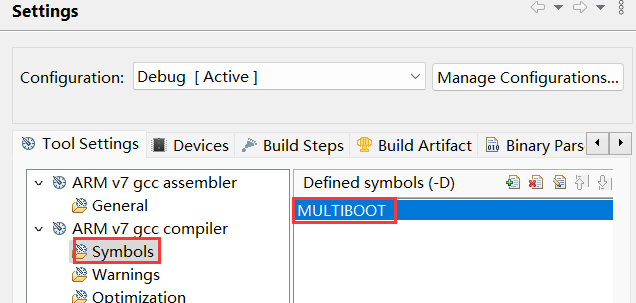
- Select Symbols in the left pane under the ARM gcc compiler group, click the + button on the right, enter MULTIBOOT in open form, click OK and click OK again.

Setting user-defined symbol
- Rebuild the system project.
- Select Xilinx > Create Boot Image > Zynq and Zynq Ultrascale.
- Select Create new BIF file option, click the Browse button of the Output BIF file path field and browse to {labs}\lab1 directory, set filename as lab1, and click Save.
- Add below three files in the Boot image partitions field
- {Vitis_Workspace}\lab8_platform\zynq_fsbl\fsbl.elf
- {Vitis_Workspace}\lab1_platform\hw\system_wrapper.bit
- {Vitis_Workspace}\lab1\Debug\lab1.elf
- Change the output filename to lab1.bin making sure that the output directory is {labs}\lab1.
- Click the Create Image button. The lab1.bin will be created in the lab1 directory.
Appendix B-2
This step bring in MULTIBOOT register related code in Lab2. It then convert the lab1 executable file to the required (.bin) format.
- Start Vitis IDE and browse to the workspace pointing to lab2 and click OK.
- Right-click on the lab2 entry, select the C/C++ Build Settings option.
- Select Symbols in the left pane under the ARM gcc compiler group, click the + button on the right, enter MULTIBOOT in open form, click OK and click OK again.
- Rebuild the system project.
- Select Xilinx > Create Boot Image > Zynq and Zynq Ultrascale.
- Select Create new BIF file option, click the Browse button of the Output BIF file path field and browse to {labs}\lab2 directory, set filename as lab2, and click Save.
- Add below three files in the Boot image partitions field
- {Vitis_Workspace}\lab8_platform\zynq_fsbl\fsbl.elf
- {Vitis_Workspace}\lab2_platform\hw\system_wrapper.bit
- {Vitis_Workspace}\lab2\Debug\lab2.elf
- Change the output filename to lab2.bin making sure that the output directory is {labs}\lab2.
- Click the Create Image button. The lab2.bin will be created in the lab2 directory.