Vivado FPGA Design Flow on Spartan and Zynq
This workshop will show how to develop digital designs for AMD FPGAs using the Vivado software suite. The following topics will be covered in this tutorial:
- Design synthesis
- Implementation
- I/O planning
- Simulation
- Static timing analysis
- Debug features of Vivado
The tutorial instructions target the following hardware and software:
GitHub repository
All the materials for this tutorial, including these webpages, are hosted on GitHub: https://github.com/xilinx/xup_fpga_vivado_flow. You can download a Zip, or git clone this repository to get a copy of the materials.
git clone https://github.com/xilinx/xup_fpga_vivado_flow
Lab Source Files
Source files for the labs: https://github.com/Xilinx/xup_fpga_vivado_flow/tree/main/source
Labs Overview:
Lab 1
This lab guides you through the process of using Vivado IDE to create a simple HDL design targeting the Boolean or PYNQ-Z2. You will simulate, synthesize, and implement the design with default settings. Finally, you will generate the bitstream and download it into the hardware to verify the design functionality.
Lab 2
This lab shows you the synthesis process and effect of changing of synthesis settings targeting the Boolean or PYNQ-Z2. You will analyze the design and the generated reports.
Lab 3
This lab continues from the previous lab. You will perform static timing analysis. You will implement the design with the default settings and generate a bitstream. Then you will open a hardware manager session and program the FPGA.
Lab 4
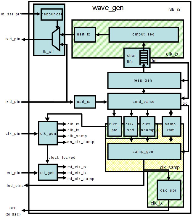
In this lab you will use the IP Catalog to generate a clock resource. You will instantiate the generated clock core in the provided waveform generator design. You will also use IP Integrator to generate a FIFO core and then use it in the HDL design.
Lab 5
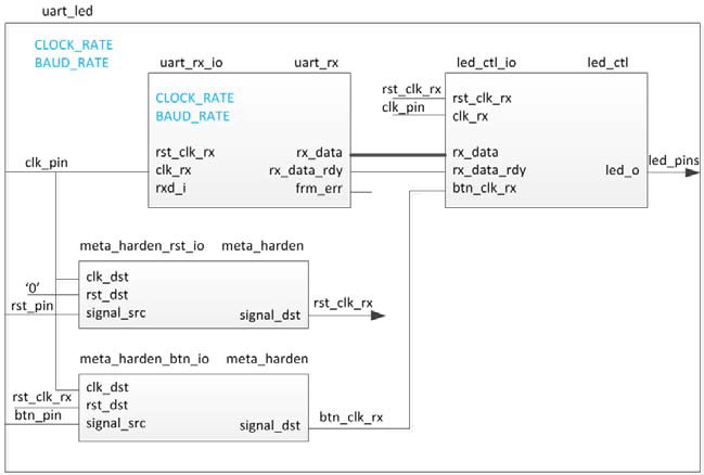
In this lab you will use the uart_led design that was introduced in the previous labs. You will start the project with I/O Planning type, enter pin locations, and export it to the rtl. You will then create the timing constraints and perform the timing analysis.
Lab 6
In this lab you will use the uart_led design that was introduced in the previous labs. You will use Mark Debug feature and also the available Integrated Logic Analyzer (ILA) core (in IP Catalog) to debug the hardware.
NOTE
Board support for the Boolean and PYNQ-Z2 are not included in Vivado 2021.2 by default.
For Pynq-z2:
When creating Vivado projects, targeting to the parts to specify the device, The Boolean uses a xc7z020clg400-1 Zynq-7 device with the following attributes:
| Part Number | xc7z020clg400-1 |
|---|---|
| Family | Zynq-7 |
| Package | clg400 |
| Speed Grade | -1 |
| Temperature Grade | C |
For Boolean:
When creating Vivado projects, targeting to the parts to specify the device, The Boolean uses a xc7s50csga342-1 Spartan-7 device with the following attributes:
| Part Number | xc7s50csga342-1 |
|---|---|
| Family | Spartan-7 |
| Package | ccsga324 |
| Speed Grade | -1 |
| Temperature Grade | C |
Hardware Setup
PYNQ-Z2: Connect the board to the PC using a micro USB cable. Make sure that a jumper is connected to JTAG (between JP1_1 and JP1_2) to use the board in the development mode. Also, make sure that another jumper is placed between J9_2 and J9_3 to select USB as a power source.
Boolean: Connect your Boolean board to your Computer with a micro USB cable. Make sure you connect the micro-USB cable to the port labeled “PROG UART”. Turn on your board by moving the switch in the top-left corner to the on position. You’ll see a Green LED by the switch when it powers on. If your board doesn’t power on, check that the blue jumper by the port labeled “EXTP” is set to “USB”.
Copyright© 2022 AMD-Xilinx