AVED Build Scripts
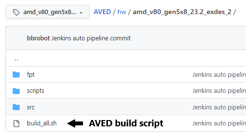
The AVED Git repository contains a shell script which can be used to build any of the AVED example designs. build_all.sh is the main build script, which calls other build scripts for each step of the build.
Example Build Command
The following command demonstrates how to build a V80 design.
$ cd <aved>/hw/amd_v80_gen5x8_23.2_exdes_2
$ ./build_all.sh
Build Steps
The build script divides the build flow into a number of separate steps.
hw - builds the hardware design into an XSA file
fw - using the XSA file, compiles the firmware into an elf file
fpt - creates the flash partition table as a binary file
pdi - uses the outputs of previous steps to generate the device programming files
hw step
The hw step of the build flow operates on the AVED hardware design described here: Hardware Design - V80. A /build directory is created, where the implemented hardware design and Vivado log are generated. The xpr file for this project is located here <aved>/hw/amd_v80_gen5x8_23.2_exdes_2/build/prj.xpr.
This Vivado project is used to generate the BD design, run Synthesis & Implementation, and create the initial PDI. The write_hw_platform command is run on the implemented design to create an XSA (named amd_v80_gen5x8_23.2_exdes_2.xsa), which is used as a hardware handoff file to the AMC build in the fw build step.
fw step
The fw step of the build flow operates on the AVED AMC firmware design described here: Firmware Design - AVED. The fw step builds the AMC firmware and generates a FPT binary.
The AMC build is run in the AMC source code directory (i.e., <aved>/fw/AMC) using the AMC’s own build script (<aved>/fw/AMC/scripts/build.sh).
The AMC’s build.sh can take a number of different build options (which are detailed in the AMC’s Profiles and CMake build process page), but the the AVED build flow executes it with these specific options.
# Command ./scripts/build.sh
#   -os freertos10_xilinx
#   -profile <board profile e.g. v80>
#   -xsa <absolute_path_to_xsa>
where the os is always freertos10_xilinx, the profile is the AMD Alveo™ card name and the xsa is the amd_v80_gen5x8_23.2_exdes_2.xsa generated in the hw step.
The resultant ELF file from the AMC build is then stored in the fw directory (<aved>/fw/AMC/build/amc.elf), and is then copied into the hardware build directory.
Tip: If the firmware has changed and the hardware design has not, the hardware XSA does not need to be re-built when compiling the firmware. The hw step can be commented out in the build script, which will reduce build time.
fpt step
Another important concept of the AVED design is the FPT (see AVED - Device Programming) as this defines how the flash memory is organized.
The contents of the FPT are defined in a JSON file in the AMC source code directory <aved>/fw/AMC/scripts/fpt.json, and another script (also in AMC source code directory - <aved>/fw/AMC/scripts/gen_fpt.py) is used to convert the JSON contents into a binary file.
The execution of the gen_fpt.py takes place during the fpt step, and the resultant binary file is stored in the fw directory (<aved>/fw/AMC/build/fpt.bin).
pdi step
The pdi step is responsible for combining outputs from previous steps in order to create two different PDI files. The two generated PDIs are known as the Design PDI and the FPT_Setup PDI.
design PDI: <aved>/hw/amd_v80_gen5x8_23.2_exdes_2/build/amd_v80_gen5x8_23.2_exdes_2_nofpt.pdi
FPT Setup: <aved>/hw/amd_v80_gen5x8_23.2_exdes_2/amd_v80_gen5x8_23.2_exdes_2.pdi
First, the Design PDI is created when bootgen is called to combine the PDI generated in the hw step with the AMC ELF which was generated in the fw step. This PDI contains the complete AVED design and is intended to be written to a flash partition over PCIe using AMI.
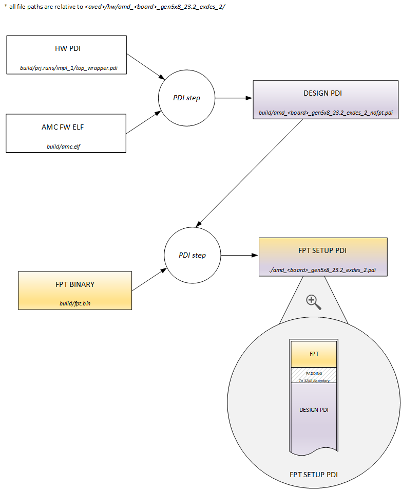
The FPT setup PDI is intended to be written to flash over JTAG using HW Manager. This PDI sets up the flash so that it can be used by AMC/AMI.
This basically means that it contains the FPT at the beginning of the memory, which AMI/AMC can then process to determine where in flash it can write different Design PDIs.
The FPT setup PDI is generated using the <aved>/hw/amd_v80_gen5x8_23.2_exdes_2/fpt/fpt_pdi_gen.py script. This script takes the previously generated Design PDI and appends the FPT Binary to the start of the file. Padding is added between the FPT and the design PDI to ensure that the design PDI is aligned to a 32KB boundary (this is a requirement of the PMC boot search).
Effectively, the FPT Setup PDI configures the flash to contain the FPT along with Design PDI in the 1st PDI Partition.
Writing FPT setup PDI to flash is only required if the FPT has been modified. Otherwise, if the FPT in flash is still valid, then the Design PDI can be written to one of the PDI partitions over PCIe using AMI.
Page Revision: v. 38