Internals of Hash-Semi-Join (Multi-Process-Unit Version)
This document describes the structure and execution of Hash-Semi-Join, implemented as hashSemiJoin function. Its implementation is based on Hash-Join-MPU.
Hash-Semi-Join returns rows from the outer table where a field of outer table matches with the one of inner table. Even if a record of outer table matches with many rows in inner table, the one of outer table is output only once.
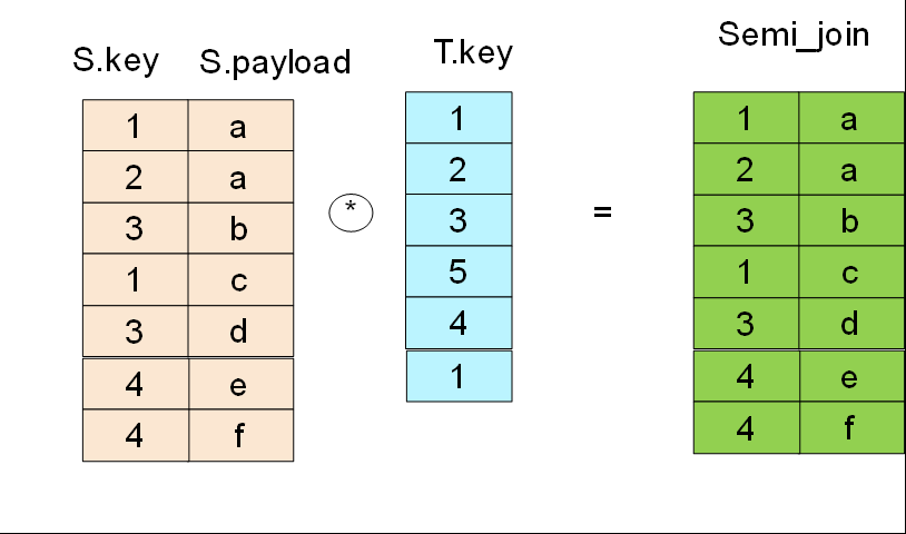
- Hash-Semi-Join is written using the EXISTS or IN constructs. For example:
- select * from S where S.key in ( select key from T )
Principle
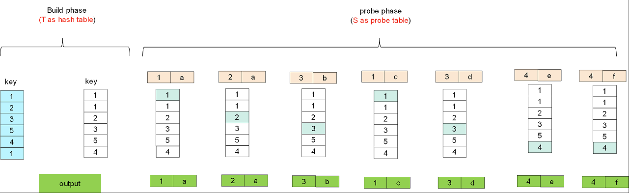
There are two stages in Hash-Semi-Join:
- build: the inner table is used for hash table for rapid searching matching rows.
- probe: the outer table is used for probe table. Each record of probe table is applied the same hash function on the joining column and will be hit the corresponding entry in the hash table. If a record of probe table first matches with a row in hash table, it will be output and never output again even if matches again.
Structure
The structure of Hash-Semi-Join is same as that of Hash-Join-MPU.
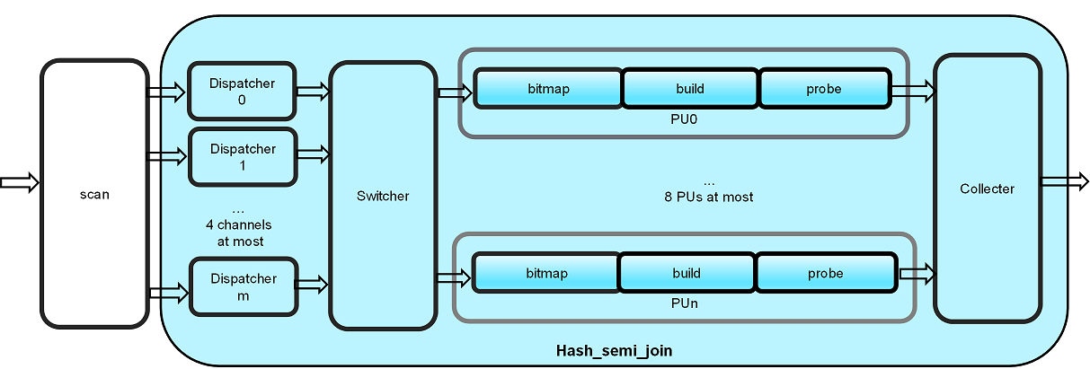
The Hash-Semi-Join primitive has a multi-PU design internally to utilize the advantage of high memory bandwidth in Xilinx FPGA. Workload is distributed based on MSBs of hash value of join key to Processing Units (PU’s), so that each PU can work independently. Current design use 8 PUs as default, and served by 4 input channels. The input of key and payload can be processed as a pair in each cycle.
There are several kind of modules in the design, and the detailed functionality of each module is described as below:
- scan: Outer table are input first and converted to steam twice continually, then inner table are input and converted to stream. Key and payload are pre-stored in DDR/HBM of FPGA which can be scanned as input streams here.
- Dispatcher: All records either in outer or inner table are input by one or more (only 1 , 2 or 4 is supported) channels after scan. Dispatcher computes each key’s hash value and choose the MSBs for dispatching, so that the input stream with same hash value are processed by the same PU. That is to say, the input stream will be divided into multiple PUs (only 1,2,4 or 8 is supported).
- Switcher: Switcher merges multi-channel output of dispatchers into one channel and distributes them to each PU according the MSB value of hash.
- Bitmap: Bitmap counts hash collisions and builds a bitmap(bit_vector).
- Build: The rows of key and payload in the same PU are mapped to the bitmap and stored in a buffer.
- Probe: The keys in inner table are matched with that in outer table.
- Collecter: Merges each PU’s output into one output stream.
The work stages of these modules are show in the following table:
| input | dispatcher | switcher | bitmap | build | probe | collecter |
| small/inner table | work | work | work | |||
| small/inner table | work | work | work | |||
| big/outer table | work | work | work | work |
The default number of PU is set to 8, as each PU requires a dedicated bank to avoid conflicts, and due to DDR/HBM memory access delay, 4 channels can serve enough data to these PU’s. Each PU performs Hash-Semi-Join in 3 phases.
- build bitmap: with inner table as input, the number of keys falls into each hash values are counted. The number of counts are stored in bit vector in URAM. After a full scan of the inner table, the bit vector is walked once, accumulating the counts to offsets of each hash.
- build unit: the inner table is read in again, and stored into DDR/HBM buffers of that PU. By referencing the bit vector in URAM created in previous phase, the kernel knows where to find empty slots for each key, and once a inner table payload and key is written into DDR/URAM, the offset in bit vector is increased by 1, so that the next key of same hash value can be written into a different place. As the number of keys with each hash have been counted, such offset increase won’t step into another key’s slot.
- probe unit: finally, the outer table is read in, and again by referencing the bit vector with hash of key, we can know the offset of this hash and number of keys with the same hash. Then the possible matched key and payload pairs can be retrieved from DDR/HBM, and joined with outer table payload after key comparison.
Important
To reduce the storage size of hash-table on FPGA-board, the inner table has to be scanned in TWICE, and followed by the outer table ONCE.
Caution
Currently, this primitive expects unique key in inner table.
This hashSemiJoinMPU primitive has only one port for key input and one port for payload input.
If your tables are joined by multiple key columns or has multiple columns as payload,
please use combineCol to merge the column streams, and
use splitCol to split the output to columns.
There are two versions of this primitive currently, with different number of slots for hash collision and key duplication. The version with more slots per hash entry has less total row capacity, as summarized below:
row capacity hash slots 2M 262144 (0.25M)