Using the Examples
Compiling and Simulating Using the Example Design
A Makefile is included with the example design. It is located inside the L2/examples/fir_129t_sym/ directory. Use the following steps to compile, simulate and verify the example design using the Makefile.
Clean Work directory and all output files
make clean
Compile the example design.
make compile
Simulate the example design.
make sim
This generates the file output.txt in the aiesimulator_output/data directory.
To compare the output results with the golden reference, extract samples from output.txt, then perform a diff with respect to the reference using the following command.
make check_op
Display the status summary with.
make get_status
This populates the status.txt file. Review this file to get the status.
Note
All of the preceding steps are performed in sequence using the following command:
make all
Using the Vitis Unified Software Platform to Run an Example Design
This section briefly describes how to create, build, and simulate a library element example using the Vitis™ integrated design environment (IDE).
Steps for Creating the Example Project in the Vitis IDE
Fir129Example_system is a pre-packaged Vitis project (in compressed format) that can be downloaded here: Fir129Example_system. This can be imported into the Vitis IDE in a few steps, as described below.
Set the environment variable DSPLIB_ROOT. This must be set to the path to your directory where DSPLib is installed.
setenv DSPLIB_ROOT <your-install-directory/dsplib>
Type vitis to launch the Vitis IDE, and create a new workspace.
Select File → Import → Vitis project exported zip file.
Click Next and browse to your download directory and select the downloaded ZIP file.
Set the correct path to the VCK190 platform file directory.
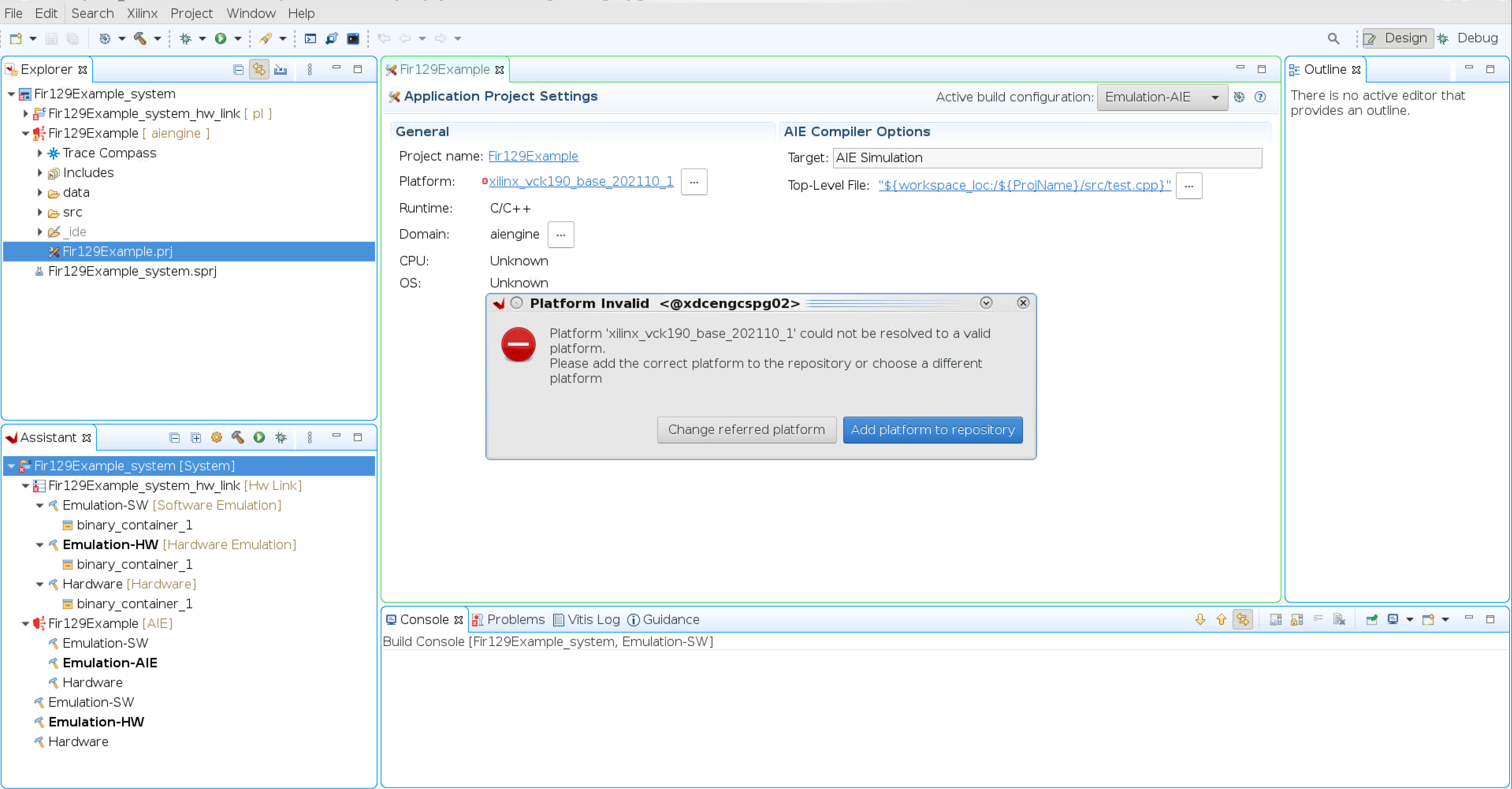
In the Vitis IDE, expand the Fir129Example [ aiengine ] project and double-click the Fir129Example.prj file.
On the Platform Invalid prompt, select Add platform to repository.
Navigate to the installed vck190 platform file (.xpfm).
Note
The VCK190 base platform must be downloaded from the Xilinx lounge.
Set the Active configuration to Emulation-AIE for the design.
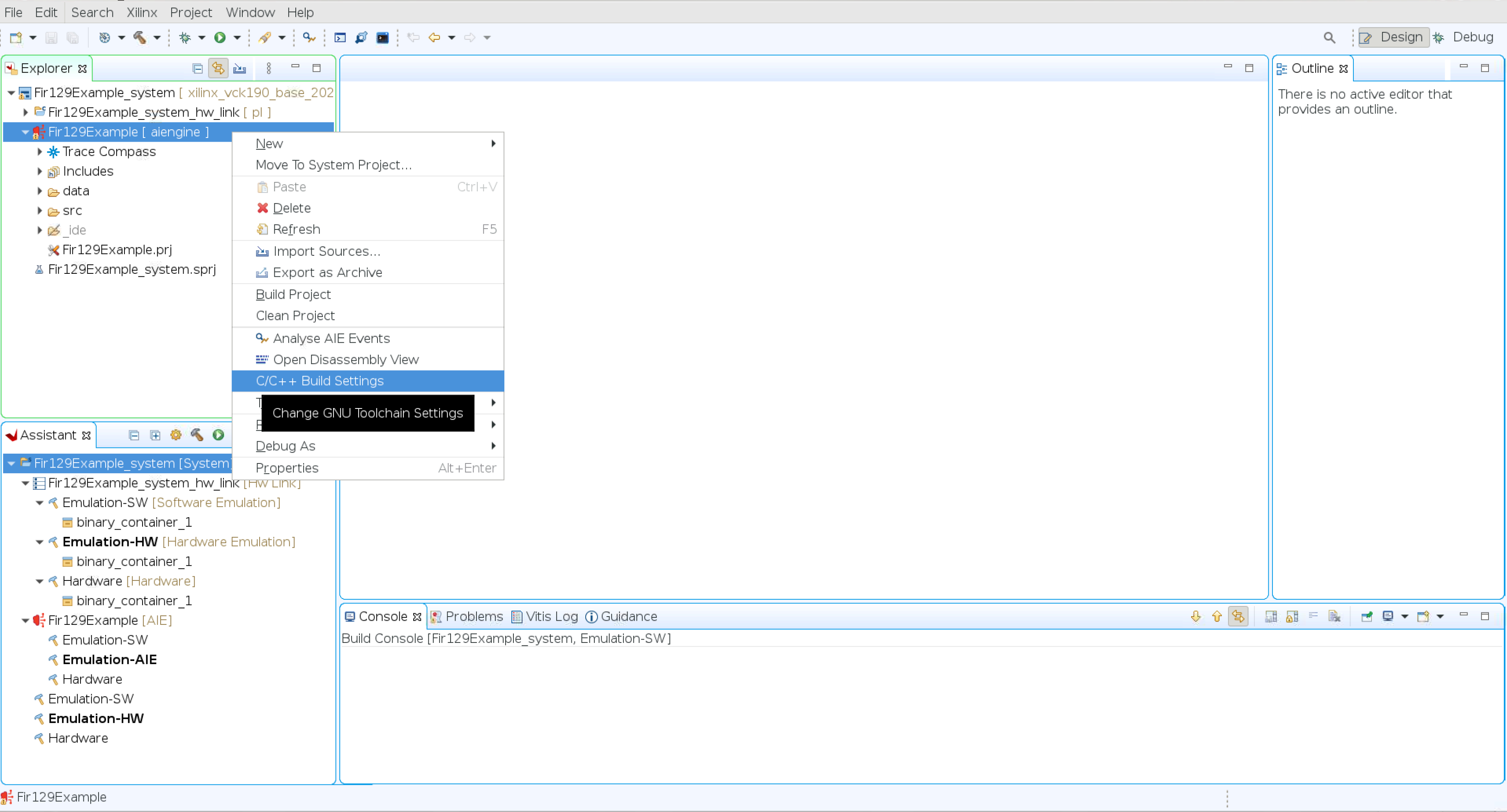
Right-click the Fir129Example [ aiengine ] and select C/C++ Build Settings → Manage Configurations → Select Emulation-AIE → Set Active.
Click OK.
Select Apply and Close.
Build the project by right-clicking the Fir129Example [ aiengine] project and select Build Project.
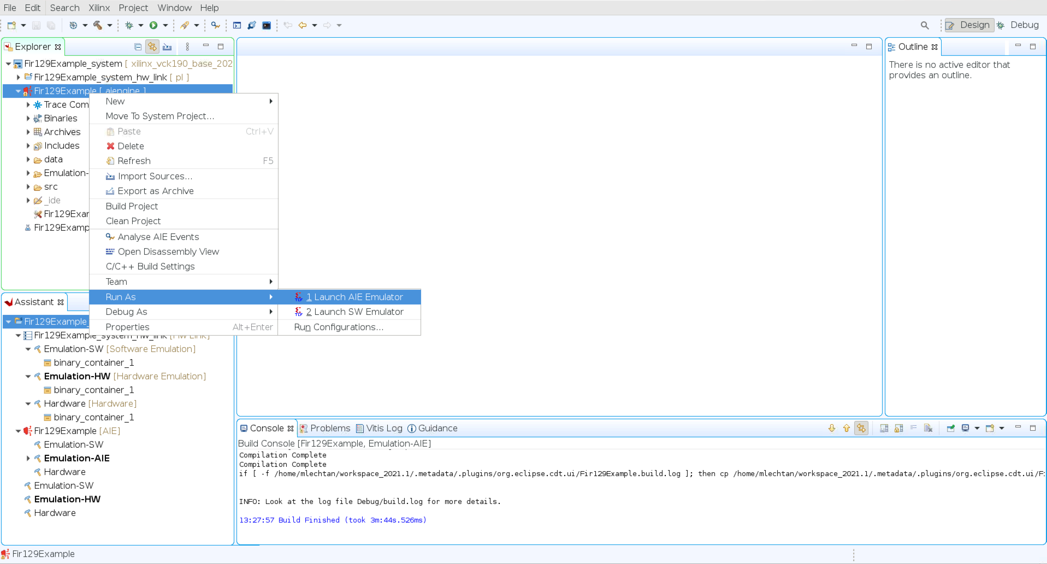
Perform simulation after the project is built by right-clicking the Fir129Example [ aiengine ] project and select Run As → 1. Launch AIE Emulator
After simulation is complete, navigate to Fir129Example [ aiengine] → Emulation-AIE → aiesimulator_output → data and compare output.txt with the fir_out_ref.txt file in the data folder.
Example Graph Coding
The following example can be used as a template for graph coding:
test.h
#include <adf.h>
#include "fir_sr_sym_graph.hpp"

#define FIR129_LENGTH 129
#define FIR129_SHIFT 15
#define FIR129_ROUND_MODE 0
#define FIR129_INPUT_SAMPLES 256

using namespace adf ;
namespace testcase {
    class test_kernel: public graph {
       private:
       // FIR coefficients
       std::vector<int16> m_taps   = std::vector<int16>{
                -1, -3, 3, -1, -3, 6, -1, -7, 9, -1, -12, 14, 1, -20, 19, 5,
                -31, 26, 12, -45, 32, 23, -63, 37, 40, -86, 40, 64, -113, 39, 96, -145,
                33, 139, -180, 17, 195, -218, -9, 266, -258, -53, 357, -299, -118, 472, -339, -215,
                620, -376, -360, 822, -409, -585, 1118, -437, -973, 1625, -458, -1801, 2810, -470, -5012, 10783,
                25067};
       //FIR Graph class
       xf::dsp::aie::fir::sr_sym::fir_sr_sym_graph<cint16, int16,
       FIR129_LENGTH, FIR129_SHIFT, FIR129_ROUND_MODE, FIR129_INPUT_SAMPLES>
       firGraph;
       public:
       port<input> in;
       port<output> out;
       // Constructor - with FIR graph class initialization
       test_kernel():firGraph(m_taps) {
          // Make connections
          // Size of window in Bytes.
          // Margin gets automatically added within the FIR graph class.
          // Margin equals to FIR length rounded up to nearest multiple of 32
          Bytes.
          connect<>(in, firGraph.in);
          connect<>(firGraph.out, out);
       };
    };
};
test.cpp
#include "test.h"

simulation::platform<1,1> platform("data/input.txt", "data/output.txt");
testcase::test_kernel filter ;

connect<> net0(platform.src[0], filter.in);
connect<> net1(filter.out, platform.sink[0]);

int main(void) {
    filter.init() ;
    filter.run() ;
    filter.end() ;
    return 0 ;
}