Overview
The Vitis vision library has been designed to work in the Vitis development environment, and provides a software interface for computer vision functions accelerated on an FPGA device. Vitis vision library functions are mostly similar in functionality to their OpenCV equivalent. Any deviations, if present, are documented.
See also
For more information on the Vitis vision library please refer Prerequisites section
To familiarize yourself with the steps required to use the Vitis vision library functions, see the Using the Vitis vision Library.
Basic Features
All Vitis vision library functions follow a common format. The following properties hold true for all the functions.
- All the functions are designed as templates and all arguments that
are images, must be provided as
xf::cv::Mat. - All functions are defined in the
xf::cvnamespace. - Some of the major template arguments are:
- Maximum size of the image to be processed
- Datatype defining the properties of each pixel
- Number of pixels to be processed per clock cycle
- Other compile-time arguments relevent to the functionality.
The Vitis vision library contains enumerated datatypes which enables you to
configure xf::cv::Mat. For more details on xf::cv::Mat, see the xf::cv::Mat
Image Container Class.
Vitis Vision Kernel on Vitis
The Vitis vision library is designed to be used with the Vitis development environment.
The OpenCL host code is written in the testbench file, whereas the calls to Vitis
Vision functions are done from the accel file.
The image containers for Vitis vision library functions are xf::cv::Mat
objects. For more information, see the xf::cv::Mat Image Container
Class.
Vitis Vision Library Contents
The following table lists the contents of the Vitis vision library.
| Folder | Details |
|---|---|
| L1/examples | Contains the sample testbench code to facilitate running unit tests on Vitis/Vivado HLS. The examples/ has folders with algorithm names. Each algorithm folder contains testbench, accel, config, Makefile , Json file and a ‘build’ folder. |
| L1/include/aie | Contains the infrastructure headers and AIE kernel definitions |
| L1/include/common | Contains the common library infrastructure headers, such as types specific to the library. |
| L1/include/core | Contains the core library
functionality headers, such as
the math functions. |
| L1/include/features | Contains the feature extraction
kernel function definitions. For
example, Harris. |
| L1/include/imgproc | Contains all the kernel function definitions related to image proce ssing definitions. |
| L1/include/video | Contains all the kernel function definitions, related to video proc essing functions.eg:Optical flow |
| L1/include/dnn | Contains all the kernel function definitions, related to deep lea rning preprocessing. |
| L1/tests | Contains all test folders to run simulations, synthesis and export RTL.The tests folder contains the folders with algorithm names.Each algorithm folder further contains configuration folders, that has makefile and tcl files to run tests. |
| L1/examples/build | Contains xf_config_params.h file, which has configurable macros and varibales related to the particula r example. |
| L1/lib/sw | Contains the AIE data-movers library object files |
| L2/examples | Contains the sample testbench code to facilitate running unit tests on Vitis. The examples/ contains the folders with algorithm names. Each algorithm folder contains testbench, accel, config, Makefile , Json file and a ‘build’ folder. |
| L2/tests | Contains all test folders to run software, hardware emulations and hardware build. The tests cont ains folders with algorithm names. Each algorithm folder further cont ains configuration folders, that has makefile and config files to run PL tests. |
| L2/tests/aie | Contains all test folders to run x86 simulation, hardware emulation and hardware build. The tests cont ains folders with algorithm names. Each algorithm folder further cont ains configuration folders, that has makefile, testbench, config and other required files to run the AIE tests |
| L2/examples/build | Contains xf_config_params.h file, which has configurable macros and varibales related to the particula r example. |
| L3/examples | Contains the sample testbench code to build pipeline functions on Vitis. The examples/ contains the folders with algorithm names. Each algorithm folder contains testbench, accel, config, Makefile , Json file and a ‘build’ folder. |
| L3/tests | Contains all test folders to run software, hardware emulations and hardware build.The tests cont ains folders with algorithm names. Each algorithm name folder contai ns the configuration folders, inside configuration folders makefile is present to run tests. |
| L3/examples/build | Contains xf_config_params.h file, which has configurable macros and varibales related to the particula r example. |
| L3/benchmarks | Contains benchmark examples to compare the software implementation versus FPGA implementation using Vitis vision library. |
| ext | Contains the utility functions related to opencl hostcode. |
Getting Started with Vitis Vision
Describes the methodology to create a kernel, corresponding host code and a suitable makefile to compile an Vitis Vision kernel for any of the supported platforms in Vitis. The subsequent section also explains the methodology to verify the kernel in various emulation modes and on the hardware.
Prerequisites
- Valid installation of Vitis™ 2021.2 or later version and the corresponding licenses.
- Install the Vitis Vision libraries, if you intend to use libraries compiled differently than what is provided in Vitis.
- Install the card for which the platform is supported in Vitis 2021.2 or later versions.
- If targeting an embedded platform, set up the evaluation board.
- Xilinx® Runtime (XRT) must be installed. XRT provides software interface to Xilinx FPGAs.
- Install/compile OpenCV libraries(with compatible libjpeg.so). Appropriate version (X86/aarch32/aarch64) of compiler must be used based on the available processor for the target board.
- libOpenCL.so must be installed if not present along with the platform.
Note
All Vitis Vision functions were tested against OpenCV version - 4.4.0
Vitis Design Methodology
There are three critical components in making a kernel work on a platform using Vitis™:
- Host code with OpenCL constructs
- Wrappers around HLS Kernel(s)
- Makefile to compile the kernel for emulation or running on hardware.
Host Code with OpenCL
Host code is compiled for the host machine that runs on the host and provides the data and control signals to the attached hardware with the FPGA. The host code is written using OpenCL constructs and provides capabilities for setting up, and running a kernel on the FPGA. The following functions are executed using the host code:
- Loading the kernel binary on the FPGA – xcl::import_binary_file() loads the bitstream and programs the FPGA to enable required processing of data.
- Setting up memory buffers for data transfer – Data needs to be sent and read from the DDR memory on the hardware. cl::Buffers are created to allocate required memory for transferring data to and from the hardware.
- Transfer data to and from the hardware –enqueueWriteBuffer() and enqueueReadBuffer() are used to transfer the data to and from the hardware at the required time.
- Execute kernel on the FPGA – There are functions to execute kernels on the FPGA. There can be single kernel execution or multiple kernel execution that could be asynchronous or synchronous with each other. Commonly used command is enqueueTask().
- Profiling the performance of kernel execution – The host code in OpenCL also enables measurement of the execution time of a kernel on the FPGA. The function used in our examples for profiling is getProfilingInfo().
Wrappers around HLS Kernel(s)
All Vitis Vision kernels are provided with C++ function templates (located at <Github repo>/include) with image containers as objects of xf::cv::Mat class. In addition, these kernels will work either in stream based (where complete image is read continuously) or memory mapped (where image data access is in blocks).
Vitis flow (OpenCL) requires kernel interfaces to be memory pointers with width in power(s) of 2. So glue logic is required for converting memory pointers to xf::cv::Mat class data type and vice-versa when interacting with Vitis Vision kernel(s). Wrapper(s) are build over the kernel(s) with this glue logic. Below examples will provide a methodology to handle different kernel (Vitis Vision kernels located at <Github repo>/include) types (stream and memory mapped).
Stream Based Kernels
To facilitate the conversion of pointer to xf::Mat and vice versa, two adapter functions are included as part of Vitis Vision xf::cv::Array2xfMat() and xf::cv::xfMat2Array(). It is necessary for the xf::Mat objects to be invoked as streams using HLS pragma with a minimum depth of 2. This results in a top-level (or wrapper) function for the kernel as shown below:
extern “C”
{
void func_top (ap_uint *gmem_in, ap_uint *gmem_out, ...) {
xf::cv::Mat<…> in_mat(…), out_mat(…);
#pragma HLS dataflow
xf::cv::Array2xfMat<…> (gmem_in, in_mat);
xf::cv::Vitis Vision-func<…> (in_mat, out_mat…);
xf::cv::xfMat2Array<…> (gmem_out, out_mat);
}
}
The above illustration assumes that the data in xf::cv::Mat is being streamed in and streamed out. You can also create a pipeline with multiple functions in pipeline instead of just one Vitis Vision function.
For the stream based kernels with different inputs of different sizes, multiple instances of the adapter functions are necessary. For this,
extern “C” {
void func_top (ap_uint *gmem_in1, ap_uint *gmem_in2, ap_uint *gmem_in3, ap_uint *gmem_out, ...) {
xf::cv::Mat<...,HEIGHT,WIDTH,…> in_mat1(…), out_mat(…);
xf::cv::Mat<...,HEIGHT/4,WIDTH,…>  in_mat2(…), in_mat3(…);
#pragma HLS dataflow
xf::cv::accel_utils obj_a, obj_b;
obj_a.Array2xfMat<…,HEIGHT,WIDTH,…> (gmem_in1, in_mat1);
obj_b.Array2xfMat<…,HEIGHT/4,WIDTH,…> (gmem_in2, in_mat2);
obj_b.Array2xfMat<…,HEIGHT/4,WIDTH,…> (gmem_in3, in_mat3);
xf::cv::Vitis-Vision-func(in_mat1, in_mat2, int_mat3, out_mat…);
xf::cv::xfMat2Array<…> (gmem_out, out_mat);
}
}
For the stream based implementations, the data must be fetched from the input AXI and must be pushed to xfMat as required by the xfcv kernels for that particular configuration. Likewise, the same operations must be performed for the output of the xfcv kernel. To perform this, two utility functions are provided, xf::cv::Array2xfMat() and xf::cv::xfMat2Array().
Array2xfMat
This function converts the input array to xf::cv::Mat. The Vitis Vision kernel would require the input to be of type, xf::cv::Mat. This function would read from the array pointer and write into xf::cv::Mat based on the particular configuration (bit-depth, channels, pixel-parallelism) the xf::cv::Mat was created. Array2xfMat supports line stride. Line stride is the number of pixels which needs to be added to the address in the first pixel of a row in order to access the first pixel of the next row.
//Without Line stride support
template <int PTR_WIDTH, int MAT_T, int ROWS, int COLS, int NPC>
void Array2xfMat(ap_uint< PTR_WIDTH > *srcPtr, xf::cv::Mat<MAT_T,ROWS,COLS,NPC>& dstMat)

//With Line stride support
template <int PTR_WIDTH, int MAT_T, int ROWS, int COLS, int NPC>
void Array2xfMat(ap_uint< PTR_WIDTH > *srcPtr, xf::cv::Mat<MAT_T,ROWS,COLS,NPC>& dstMat, int stride)
| Parameter | Description |
|---|---|
| PTR_WIDTH | Data width of the input pointer. The value must be power 2, starting from 8 to 512. |
| MAT_T | Input Mat type. Example XF_8UC1, XF_16UC1, XF_8UC3 and XF_8UC4 |
| ROWS | Maximum height of image |
| COLS | Maximum width of image |
| NPC | Number of pixels computed in parallel. Example XF_NPPC1, XF_NPPC8 |
| srcPtr | Input pointer. Type of the pointer based on the PTR_WIDTH. |
| dstMat | Output image of type xf::cv::Mat |
| stride | Line stride. Default value is dstMat.cols |
xfMat2Array
This function converts the input xf::cv::Mat to output array. The output of the xf::kernel function will be xf::cv::Mat, and it will require to convert that to output pointer. xfMat2Array supports line stride. Line stride is the number of pixels which needs to be added to the address in the first pixel of a row in order to access the first pixel of the next row.
//Without Line stride support
template <int PTR_WIDTH, int MAT_T, int ROWS, int COLS, int NPC, int FILLZERO = 1>
void xfMat2Array(xf::cv::Mat<MAT_T,ROWS,COLS,NPC>& srcMat, ap_uint< PTR_WIDTH > *dstPtr)

//With Line stride support
template <int PTR_WIDTH, int MAT_T, int ROWS, int COLS, int NPC, int FILLZERO = 1>
void xfMat2Array(xf::cv::Mat<MAT_T,ROWS,COLS,NPC>& srcMat, ap_uint< PTR_WIDTH > *dstPtr, int stride)
| Parameter | Description |
|---|---|
| PTR_WIDTH | Data width of the output pointer. The value must be power 2, from 8 to 512. |
| MAT_T | Input Mat type. Example XF_8UC1, XF_16UC1, XF_8UC3 and XF_8UC4 |
| ROWS | Maximum height of image |
| COLS | Maximum width of image |
| NPC | Number of pixels computed in parallel. Example XF_NPPC1, XF_NPPC8 |
| FILLZERO | Line padding Flag. Use when line stride support is needed. Default value is 1 |
| dstPtr | Output pointer. Type of the pointer based on the PTR_WIDTH. |
| srcMat | Input image of type xf::cv::Mat |
| stride | Line stride. Default value is srcMat.cols |
Interface pointer widths
Minimum pointer widths for different configurations is shown in the following table:
| MAT type | Parallelism | Min PTR_WIDTH | Max PTR_WIDTH |
|---|---|---|---|
| XF_8UC1 | XF_NPPC1 | 8 | 512 |
| XF_16UC1 | XF_NPPC1 | 16 | 512 |
| XF_ 8UC1 | XF_NPPC8 | 64 | 512 |
| XF_ 16UC1 | XF_NPPC8 | 128 | 512 |
| XF_ 8UC3 | XF_NPPC1 | 32 | 512 |
| XF_ 8UC3 | XF_NPPC8 | 256 | 512 |
| XF_8UC4 | XF_NPPC8 | 256 | 512 |
| XF_8UC3 | XF_NPPC16 | 512 | 512 |
Kernel-to-Kernel streaming
There are two utility functions available in Vitis Vision, axiStrm2xfMat and xfMat2axiStrm to support streaming of data between two kernels. For more details on kernel-to-kernel streaming, refer to the “Streaming Data Transfers Between the Kernels” section of [UG1393](https://www.xilinx.com/support/documentation/sw_manuals/xilinx2021_1/ug1393-vitis-application-acceleration.pdf) document.
axiStrm2xfMat
axiStrm2xfMat is used by consumer kernel to support streaming data transfer between two kernels. Consumer kernel receives data from producer kernel through kernel streaming interface which is defined by hls:stream with the ap_axiu< PTR_WIDTH, 0, 0, 0> data type. axiStrm2xfMat would read from AXI stream and write into xf::cv:Mat based on particular configuration (bit-depth, channels, pixel-parallelism) the xf::cv:Mat was created.
template <int PTR_WIDTH, int MAT_T, int ROWS, int COLS, int NPC>
void axiStrm2xfMat(hls::stream<ap_axiu<PTR_WIDTH, 0, 0, 0> >& srcPtr, xf::cv::Mat<MAT_T, ROWS, COLS, NPC>& dstMat)
| Parameter | Description |
|---|---|
| PTR_WIDTH | Data width of the input pointer. The value must be power 2, starting from 8 to 512. |
| MAT_T | Input Mat type. Example XF_8UC1, XF_16UC1, XF_8UC3 and XF_8UC4 |
| ROWS | Maximum height of image |
| COLS | Maximum width of image |
| NPC | Number of pixels computed in parallel. Example XF_NPPC1, XF_NPPC8 |
| srcPtr | Input image of type hls::stream<ap_axiu<PTR_WIDTH, 0, 0, 0> > |
| dstMat | Output image of type xf::cv::Mat |
xfMat2axiStrm
xfMat2axiStrm is used by producer kernel to support streaming data transfer between two kernels. This function converts the input xf:cv::Mat to AXI stream based on particular configuration (bit-depth, channels, pixel-parallelism).
template <int PTR_WIDTH, int MAT_T, int ROWS, int COLS, int NPC>
void xfMat2axiStrm(xf::cv::Mat<MAT_T, ROWS, COLS, NPC>& srcMat, hls::stream<ap_axiu<PTR_WIDTH, 0, 0, 0> >& dstPtr)
| Parameter | Description |
|---|---|
| PTR_WIDTH | Data width of the input pointer. The value must be power 2, starting from 8 to 512. |
| MAT_T | Input Mat type. Example XF_8UC1, XF_16UC1, XF_8UC3 and XF_8UC4 |
| ROWS | Maximum height of image |
| COLS | Maximum width of image |
| NPC | Number of pixels computed in parallel. Example XF_NPPC1, XF_NPPC8 |
| srcPtr | Input image of type hls::stream<ap_axiu<PTR_WIDTH, 0, 0, 0> > |
| dstMat | Output image of type xf::cv::Mat |
Memory Mapped Kernels
In the memory map based kernels such as crop, Mean-shift tracking and bounding box, the input read will be for particular block of memory based on the requirement for the algorithm. The streaming interfaces will require the image to be read in raster scan manner, which is not the case for the memory mapped kernels. The methodology to handle this case is as follows:
extern “C”
{
void func_top (ap_uint *gmem_in, ap_uint *gmem_out, ...) {
xf::cv::Mat<…> in_mat(…,gmem_in), out_mat(…,gmem_out);
xf::cv::kernel<…> (in_mat, out_mat…);
}
}
The gmem pointers must be mapped to the xf::cv::Mat objects during the object creation, and then the memory mapped kernels are called with these mats at the interface. It is necessary that the pointer size must be same as the size required for the xf::Vitis-Vision-func, unlike the streaming method where any higher size of the pointers (till 512-bits) are allowed.
Makefile
Examples for makefile are provided in the examples and tests section of GitHub.
Design example Using Library on Vitis
Following is a multi-kernel example, where different kernel runs sequentially in a pipeline to form an application. This example performs Canny edge detection, where two kernels are involved, Canny and edge tracing. Canny function will take gray-scale image as input and provided the edge information in 3 states (weak edge (1), strong edge (3), and background (0)), which is being fed into edge tracing, which filters out the weak edges. The prior works in a streaming based implementation and the later in a memory mapped manner.
Host code
The following is the Host code for the canny edge detection example. The host code sets up the OpenCL platform with the FPGA of processing required data. In the case of Vitis Vision example, the data is an image. Reading and writing of images are enabled using called to functions from Vitis Vision.
// setting up device and platform
    std::vector<cl::Device> devices = xcl::get_xil_devices();
    cl::Device device = devices[0];
    cl::Context context(device);
    cl::CommandQueue q(context, device,CL_QUEUE_PROFILING_ENABLE);
    std::string device_name = device.getInfo<CL_DEVICE_NAME>();

    // Kernel 1: Canny
    std::string binaryFile=xcl::find_binary_file(device_name,"krnl_canny");
    cl::Program::Binaries bins = xcl::import_binary_file(binaryFile);
    devices.resize(1);
    cl::Program program(context, devices, bins);
    cl::Kernel krnl(program,"canny_accel");

    // creating necessary cl buffers for input and output
    cl::Buffer imageToDevice(context, CL_MEM_READ_ONLY,(height*width));
    cl::Buffer imageFromDevice(context, CL_MEM_WRITE_ONLY,(height*width/4));


    // Set the kernel arguments
    krnl.setArg(0, imageToDevice);
    krnl.setArg(1, imageFromDevice);
    krnl.setArg(2, height);
    krnl.setArg(3, width);
    krnl.setArg(4, low_threshold);
    krnl.setArg(5, high_threshold);

    // write the input image data from host to device memory
    q.enqueueWriteBuffer(imageToDevice, CL_TRUE, 0,(height*(width)),img_gray.data);
    // Profiling Objects
    cl_ulong start= 0;
    cl_ulong end = 0;
    double diff_prof = 0.0f;
    cl::Event event_sp;

    // Launch the kernel
    q.enqueueTask(krnl,NULL,&event_sp);
    clWaitForEvents(1, (const cl_event*) &event_sp);

    // profiling
    event_sp.getProfilingInfo(CL_PROFILING_COMMAND_START,&start);
    event_sp.getProfilingInfo(CL_PROFILING_COMMAND_END,&end);
    diff_prof = end-start;
    std::cout<<(diff_prof/1000000)<<"ms"<<std::endl;

    // Kernel 2: edge tracing
    cl::Kernel krnl2(program,"edgetracing_accel");

    cl::Buffer imageFromDeviceedge(context, CL_MEM_WRITE_ONLY,(height*width));

    // Set the kernel arguments
    krnl2.setArg(0, imageFromDevice);
    krnl2.setArg(1, imageFromDeviceedge);
    krnl2.setArg(2, height);
    krnl2.setArg(3, width);

    // Profiling Objects
    cl_ulong startedge= 0;
    cl_ulong endedge = 0;
    double diff_prof_edge = 0.0f;
    cl::Event event_sp_edge;

    // Launch the kernel
    q.enqueueTask(krnl2,NULL,&event_sp_edge);
    clWaitForEvents(1, (const cl_event*) &event_sp_edge);

    // profiling
    event_sp_edge.getProfilingInfo(CL_PROFILING_COMMAND_START,&startedge);
    event_sp_edge.getProfilingInfo(CL_PROFILING_COMMAND_END,&endedge);
    diff_prof_edge = endedge-startedge;
    std::cout<<(diff_prof_edge/1000000)<<"ms"<<std::endl;


    //Copying Device result data to Host memory
    q.enqueueReadBuffer(imageFromDeviceedge, CL_TRUE, 0,(height*width),out_img_edge.data);
    q.finish();
Top level kernel
Below is the top-level/wrapper function with all necessary glue logic.
// streaming based kernel
#include "xf_canny_config.h"

extern "C" {
void canny_accel(ap_uint<INPUT_PTR_WIDTH> *img_inp, ap_uint<OUTPUT_PTR_WIDTH> *img_out, int rows, int cols,int low_threshold,int high_threshold)
{
#pragma HLS INTERFACE m_axi     port=img_inp  offset=slave bundle=gmem1
#pragma HLS INTERFACE m_axi     port=img_out  offset=slave bundle=gmem2
#pragma HLS INTERFACE s_axilite port=img_inp  bundle=control
#pragma HLS INTERFACE s_axilite port=img_out  bundle=control

#pragma HLS INTERFACE s_axilite port=rows     bundle=control
#pragma HLS INTERFACE s_axilite port=cols     bundle=control
#pragma HLS INTERFACE s_axilite port=low_threshold     bundle=control
#pragma HLS INTERFACE s_axilite port=high_threshold     bundle=control
#pragma HLS INTERFACE s_axilite port=return   bundle=control

    xf::cv::Mat<XF_8UC1, HEIGHT, WIDTH, INTYPE> in_mat(rows,cols);

    xf::cv::Mat<XF_2UC1, HEIGHT, WIDTH, XF_NPPC32> dst_mat(rows,cols);

    #pragma HLS DATAFLOW

    xf::cv::Array2xfMat<INPUT_PTR_WIDTH,XF_8UC1,HEIGHT,WIDTH,INTYPE>(img_inp,in_mat);
    xf::cv::Canny<FILTER_WIDTH,NORM_TYPE,XF_8UC1,XF_2UC1,HEIGHT, WIDTH,INTYPE,XF_NPPC32,XF_USE_URAM>(in_mat,dst_mat,low_threshold,high_threshold);
    xf::cv::xfMat2Array<OUTPUT_PTR_WIDTH,XF_2UC1,HEIGHT,WIDTH,XF_NPPC32>(dst_mat,img_out);


}
}
// memory mapped kernel
#include "xf_canny_config.h"
extern "C" {
void edgetracing_accel(ap_uint<INPUT_PTR_WIDTH> *img_inp, ap_uint<OUTPUT_PTR_WIDTH> *img_out, int rows, int cols)
{
#pragma HLS INTERFACE m_axi     port=img_inp  offset=slave bundle=gmem3
#pragma HLS INTERFACE m_axi     port=img_out  offset=slave bundle=gmem4
#pragma HLS INTERFACE s_axilite port=img_inp  bundle=control
#pragma HLS INTERFACE s_axilite port=img_out  bundle=control

#pragma HLS INTERFACE s_axilite port=rows     bundle=control
#pragma HLS INTERFACE s_axilite port=cols     bundle=control
#pragma HLS INTERFACE s_axilite port=return   bundle=control


    xf::cv::Mat<XF_2UC1, HEIGHT, WIDTH, XF_NPPC32> _dst1(rows,cols,img_inp);
    xf::cv::Mat<XF_8UC1, HEIGHT, WIDTH, XF_NPPC8> _dst2(rows,cols,img_out);
    xf::cv::EdgeTracing<XF_2UC1,XF_8UC1,HEIGHT, WIDTH, XF_NPPC32,XF_NPPC8,XF_USE_URAM>(_dst1,_dst2);

}
}
Evaluating the Functionality
You can build the kernels and test the functionality through software emulation, hardware emulation, and running directly on a supported hardware with the FPGA. Use the following commands to setup the basic environment:
$ cd <path to the folder where makefile is present>
$ source <path to the Vitis installation folder>/Vitis/<version number>/settings64.sh
$ export DEVICE=<path-to-platform-directory>/<platform>.xpfm
For PCIe devices, set the following:
$ source <path to Xilinx_xrt>/setup.sh

$ export OPENCV_INCLUDE=< path-to-opencv-include-folder >

$ export OPENCV_LIB=< path-to-opencv-lib-folder >

$ export LD_LIBRARY_PATH=$LD_LIBRARY_PATH:< path-to-opencv-lib-folder >
For embedded devices, set the following:
Download the platform, and common-image from Xilinx Download Center. Run the sdk.sh script from the common-image directory to install sysroot using the command :
$ ./sdk.sh -y -d ./ -p

Unzip the rootfs file :
$ gunzip ./rootfs.ext4.gz

$ export SYSROOT=< path-to-platform-sysroot >

$ export EDGE_COMMON_SW=< path-to-rootfs-and-Image-files >

$ export PERL=<path-to-perl-installation-location> #For example, "export PERL=/usr/bin/perl". Please make sure that Expect.pm package is available in your Perl installation.
Software Emulation
Software emulation is equivalent to running a C-simulation of the kernel. The time for compilation is minimal, and is therefore recommended to be the first step in testing the kernel. Following are the steps to build and run for the software emulation:
For PCIe devices:
$ make host xclbin TARGET=sw_emu

$ make run TARGET=sw_emu
For embedded devices:
$ make host xclbin TARGET=sw_emu HOST_ARCH=< aarch32 | aarch64 >

$ make run TARGET=sw_emu HOST_ARCH=< aarch32 | aarch64 >
Hardware Emulation
Hardware emulation runs the test on the generated RTL after synthesis of the C/C++ code. The simulation, since being done on RTL requires longer to complete when compared to software emulation. Following are the steps to build and run for the hardware emulation:
For PCIe devices:
$ make host xclbin TARGET=hw_emu

$ make run TARGET=hw_emu
For embedded devices:
$ make host xclbin TARGET=hw_emu HOST_ARCH=< aarch32 | aarch64 >

$ make run TARGET=hw_emu HOST_ARCH=< aarch32 | aarch64 >
Testing on the Hardware
To test on the hardware, the kernel must be compiled into a bitstream (building for hardware). This would consume some time since the C/C++ code must be converted to RTL, run through synthesis and implementation process before a bitstream is created. As a prerequisite the drivers has to be installed for corresponding XSA, for which the example was built for. Following are the steps to build the kernel and run on a hardware:
For PCIe devices:
$ make host xclbin TARGET=hw

$ make run TARGET=hw
For embedded devices:
$ make host xclbin TARGET=hw HOST_ARCH=< aarch32 | aarch64 >

$ make run TARGET=< sw_emu|hw_emu|hw > HOST_ARCH=< aarch32 | aarch64 > #This command will generate only the sd_card folder in case of hardware build.
Note. For hw run on embedded devices, copy the generated sd_card folder content under package_hw to an SD Card. More information on preparing the SD Card is available [here](https://xilinx-wiki.atlassian.net/wiki/spaces/A/pages/18842385/How+to+format+SD+card+for+SD+boot#HowtoformatSDcardforSDboot-CopingtheImagestotheNewPartitions). After successful booting of the board, run the following commands:
cd /mnt
export XCL_BINDIR=< xclbin-folder-present-in-the-sd_card > #For example, “export XCL_BINDIR=xclbin_zcu102_base_hw”
./run_script.sh
Using the Vitis vision Library
This section describes using the Vitis vision library in the Vitis development environment.
Note: The instructions in this section assume that you have downloaded and installed all the required packages.
include folder constitutes all the necessary components to build a Computer Vision or Image Processing pipeline using the library. The folders common and core contain the infrastructure that the library functions need for basic functions, Mat class, and macros. The library functions are categorized into 4 folders, features, video, dnn, and imgproc based on the operation they perform. The names of the folders are self-explanatory.
To work with the library functions, you need to include the path to the the include folder in the Vitis project. You can include relevant header files for the library functions you will be working with after you source the include folder’s path to the compiler. For example, if you would like to work with Harris Corner Detector and Bilateral Filter, you must use the following lines in the host code:
#include “features/xf_harris.hpp” //for Harris Corner Detector
#include “imgproc/xf_bilateral_filter.hpp” //for Bilateral Filter
#include “video/xf_kalmanfilter.hpp”
After the headers are included, you can work with the library functions as described in the Vitis vision Library API Reference using the examples in the examples folder as reference.
The following table gives the name of the header file, including the folder name, which contains the library function.
| Function Name | File Path in the include folder |
|---|---|
| xf::cv::accumulate | imgproc/xf_accumulate_image.hpp |
| xf::cv::accumulateSquare | imgproc/xf_accumulate_squared.hpp |
| xf::cv::accumulateWeighted | imgproc/xf_accumulate_weighted.hp p |
| xf::cv::absdiff, xf::cv::add, xf::cv::subtract, xf::cv::bitwise_and, xf::cv::bitwise_or, xf::cv::bitwise_not, xf::cv::bitwise_xor,xf::cv::multiply ,xf::cv::Max, xf::cv::Min,xf::cv::compare, xf::cv::zero, xf::cv::addS, xf::cv::SubS, xf::cv::SubRS ,xf::cv::compareS, xf::cv::MaxS, xf::cv::MinS, xf::cv::set | core/xf_arithm.hpp |
| xf::cv::addWeighted | imgproc/xf_add_weighted.hpp |
| xf::cv::autowhitebalance | imgproc/xf_autowhitebalance.hpp |
| xf::cv::autoexposurecorrection | imgproc/xf_aec.hpp |
| xf::cv::bilateralFilter | imgproc/xf_bilaterealfilter.hpp |
| xf::cv::blackLevelCorrection | imgproc/xf_black_level.hpp |
| xf::cv::bfmatcher | imgproc/xf_bfmatcher.hpp |
| xf::cv::boxFilter | imgproc/xf_box_filter.hpp |
| xf::cv::boundingbox | imgproc/xf_boundingbox.hpp |
| xf::cv::badpixelcorrection | imgproc/xf_bpc.hpp |
| xf::cv::Canny | imgproc/xf_canny.hpp |
| xf::cv::colorcorrectionmatrix | imgproc/xf_colorcorrectionmatrix. hpp |
| xf::cv::Colordetect | imgproc/xf_colorthresholding.hpp, imgproc/xf_bgr2hsv.hpp, imgproc/xf_erosion.hpp, imgproc/xf_dilation.hpp |
| xf::cv::merge | imgproc/xf_channel_combine.hpp |
| xf::cv::extractChannel | imgproc/xf_channel_extract.hpp |
| xf::cv::ccaCustom | imgproc/xf_cca_custom.hpp |
| xf::cv::clahe | imgproc/xf_clahe.hpp |
| xf::cv::convertTo | imgproc/xf_convert_bitdepth.hpp |
| xf::cv::crop | imgproc/xf_crop.hpp |
| xf::cv::distanceTransform | imgproc/xf_distancetransform.hpp |
| xf::cv::nv122iyuv, xf::cv::nv122rgba, xf::cv::nv122yuv4, xf::cv::nv212iyuv, xf::cv::nv212rgba, xf::cv::nv212yuv4, xf::cv::rgba2yuv4, xf::cv::rgba2iyuv, xf::cv::rgba2nv12, xf::cv::rgba2nv21, xf::cv::uyvy2iyuv, xf::cv::uyvy2nv12, xf::cv::uyvy2rgba, xf::cv::yuyv2iyuv, xf::cv::yuyv2nv12, xf::cv::yuyv2rgba, xf::cv::rgb2iyuv,xf::cv::rgb2nv12, xf::cv::rgb2nv21, xf::cv::rgb2yuv4, xf::cv::rgb2uyvy, xf::cv::rgb2yuyv, xf::cv::rgb2bgr, xf::cv::bgr2uyvy, xf::cv::bgr2yuyv, xf::cv::bgr2rgb, xf::cv::bgr2nv12, xf::cv::bgr2nv21, xf::cv::iyuv2nv12, xf::cv::iyuv2rgba, xf::cv::iyuv2rgb, xf::cv::iyuv2yuv4, xf::cv::nv122uyvy, xf::cv::nv122yuyv, xf::cv::nv122nv21, xf::cv::nv212rgb, xf::cv::nv212bgr, xf::cv::nv212uyvy, xf::cv::nv212yuyv, xf::cv::nv212nv12, xf::cv::uyvy2rgb, xf::cv::uyvy2bgr, xf::cv::uyvy2yuyv, xf::cv::yuyv2rgb, xf::cv::yuyv2bgr, xf::cv::yuyv2uyvy, xf::cv::rgb2gray, xf::cv::bgr2gray, xf::cv::gray2rgb, xf::cv::gray2bgr, xf::cv::rgb2xyz, xf::cv::bgr2xyz… | imgproc/xf_cvt_color.hpp |
| xf::cv::densePyrOpticalFlow | video/xf_pyr_dense_optical_flow.h pp |
| xf::cv::DenseNonPyrLKOpticalFlow | video/xf_dense_npyr_optical_flow. hpp |
| xf::cv::dilate | imgproc/xf_dilation.hpp |
| xf::cv::demosaicing | imgproc/xf_demosaicing.hpp |
| xf::cv::erode | imgproc/xf_erosion.hpp |
| xf::cv::fast | features/xf_fast.hpp |
| xf::cv::filter2D | imgproc/xf_custom_convolution.hpp |
| xf::cv::flip | features/xf_flip.hpp |
| xf::cv::GaussianBlur | imgproc/xf_gaussian_filter.hpp |
| xf::cv::gaincontrol | imgproc/xf_gaincontrol.hpp |
| xf::cv::gammacorrection | imgproc/xf_gammacorrection.hpp |
| xf::cv::gtm | imgproc/xf_gtm.hpp |
| xf::cv::cornerHarris | features/xf_harris.hpp |
| xf::cv::calcHist | imgproc/xf_histogram.hpp |
| xf::cv::equalizeHist | imgproc/xf_hist_equalize.hpp |
| xf::cv::extractExposureFrames | imgproc/xf_extract_eframes.hpp |
| xf::cv::HDRMerge_bayer | imgproc/xf_hdrmerge.hpp |
| xf::cv::HOGDescriptor | imgproc/xf_hog_descriptor.hpp |
| xf::cv::Houghlines | imgproc/xf_houghlines.hpp |
| xf::cv::inRange | imgproc/xf_inrange.hpp |
| xf::cv::integralImage | imgproc/xf_integral_image.hpp |
| xf::cv::KalmanFilter | video/xf_kalmanfilter.hpp |
| xf::cv::Lscdistancebased | imgproc/xf_lensshadingcorrection .hpp |
| xf::cv::LTM::process | imgproc/xf_ltm.hpp |
| xf::cv::LUT | imgproc/xf_lut.hpp |
| xf::cv::magnitude | core/xf_magnitude.hpp |
| xf::cv::MeanShift | imgproc/xf_mean_shift.hpp |
| xf::cv::meanStdDev | core/xf_mean_stddev.hpp |
| xf::cv::medianBlur | imgproc/xf_median_blur.hpp |
| xf::cv::minMaxLoc | core/xf_min_max_loc.hpp |
| xf::cv::modefilter | imgproc/xf_modefilter.hpp |
| xf::cv::OtsuThreshold | imgproc/xf_otsuthreshold.hpp |
| xf::cv::phase | core/xf_phase.hpp |
| xf::cv::preProcess | dnn/xf_pre_process.hpp |
| xf::cv::paintmask | imgproc/xf_paintmask.hpp |
| xf::cv::pyrDown | imgproc/xf_pyr_down.hpp |
| xf::cv::pyrUp | imgproc/xf_pyr_up.hpp |
| xf::cv::xf_QuatizationDithering | imgproc/xf_quantizationdithering .hpp |
| xf::cv::reduce | imgrpoc/xf_reduce.hpp |
| xf::cv::remap | imgproc/xf_remap.hpp |
| xf::cv::resize | imgproc/xf_resize.hpp |
| xf::cv::rgbir2bayer | imgproc/xf_rgbir.hpp |
| xf::cv::convertScaleAbs | imgproc/xf_convertscaleabs.hpp |
| xf::cv::Scharr | imgproc/xf_scharr.hpp |
| xf::cv::SemiGlobalBM | imgproc/xf_sgbm.hpp |
| xf::cv::Sobel | imgproc/xf_sobel.hpp |
| xf::cv::StereoPipeline | imgproc/xf_stereo_pipeline.hpp |
| xf::cv::sum | imgproc/xf_sum.hpp |
| xf::cv::StereoBM | imgproc/xf_stereoBM.hpp |
| xf::cv::SVM | imgproc/xf_svm.hpp |
| xf::cv::lut3d | imgproc/xf_3dlut.hpp |
| xf::cv::Threshold | imgproc/xf_threshold.hpp |
| xf::cv::warpTransform | imgproc/xf_warp_transform.hpp |
Changing the Hardware Kernel Configuration
To modify the configuration of any function, update the following file:
<path to vitis vision git folder>/vision/L1/examples/<function>/build/xf_config_params.h .
Using the Vitis vision Library Functions on Hardware
The following table lists the Vitis vision library functions and the command to run the respective examples on hardware. It is assumed that your design is completely built and the board has booted up correctly.
| Example | Function Name | Usage on Hardware |
|---|---|---|
| accumulate | xf::cv::accumulate | ./<executable name>.elf <path to input image 1> <path to input image 2> |
| accumulatesq uared | xf::cv::accumulateSquare | ./<executable name>.elf <path to input image 1> <path to input image 2> |
| accumulatewe ighted | xf::cv::accumulateWeighted | ./<executable name>.elf <path to input image 1> <path to input image 2> |
| addS | xf::cv::addS | ./<executable name>.elf <path to input image> |
| arithm | xf::cv::absdiff, xf::cv::subtract, xf::cv::bitwise_and, xf::cv::bitwise_or, xf::cv::bitwise_not, xf::cv::bitwise_xor | ./<executable name>.elf <path to input image 1> <path to input image 2> |
| addweighted | xf::cv::addWeighted | ./<executable name>.elf <path to input image 1> <path to input image 2> |
| Autoexposure correction | xf::cv::autoexposurecorr ection | ./<executable name>.elf <path to input image> |
| Autowhite balance | xf::cv::autowhitebalance | ./<executable name>.elf <path to input image> |
| Bilateralfil ter | xf::cv::bilateralFilter | ./<executable name>.elf <path to input image> |
| BlackLevel Correction | xf::cv::blackLevel Correction | ./<executable name>.elf <path to input image> |
| BruteForce | xf::cv::bfmatcher | ./<executable name>.elf <path to input image> |
| Boxfilter | xf::cv::boxFilter | ./<executable name>.elf <path to input image> |
| Badpixelcorr ection | xf::cv::badpixelcorrection | ./<executable name>.elf <path to input image> |
| Boundingbox | xf::cv::boundingbox | ./<executable name>.elf <path to input image> <No of ROI’s> |
| Canny | xf::cv::Canny | ./<executable name>.elf <path to input image> |
| ccaCustom | xf::cv::ccaCustom | ./<executable name>.elf <path to input image> |
| channelcombi ne | xf::cv::merge | ./<executable name>.elf <path to input image 1> <path to input image 2> <path to input image 3> <path to input image 4> |
| Channelextra ct | xf::cv::extractChannel | ./<executable name>.elf <path to input image> |
| CLAHE | xf::cv::clahe | ./<executable name>.elf <path to input image> |
| Colordetect | xf::cv::bgr2hsv, xf::cv::colorthresholding, xf::cv:: erode, xf::cv:: dilate | ./<executable name>.elf <path to input image> |
| color correction matrix | xf::cv::colorcorrection matrix | ./<executable name>.elf <path to input image> |
| compare | xf::cv::compare | ./<executable name>.elf <path to input image 1> <path to input image 2> |
| compareS | xf::cv::compareS | ./<executable name>.elf <path to input image> |
| Convertbitde pth | xf::cv::convertTo | ./<executable name>.elf <path to input image> |
| convertScale Abs | xf::cv::convertScaleAbs | ./<executable name>.elf <path to input image> |
| Cornertracke r | xf::cv::cornerTracker | ./exe <input video> <no. of frames> <Harris Threshold> <No. of frames after which Harris Corners are Reset> |
| crop | xf::cv::crop | ./<executable name>.elf <path to input image> |
| Customconv | xf::cv::filter2D | ./<executable name>.elf <path to input image> |
| cvtcolor IYUV2NV12 | xf::cv::iyuv2nv12 | ./<executable name>.elf <path to input image 1> <path to input image 2> <path to input image 3> |
| cvtcolor IYUV2RGBA | xf::cv::iyuv2rgba | ./<executable name>.elf <path to input image 1> <path to input image 2> <path to input image 3> |
| cvtcolor IYUV2YUV4 | xf::cv::iyuv2yuv4 | ./<executable name>.elf <path to input image 1> <path to input image 2> <path to input image 3> <path to input image 4> <path to input image 5> <path to input image 6> |
| cvtcolor NV122IYUV | xf::cv::nv122iyuv | ./<executable name>.elf <path to input image 1> <path to input image 2> |
| cvtcolor NV122RGBA | xf::cv::nv122rgba | ./<executable name>.elf <path to input image 1> <path to input image 2> |
| cvtcolor NV122YUV4 | xf::cv::nv122yuv4 | ./<executable name>.elf <path to input image 1> <path to input image 2> |
| cvtcolor NV212IYUV | xf::cv::nv212iyuv | ./<executable name>.elf <path to input image 1> <path to input image 2> |
| cvtcolor NV212RGBA | xf::cv::nv212rgba | ./<executable name>.elf <path to input image 1> <path to input image 2> |
| cvtcolor NV212YUV4 | xf::cv::nv212yuv4 | ./<executable name>.elf <path to input image 1> <path to input image 2> |
| cvtcolor RGBA2YUV4 | xf::cv::rgba2yuv4 | ./<executable name>.elf <path to input image> |
| cvtcolor RGBA2IYUV | xf::cv::rgba2iyuv | ./<executable name>.elf <path to input image> |
| cvtcolor RGBA2NV12 | xf::cv::rgba2nv12 | ./<executable name>.elf <path to input image> |
| cvtcolor RGBA2NV21 | xf::cv::rgba2nv21 | ./<executable name>.elf <path to input image> |
| cvtcolor UYVY2IYUV | xf::cv::uyvy2iyuv | ./<executable name>.elf <path to input image> |
| cvtcolor UYVY2NV12 | xf::cv::uyvy2nv12 | ./<executable name>.elf <path to input image> |
| cvtcolor UYVY2RGBA | xf::cv::uyvy2rgba | ./<executable name>.elf <path to input image> |
| cvtcolor YUYV2IYUV | xf::cv::yuyv2iyuv | ./<executable name>.elf <path to input image> |
| cvtcolor YUYV2NV12 | xf::cv::yuyv2nv12 | ./<executable name>.elf <path to input image> |
| cvtcolor YUYV2RGBA | xf::cv::yuyv2rgba | ./<executable name>.elf <path to input image> |
| Demosaicing | xf::cv::demosaicing | ./<executable name>.elf <path to input image> |
| Difference of Gaussian | xf::cv::GaussianBlur, xf::cv::duplicateMat, and xf::cv::subtract | ./<exe-name>.elf <path to input image> |
| Dilation | xf::cv::dilate | ./<executable name>.elf <path to input image> |
| Distance Transform | xf::cv::distanceTransform | ./<executable name>.elf <path to input image> |
| Erosion | xf::cv::erode | ./<executable name>.elf <path to input image> |
| FAST | xf::cv::fast | ./<executable name>.elf <path to input image> |
| Flip | xf::cv::flip | ./<executable name>.elf <path to input image> |
| Gaussianfilt er | xf::cv::GaussianBlur | ./<executable name>.elf <path to input image> |
| Gaincontrol | xf::cv::gaincontrol | ./<executable name>.elf <path to input image> |
| Gammacorrec tion | xf::cv::gammacorrection | ./<executable name>.elf <path to input image> |
| Global Tone Mapping | xf::cv::gtm | ./<executable name>.elf <path to input image> |
| Harris | xf::cv::cornerHarris | ./<executable name>.elf <path to input image> |
| Histogram | xf::cv::calcHist | ./<executable name>.elf <path to input image> |
| Histequializ e | xf::cv::equalizeHist | ./<executable name>.elf <path to input image> |
| Hog | xf::cv::HOGDescriptor | ./<executable name>.elf <path to input image> |
| Houghlines | xf::cv::HoughLines | ./<executable name>.elf <path to input image> |
| inRange | xf::cv::inRange | ./<executable name>.elf <path to input image> |
| Integralimg | xf::cv::integralImage | ./<executable name>.elf <path to input image> |
| Laplacian Filter | xf::cv::filter2d | ./<executable name>.elf <path to input image> |
| Lkdensepyrof | xf::cv::densePyrOpticalFlo w | ./<executable name>.elf <path to input image 1> <path to input image 2> |
| Lknpyroflow | xf::cv::DenseNonPyr LKOpticalFlow | ./<executable name>.elf <path to input image 1> <path to input image 2> |
| lensshading correction | xf::cv::Lscdistancebased | ./<executable name>.elf <path to input image> |
| Lut | xf::cv::LUT | ./<executable name>.elf <path to input image> |
| Local tone mapping | xf::cv::LTM::process | ./<executable name>.elf <path to input image> |
| Kalman Filter | xf::cv::KalmanFilter | ./<executable name>.elf |
| Magnitude | xf::cv::magnitude | ./<executable name>.elf <path to input image> |
| Max | xf::cv::Max | ./<executable name>.elf <path to input image 1> <path to input image 2> |
| MaxS | xf::cv::MaxS | ./<executable name>.elf <path to input image> |
| meanshifttra cking | xf::cv::MeanShift | ./<executable name>.elf <path to input video/input image files> <Number of objects to track> |
| meanstddev | xf::cv::meanStdDev | ./<executable name>.elf <path to input image> |
| medianblur | xf::cv::medianBlur | ./<executable name>.elf <path to input image> |
| Min | xf::cv::Min | ./<executable name>.elf <path to input image 1> <path to input image 2> |
| MinS | xf::cv::MinS | ./<executable name>.elf <path to input image> |
| Minmaxloc | xf::cv::minMaxLoc | ./<executable name>.elf <path to input image> |
| Mode filter | xf::cv::modefilter | ./<executable name>.elf <path to input image> |
| otsuthreshol d | xf::cv::OtsuThreshold | ./<executable name>.elf <path to input image> |
| paintmask | xf::cv::paintmask | ./<executable name>.elf <path to input image> |
| Phase | xf::cv::phase | ./<executable name>.elf <path to input image> |
| Pyrdown | xf::cv::pyrDown | ./<executable name>.elf <path to input image> |
| Pyrup | xf::cv::pyrUp | ./<executable name>.elf <path to input image> |
| Quantization Dithering | xf::cv::xf_Quatization Dithering | ./<executable name>.elf <path to input image> |
| reduce | xf::cv::reduce | ./<executable name>.elf <path to input image> |
| remap | xf::cv::remap | ./<executable name>.elf <path to input image> <path to mapx data> <path to mapy data> |
| Resize | xf::cv::resize | ./<executable name>.elf <path to input image> |
| rgbir2bayer | xf::cv::rgbir2bayer | ./<executable name>.elf <path to input image> |
| scharrfilter | xf::cv::Scharr | ./<executable name>.elf <path to input image> |
| set | xf::cv::set | ./<executable name>.elf <path to input image> |
| SemiGlobalBM | xf::cv::SemiGlobalBM | ./<executable name>.elf <path to left image> <path to right image> |
| sobelfilter | xf::cv::Sobel | ./<executable name>.elf <path to input image> |
| stereopipeli ne | xf::cv::StereoPipeline | ./<executable name>.elf <path to left image> <path to right image> |
| stereolbm | xf::cv::StereoBM | ./<executable name>.elf <path to left image> <path to right image> |
| subRS | xf::cv::SubRS | ./<executable name>.elf <path to input image> |
| subS | xf::cv::SubS | ./<executable name>.elf <path to input image> |
| sum | xf::cv::sum | ./<executable name>.elf <path to input image 1> <path to input image 2> |
| Svm | xf::cv::SVM | ./<executable name>.elf |
| threshold | xf::cv::Threshold | ./<executable name>.elf <path to input image> |
| 3dlut | xf::cv::lut3d | ./<executable name>.elf <path to input image> |
| warptransfor m | xf::cv::warpTransform | ./<executable name>.elf <path to input image> |
| zero | xf::cv::zero | ./<executable name>.elf <path to input image> |
Getting Started with HLS
The Vitis vision library can be used to build applications in Vitis HLS. This section of the document provides steps on how to run a single library component through the Vitis HLS 2021.2 flow which includes, C-simulation, C-synthesis, C/RTL co-simulation, and exporting the RTL as an IP.
All the functions under L1 folder of the Vitis Vision library can be built through Vitis HLS flow in the following two modes:
- Tcl Script Mode
- GUI Mode
Tcl Script Mode
Each configuration of all functions in L1 are provided with TCL script which can be run through the available Makefile.
Open a terminal and run the following commands to set the environment and build :
source < path-to-Vitis-installation-directory >/settings64.sh

source < part-to-XRT-installation-directory >/setup.sh

export DEVICE=< path-to-platform-directory >/< platform >.xpfm

export OPENCV_INCLUDE=< path-to-opencv-include-folder >

export OPENCV_LIB=< path-to-opencv-lib-folder >

export LD_LIBRARY_PATH=$LD_LIBRARY_PATH:< path-to-opencv-lib-folder >

make run CSIM=1 CSYNTH=1 COSIM=1 VIVADO_IMPL=1
GUI Mode
Use the following steps to operate the HLS Standalone Mode using GUI:
- Open a terminal and update the LD_LIBRARY_PATH to point to OpenCV lib folder.
- From the same terminal, open Vitis HLS in GUI mode and create a new project
- Specify the name of the project. For example - Dilation.
- Click Browse to enter a workspace folder used to store your projects.
- Click Next.
- Under the source files section, add the accel.cpp file which can be found in the examples folder. Also, fill the top function name (here it is dilation_accel).
- Click Next.
- Under the test bench section add tb.cpp.
- Click Next.
- Select the clock period to the required value (10ns in example).
- Select the suitable part. For example,
xczu9eg-ffvb1156-2-i. - Click Finish.
- Right click on the created project and select Project Settings.
- In the opened tab, select Simulation.
- Files added under the Test Bench section will be displayed. Select a file and click Edit CFLAGS.
- Enter
-I<path-to-L1-include-directory> -std=c++0x
-I<path-to-opencv-include-folder>
. - In the Linker Flags section, enter the opencv libs and path to the opencv libs
-L<path-to-opencv-lib-folder> -lopencv_core -lopencv_imgcodecs -lopencv_imgproc - Select Synthesis and repeat the above step for all the displayed files. Do not add opencv include path here.
- Click OK.
- Run the C Simulation, select Clean Build and specify the required input arguments.
- Click OK.
- All the generated output files/images will be present in the solution1->csim->build.
- Run C synthesis.
- Run co-simulation by specifying the proper input arguments.
- The status of co-simulation can be observed on the console.
Constraints for Co-simulation
There are few limitations in performing co-simulation of the Vitis vision functions. They are:
- Functions with multiple accelerators are not supported.
- Compiler and simulator are default in HLS (gcc, xsim).
- Since HLS does not support multi-kernel integration, the current flow also does not support multi-kernel integration. Hence, the Pyramidal Optical flow and Canny Edge Detection functions and examples are not supported in this flow.
- The maximum image size (HEIGHT and WIDTH) set in config.h file should be equal to the actual input image size.
AXI Video Interface Functions
Vitis vision has functions that will transform the xf::cv::Mat into Xilinx®
Video Streaming interface and vice-versa. xf::cv::AXIvideo2xfMat() and
xf::cv::xfMat2AXIVideo() act as video interfaces to the IPs of the
Vitis vision functions in the Vivado® IP integrator.
cvMat2AXIvideoxf<NPC> and AXIvideo2cvMatxf<NPC>
are used on the host side.
An example function, ‘axiconv’, depicting the usage of these functions is provided in the L1/examples directory.
| Video Library Function | Description |
|---|---|
| AXIvideo2xfMat | Converts data from an AXI4 video stream representation to xf::cv::Mat format. |
| xfMat2AXIvideo | Converts data stored as xf::cv::Mat format to an AXI4 video stream. |
| cvMat2AXIvideoxf | Converts data stored as cv::Mat format to an AXI4 video stream |
| AXIvideo2cvMatxf | Converts data from an AXI4 video stream representation to cv::Mat format. |
AXIvideo2xfMat
The AXIvideo2xfMat function receives a sequence of images using the
AXI4 Streaming Video and produces an xf::cv::Mat representation.
API Syntax
template<int W,int T,int ROWS, int COLS,int NPC>
int AXIvideo2xfMat(hls::stream< ap_axiu<W,1,1,1> >& AXI_video_strm, xf::cv::Mat<T,ROWS, COLS, NPC>& img)
Parameter Descriptions
The following table describes the template and the function parameters.
| Parameter | Description |
|---|---|
| W | Data width of AXI4-Stream. Recommended value is pixel depth. |
| T | Pixel type of the image. 1 channel (XF_8UC1). Data width of pixel must be no greater than W. |
| ROWS | Maximum height of input image. |
| COLS | Maximum width of input image. |
| NPC | Number of pixels to be processed per cycle. Possible options are XF_NPPC1 and XF_NPPC8 for 1-pixel and 8-pixel operations respectively. |
| AXI_video_strm | HLS stream of ap_axiu (axi protocol) type. |
| img | Input image. |
This function will return bit error of ERROR_IO_EOL_EARLY( 1 ) or ERROR_IO_EOL_LATE( 2 ) to indicate an unexpected line length, by detecting TLAST input.
For more information about AXI interface see UG761.
xfMat2AXIvideo
The Mat2AXI video function receives an xf::cv::Mat representation of a
sequence of images and encodes it correctly using the AXI4 Streaming
video protocol.
API Syntax
template<int W, int T, int ROWS, int COLS,int NPC>
int xfMat2AXIvideo(xf::cv::Mat<T,ROWS, COLS,NPC>& img,hls::stream<ap_axiu<W,1,1,1> >& AXI_video_strm)
Parameter Descriptions
The following table describes the template and the function parameters.
| Parameter | Description |
|---|---|
| W | Data width of AXI4-Stream. Recommended value is pixel depth. |
| T | Pixel type of the image. 1 channel (XF_8UC1). Data width of pixel must be no greater than W. |
| ROWS | Maximum height of input image. |
| COLS | Maximum width of input image. |
| NPC | Number of pixels to be processed per cycle. Possible options are XF_NPPC1 and XF_NPPC8 for 1-pixel and 8-pixel operations respectively. |
| AXI_video_strm | HLS stream of ap_axiu (axi protocol) type. |
| img | Output image. |
This function returns the value 0.
Note: The NPC values across all the functions in a data flow must follow the same value. If there is mismatch it throws a compilation error in HLS.
cvMat2AXIvideoxf
The cvMat2Axivideoxf function receives image as cv::Mat
representation and produces the AXI4 streaming video of image.
API Syntax
template<int NPC,int W>
void cvMat2AXIvideoxf(cv::Mat& cv_mat, hls::stream<ap_axiu<W,1,1,1> >& AXI_video_strm)
Parameter Descriptions
The following table describes the template and the function parameters.
| Parameter | Description |
|---|---|
| W | Data width of AXI4-Stream. Recommended value is pixel depth. |
| NPC | Number of pixels to be processed per cycle. Possible options are XF_NPPC1 and XF_NPPC8 for 1-pixel and 8-pixel operations respectively. |
| AXI_video_strm | HLS stream of ap_axiu (axi protocol) type. |
| cv_mat | Input image. |
AXIvideo2cvMatxf
The Axivideo2cvMatxf function receives image as AXI4 streaming video
and produces the cv::Mat representation of image
API Syntax
template<int NPC,int W>
void AXIvideo2cvMatxf(hls::stream<ap_axiu<W,1,1,1> >& AXI_video_strm, cv::Mat& cv_mat)
Parameter Descriptions
The following table describes the template and the function parameters.
| Parameter | Description |
|---|---|
| W | Data width of AXI4-Stream. Recommended value is pixel depth. |
| NPC | Number of pixels to be processed per cycle. Possible options are XF_NPPC1 and XF_NPPC8 for 1-pixel and 8-pixel operations respectively. |
| AXI_video_strm | HLS stream of ap_axiu (axi protocol) type. |
| cv_mat | Output image. |
Migrating HLS Video Library to Vitis vision
The HLS video library has been deprecated. All the functions and most of the infrastructure available in HLS video library are now available in Vitis vision with their names changed and some modifications. These HLS video library functions ported to Vitis vision supports build flow also.
This section provides the details on using the C++ video processing functions and the infrastructure present in HLS video library.
Infrastructure Functions and Classes
All the functions imported from HLS video library now take xf::cv::Mat (in sync with Vitis vision library) to represent image data instead of hls::Mat. The main difference between these two is that the hls::Mat uses hls::stream to store the data whereas xf::cv::Mat uses a pointer. Therefore, hls:: Mat cannot be exactly replaced with xf::cv::Mat for migrating.
Below table summarizes the differences between member functions of hls::Mat to xf::cv::Mat.
| Member Function | hls::Mat (HLS Video lib) | xf::cv::Mat (Vitis vision lib) |
|---|---|---|
| channels() | Returns the number of channels | Returns the number of channels |
| type() | Returns the enum value of pixel type | Returns the enum value of pixel type |
| depth() | Returns the enum value of pixel type | Returns the depth of pixel including channels |
| read() | Readout a value and return it as a scalar from stream | Readout a value from a given location and return it as a packed (for multi-pixel/clock) value. |
| operator >> | Similar to read() | Not available in Vitis vision |
| operator << | Similar to write() | Not available in Vitis vision |
| Write() | Write a scalar value into the stream | Writes a packed (for multi-pixel/clock) value into the given location. |
Infrastructure files available in HLS Video Library hls_video_core.hpp, hls_video_mem.hpp, hls_video_types.hpp are moved to xf_video_core.hpp, xf_video_mem.hpp, xf_video_types.hpp in Vitis vision Library and hls_video_imgbase.hpp is deprecated. Code inside these files unchanged except that these are now under xf::cv::namespace.
Classes
- Memory Window Buffer
- hls::window is now xf::cv::window. No change in the implementation, except the namespace change. This is located in “xf_video_mem.h” file.
- Memory Line Buffer
- hls::LineBuffer is now xf::cv::LineBuffer. No difference between the two, except xf::cv::LineBuffer has extra template arguments for inferring different types of RAM structures, for the storage structure used. Default storage type is “RAM_S2P_BRAM” with RESHAPE_FACTOR=1. Complete description can be found here xf::cv::LineBuffer. This is located in xf_video_mem.hpp file.
Funtions
- OpenCV interface functions
- These functions covert image data of OpenCV Mat format to/from HLS AXI types. HLS Video Library had 14 interface functions, out of which, two functions are available in Vitis vision Library: cvMat2AXIvideo and AXIvideo2cvMat located in “xf_axi.h” file. The rest are all deprecated.
- AXI4-Stream I/O Functions
- The I/O functions which convert hls::Mat to/from AXI4-Stream compatible data type (hls::stream) are hls::AXIvideo2Mat, hls::Mat2AXIvideo. These functions are now deprecated and added 2 new functions xf::cv::AXIvideo2xfMat and xf::cv:: xfMat2AXIvideo to facilitate the xf::cv::Mat to/from conversion. To use these functions, the header file “xf_infra.hpp” must be included.
xf::cv::window
A template class to represent the 2D window buffer. It has three parameters to specify the number of rows, columns in window buffer and the pixel data type.
Class definition
template<int ROWS, int COLS, typename T>
class Window {
public:
    Window()
   /* Window main APIs */
    void shift_pixels_left();
    void shift_pixels_right();
    void shift_pixels_up();
    void shift_pixels_down();
    void insert_pixel(T value, int row, int col);
    void insert_row(T value[COLS], int row);
    void insert_top_row(T value[COLS]);
    void insert_bottom_row(T value[COLS]);
    void insert_col(T value[ROWS], int col);
    void insert_left_col(T value[ROWS]);
    void insert_right_col(T value[ROWS]);
    T& getval(int row, int col);
    T& operator ()(int row, int col);
    T val[ROWS][COLS];
#ifdef __DEBUG__
    void restore_val();
    void window_print();
    T val_t[ROWS][COLS];
#endif
};
Parameter Descriptions
The following table lists the xf::cv::Window class members and their descriptions.
| Parameter | Description |
|---|---|
| Val | 2-D array to hold the contents of buffer. |
Member Function Description
| Function | Description |
|---|---|
| shift_pixels_left() | Shift the window left, that moves all stored data within the window right, leave the leftmost column (col = COLS-1) for inserting new data. |
| shift_pixels_right() | Shift the window right, that moves all stored data within the window left, leave the rightmost column (col = 0) for inserting new data. |
| shift_pixels_up() | Shift the window up, that moves all stored data within the window down, leave the top row (row = ROWS-1) for inserting new data. |
| shift_pixels_down() | Shift the window down, that moves all stored data within the window up, leave the bottom row (row = 0) for inserting new data. |
| insert_pixel(T value, int row, int col) | Insert a new element value at location (row, column) of the window. |
| insert_row(T value[COLS], int row) | Inserts a set of values in any row of the window. |
| insert_top_row(T value[COLS]) | Inserts a set of values in the top row = 0 of the window. |
| insert_bottom_row(T value[COLS]) | Inserts a set of values in the bottom row = ROWS-1 of the window. |
| insert_col(T value[ROWS], int col) | Inserts a set of values in any column of the window. |
| insert_left_col(T value[ROWS]) | Inserts a set of values in left column = 0 of the window. |
| insert_right_col(T value[ROWS]) | Inserts a set of values in right column = COLS-1 of the window. |
| T& getval(int row, int col) | Returns the data value in the window at position (row,column). |
| T& operator ()(int row, int col) | Returns the data value in the window at position (row,column). |
| restore_val() | Restore the contents of window buffer to another array. |
| window_print() | Print all the data present in window buffer onto console. |
Template Parameter Description
| Parameter | Description |
|---|---|
| ROWS | Number of rows in the window buffer. |
| COLS | Number of columns in the window buffer. |
| T | Data type of pixel in the window buffer. |
Sample code for window buffer declaration
Window<K_ROWS, K_COLS, unsigned char> kernel;
xf::cv::LineBuffer
A template class to represent 2D line buffer. It has three parameters to specify the number of rows, columns in window buffer and the pixel data type.
Class definition
template<int ROWS, int COLS, typename T, XF_ramtype_e MEM_TYPE=RAM_S2P_BRAM, int RESHAPE_FACTOR=1>
 class LineBuffer {
public:
    LineBuffer()
       /* LineBuffer main APIs */
    /* LineBuffer main APIs */
    void shift_pixels_up(int col);
    void shift_pixels_down(int col);
    void insert_bottom_row(T value, int col);
    void insert_top_row(T value, int col);
    void get_col(T value[ROWS], int col);
    T& getval(int row, int col);
    T& operator ()(int row, int col);

    /* Back compatible APIs */
    void shift_up(int col);
    void shift_down(int col);
    void insert_bottom(T value, int col);
    void insert_top(T value, int col);
    T val[ROWS][COLS];
#ifdef __DEBUG__
    void restore_val();
    void linebuffer_print(int col);
    T val_t[ROWS][COLS];
#endif
};
Parameter Descriptions
The following table lists the xf::cv::LineBuffer class members and their descriptions.
| Parameter | Description |
|---|---|
| Val | 2-D array to hold the contents of line buffer. |
Member Functions Description
| Function | Description |
|---|---|
| shift_pixels_up(int col) | Line buffer contents Shift up, new values will be placed in the bottom row=ROWS-1. |
| shift_pixels_down(int col) | Line buffer contents Shift down, new values will be placed in the top row=0. |
| insert_bottom_row(T value, int col) | Inserts a new value in bottom row= ROWS-1 of the line buffer. |
| insert_top_row(T value, int col) | Inserts a new value in top row=0 of the line buffer. |
| get_col(T value[ROWS], int col) | Get a column value of the line buffer. |
| T& getval(int row, int col) | Returns the data value in the line buffer at position (row, column). |
| T& operator ()(int row, int col); | Returns the data value in the line buffer at position (row, column). |
Template Parameter Description
| Parameter | Description |
|---|---|
| ROWS | Number of rows in line buffer. |
| COLS | Number of columns in line buffer. |
| T | Data type of pixel in line buffer. |
| MEM_TYPE | Type of storage element. It takes one of the following enumerated values: RAM_1P_BRAM, RAM_1P_URAM, RAM_2P_BRAM, RAM_2P_URAM, RAM_S2P_BRAM, RAM_S2P_URAM, RAM_T2P_BRAM, RAM_T2P_URAM. |
| RESHAPE_FACTOR | Specifies the amount to divide an array. |
Sample code for line buffer declaration:
LineBuffer<3, 1920, XF_8UC3, RAM_S2P_URAM,1> buff;
Video Processing Functions
The following table summarizes the video processing functions ported from HLS Video Library into Vitis vision Library along with the API modifications.
| Functions | HLS Video Library -API | xfOpenCV Library-API |
|---|---|---|
| addS | template<int ROWS, int COLS, int SRC_T, typename _T, int DST_T> void AddS(Mat<ROWS, COLS, SRC_T>&src,Scalar<HLS_MAT_CN(SRC_T), _T> scl, Mat<ROWS, COLS, DST_T>& dst) |
template<int POLICY_TYPE, int SRC_T, int ROWS, int COLS, int NPC =1> void addS(xf::Mat<SRC_T, ROWS, COLS, NPC> & _src1, unsigned char _scl[XF_CHANNELS(SRC_T,NPC)],xf::Mat<SRC_T, ROWS, COLS, NPC> & _dst) |
| AddWeighted | template<int ROWS, int COLS, int SRC1_T, int SRC2_T, int DST_T, typename P_T> void AddWeighted(Mat<ROWS, COLS, SRC1_T>& src1,P_T alpha,Mat<ROWS, COLS, SRC2_T>& src2,P_T beta, P_T gamma,Mat<ROWS, COLS, DST_T>& dst) |
template< int SRC_T,int DST_T, int ROWS, int COLS, int NPC = 1> void addWeighted(xf::Mat<SRC_T, ROWS, COLS, NPC> & src1,float alpha, xf::Mat<SRC_T, ROWS, COLS, NPC> & src2,float beta, float gama, xf::Mat<DST_T, ROWS, COLS, NPC> & dst) |
| Cmp | template<int ROWS, int COLS, int SRC1_T, int SRC2_T, int DST_T> void Cmp(Mat<ROWS, COLS, SRC1_T>& src1,Mat<ROWS, COLS, SRC2_T>& src2, Mat<ROWS, COLS, DST_T>& dst,int cmp_op) |
template<int CMP_OP, int SRC_T, int ROWS, int COLS, int NPC =1> void compare(xf::Mat<SRC_T, ROWS, COLS, NPC> & _src1, xf::Mat<SRC_T, ROWS, COLS, NPC> & _src2,xf::Mat<SRC_T, ROWS, COLS, NPC> & _dst) |
| CmpS | template<int ROWS, int COLS, int SRC_T, typename P_T, int DST_T> void CmpS(Mat<ROWS, COLS, SRC_T>& src, P_T value, Mat<ROWS, COLS, DST_T>& dst, int cmp_op) |
template<int CMP_OP, int SRC_T, int ROWS, int COLS, int NPC =1> void compare(xf::Mat<SRC_T, ROWS, COLS, NPC> & _src1, unsigned char _scl[XF_CHANNELS(SRC_T,NPC)],xf::Mat<SRC_T, ROWS, COLS, NPC> & _dst) |
| Max | template<int ROWS, int COLS, int SRC1_T, int SRC2_T, int DST_T> void Max(Mat<ROWS, COLS, SRC1_T>& src1, Mat<ROWS, COLS, SRC2_T>& src2, Mat<ROWS, COLS, DST_T>& dst) |
template<int SRC_T, int ROWS, int COLS, int NPC =1> void Max(xf::Mat<SRC_T, ROWS, COLS, NPC> & _src1, xf::Mat<SRC_T, ROWS, COLS, NPC> & _src2,xf::Mat<SRC_T, ROWS, COLS, NPC> & _dst) |
| MaxS | template<int ROWS, int COLS, int SRC_T, typename _T, int DST_T> void MaxS(Mat<ROWS, COLS, SRC_T>& src, _T value, Mat<ROWS, COLS, DST_T>& dst) |
template< int SRC_T, int ROWS, int COLS, int NPC =1> void max(xf::Mat<SRC_T, ROWS, COLS, NPC> & _src1, unsigned char _scl[XF_CHANNELS(SRC_T,NPC)],xf::Mat<SRC_T, ROWS, COLS, NPC> & _dst) |
| Min | template<int ROWS, int COLS, int SRC1_T, int SRC2_T, int DST_T> void Min(Mat<ROWS, COLS, SRC1_T>& src1, Mat<ROWS, COLS, SRC2_T>& src2, Mat<ROWS, COLS, DST_T>& dst) |
template< int SRC_T, int ROWS, int COLS, int NPC =1> void Min(xf::Mat<SRC_T, ROWS, COLS, NPC> & _src1, xf::Mat<SRC_T, ROWS, COLS, NPC> & _src2,xf::Mat<SRC_T, ROWS, COLS, NPC> & _dst) |
| MinS | template<int ROWS, int COLS, int SRC_T, typename _T, int DST_T> void MinS(Mat<ROWS, COLS, SRC_T>& src, _T value,Mat<ROWS, COLS, DST_T>& dst) |
template< int SRC_T, int ROWS, int COLS, int NPC =1> void min(xf::Mat<SRC_T, ROWS, COLS, NPC> & _src1, unsigned char _scl[XF_CHANNELS(SRC_T,NPC)],xf::Mat<SRC_T, ROWS, COLS, NPC> & _dst) |
| PaintMask | template<int SRC_T,int MASK_T,int ROWS,int COLS> void PaintMask( Mat<ROWS,COLS,SRC_T> &_src, Mat<ROWS,COLS,MASK_T>&_mask, Mat<ROWS,COLS,SRC_T>&_dst,Scalar<HLS_MAT_CN(SRC_T),HLS_TNAME(SRC_T)> _color) |
template< int SRC_T,int MASK_T, int ROWS, int COLS,int NPC=1> void paintmask(xf::Mat<SRC_T, ROWS, COLS, NPC> & _src_mat, xf::Mat<MASK_T, ROWS, COLS, NPC> & in_mask, xf::Mat<SRC_T, ROWS, COLS, NPC> & _dst_mat, unsigned char _color[XF_CHANNELS(SRC_T,NPC)]) |
| Reduce | template<typename INTER_SUM_T, int ROWS, int COLS, int SRC_T, int DST_ROWS, int DST_COLS, int DST_T> void Reduce( Mat<ROWS, COLS, SRC_T> &src, Mat<DST_ROWS, DST_COLS, DST_T> &dst, int dim, int op=HLS_REDUCE_SUM) |
template< int REDUCE_OP, int SRC_T,int DST_T, int ROWS, int COLS,int ONE_D_HEIGHT, int ONE_D_WIDTH, int NPC=1> void reduce(xf::Mat<SRC_T, ROWS, COLS, NPC> & _src_mat, xf::Mat<DST_T, ONE_D_HEIGHT, ONE_D_WIDTH, 1> & _dst_mat, unsigned char dim) |
| Zero | template<int ROWS, int COLS, int SRC_T, int DST_T> void Zero(Mat<ROWS, COLS, SRC_T>& src, Mat<ROWS, COLS, DST_T>& dst) |
template< int SRC_T, int ROWS, int COLS, int NPC =1> void zero(xf::Mat<SRC_T, ROWS, COLS, NPC> & _src1,xf::Mat<SRC_T, ROWS, COLS, NPC> & _dst) |
| Sum | template<typename DST_T, int ROWS, int COLS, int SRC_T> Scalar<HLS_MAT_CN(SRC_T), DST_T> Sum( Mat<ROWS, COLS, SRC_T>& src) |
template< int SRC_T, int ROWS, int COLS, int NPC = 1> void sum(xf::Mat<SRC_T, ROWS, COLS, NPC> & src1, double sum[XF_CHANNELS(SRC_T,NPC)] ) |
| SubS | template<int ROWS, int COLS, int SRC_T, typename _T, int DST_T> void SubS(Mat<ROWS, COLS, SRC_T>& src, Scalar<HLS_MAT_CN(SRC_T), _T> scl, Mat<ROWS, COLS, DST_T>& dst) |
template<int POLICY_TYPE, int SRC_T, int ROWS, int COLS, int NPC =1> void SubS(xf::Mat<SRC_T, ROWS, COLS, NPC> & _src1, unsigned char _scl[XF_CHANNELS(SRC_T,NPC)],xf::Mat<SRC_T, ROWS, COLS, NPC> & _dst) |
| SubRS | template<int ROWS, int COLS, int SRC_T, typename _T, int DST_T> void SubRS(Mat<ROWS, COLS, SRC_T>& src, Scalar<HLS_MAT_CN(SRC_T), _T> scl, Mat<ROWS, COLS, DST_T>& dst) |
template<int POLICY_TYPE, int SRC_T, int ROWS, int COLS, int NPC =1> void SubRS(xf::Mat<SRC_T, ROWS, COLS, NPC> & _src1, unsigned char _scl[XF_CHANNELS(SRC_T,NPC)],xf::Mat<SRC_T, ROWS, COLS, NPC> & _dst) |
| Set | template<int ROWS, int COLS, int SRC_T, typename _T, int DST_T> void Set(Mat<ROWS, COLS, SRC_T>& src, Scalar<HLS_MAT_CN(SRC_T), _T> scl, Mat<ROWS, COLS, DST_T>& dst) |
template< int SRC_T, int ROWS, int COLS, int NPC =1> void set(xf::Mat<SRC_T, ROWS, COLS, NPC> & _src1, unsigned char _scl[XF_CHANNELS(SRC_T,NPC)],xf::Mat<SRC_T, ROWS, COLS, NPC> & _dst) |
| Absdiff | template<int ROWS, int COLS, int SRC1_T, int SRC2_T, int DST_T> void AbsDiff( Mat<ROWS, COLS, SRC1_T>& src1, Mat<ROWS, COLS, SRC2_T>& src2, Mat<ROWS, COLS, DST_T>& dst) |
template<int SRC_T, int ROWS, int COLS, int NPC =1> void absdiff(xf::Mat<SRC_T, ROWS, COLS, NPC> & _src1,xf::Mat<SRC_T, ROWS, COLS, NPC> & _src2,xf::Mat<SRC_T, ROWS, COLS, NPC> & _dst) |
| And | template<int ROWS, int COLS, int SRC1_T, int SRC2_T, int DST_T> void And( Mat<ROWS, COLS, SRC1_T>& src1, Mat<ROWS, COLS, SRC2_T>& src2, Mat<ROWS, COLS, DST_T>& dst) |
template<int SRC_T, int ROWS, int COLS, int NPC = 1> void bitwise_and(xf::Mat<SRC_T, ROWS, COLS, NPC> & _src1, xf::Mat<SRC_T, ROWS, COLS, NPC> & _src2, xf::Mat<SRC_T, ROWS, COLS, NPC> &_dst) |
| Dilate | template<int Shape_type,int ITERATIONS,int SRC_T, int DST_T, typename KN_T,int IMG_HEIGHT,int IMG_WIDTH,int K_HEIGHT,int K_WIDTH> void Dilate(Mat<IMG_HEIGHT, IMG_WIDTH, SRC_T>&_src,Mat<IMG_HEIGHT, IMG_WIDTH, DST_T&_dst,Window<K_HEIGHT,K_WIDTH,KN_T>&_kernel) |
template<int BORDER_TYPE, int TYPE, int ROWS, int COLS,int K_SHAPE,int K_ROWS,int K_COLS, int ITERATIONS, int NPC=1> void dilate (xf::Mat<TYPE, ROWS, COLS, NPC> & _src, xf::Mat<TYPE, ROWS, COLS, NPC> & _dst,unsigned char _kernel[K_ROWS*K_COLS]) |
| Duplicate | template<int ROWS, int COLS, int SRC_T, int DST_T> void Duplicate(Mat<ROWS, COLS, SRC_T>& src,Mat<ROWS, COLS, DST_T>& dst1,Mat<ROWS, COLS, DST_T>& dst2) |
template<int SRC_T, int ROWS, int COLS,int NPC> void duplicateMat(xf::Mat<SRC_T, ROWS, COLS, NPC> & _src, xf::Mat<SRC_T, ROWS, COLS, NPC> & _dst1,xf::Mat<SRC_T, ROWS, COLS, NPC> & _dst2) |
| EqualizeHist | template<int SRC_T, int DST_T,int ROW, int COL> void EqualizeHist(Mat<ROW, COL, SRC_T>&_src,Mat<ROW, COL, DST_T>&_dst) |
template<int SRC_T, int ROWS, int COLS, int NPC = 1> void equalizeHist(xf::Mat<SRC_T, ROWS, COLS, NPC> & _src,xf::Mat<SRC_T, ROWS, COLS, NPC> & _src1,xf::Mat<SRC_T, ROWS, COLS, NPC> & _dst) |
| erode | template<int Shape_type,int ITERATIONS,int SRC_T, int DST_T, typename KN_T,int IMG_HEIGHT,int IMG_WIDTH,int K_HEIGHT,int K_WIDTH> void Erode(Mat<IMG_HEIGHT, IMG_WIDTH, SRC_T>&_src,Mat<IMG_HEIGHT,IMG_WIDTH,DST_T>&_dst,Window<K_HEIGHT,K_WIDTH,KN_T>&_kernel) |
template<int BORDER_TYPE, int TYPE, int ROWS, int COLS,int K_SHAPE,int K_ROWS,int K_COLS, int ITERATIONS, int NPC=1> void erode (xf::Mat<TYPE, ROWS, COLS, NPC> & _src, xf::Mat<TYPE, ROWS, COLS, NPC> & _dst,unsigned char _kernel[K_ROWS*K_COLS]) |
| FASTX | template<int SRC_T,int ROWS,int COLS> void FASTX(Mat<ROWS,COLS,SRC_T> &_src, Mat<ROWS,COLS,HLS_8UC1>&_mask,HLS_TNAME(SRC_T)_threshold,bool _nomax_supression) |
template<int NMS,int SRC_T,int ROWS, int COLS,int NPC=1> void fast(xf::Mat<SRC_T, ROWS, COLS, NPC> & _src_mat,xf::Mat<SRC_T, ROWS, COLS, NPC> & _dst_mat,unsigned char _threshold) |
| Filter2D | template<int SRC_T, int DST_T, typename KN_T, typename POINT_T, int IMG_HEIGHT,int IMG_WIDTH,int K_HEIGHT,int K_WIDTH> void Filter2D(Mat<IMG_HEIGHT, IMG_WIDTH, SRC_T> &_src,Mat<IMG_HEIGHT, IMG_WIDTH, DST_T> &_dst,Window<K_HEIGHT,K_WIDTH,KN_T>&_kernel,Point_<POINT_T>anchor) |
template<int BORDER_TYPE,int FILTER_WIDTH,int FILTER_HEIGHT, int SRC_T,int DST_T, int ROWS, int COLS,int NPC> void filter2D(xf::Mat<SRC_T, ROWS, COLS, NPC> & _src_mat,xf::Mat<DST_T, ROWS, COLS, NPC> & _dst_mat,short int filter[FILTER_HEIGHT*FILTER_WIDTH],unsigned char _shift) |
| GaussianBlur | template<int KH,int KW,typename BORDERMODE,int SRC_T,int DST_T,int ROWS,int COLS> void GaussianBlur(Mat<ROWS, COLS, SRC_T> &_src, Mat<ROWS, COLS, DST_T> &_dst,double sigmaX=0,double sigmaY=0) |
template<int FILTER_SIZE, int BORDER_TYPE, int SRC_T, int ROWS, int COLS,int NPC = 1> void GaussianBlur(xf::Mat<SRC_T, ROWS, COLS, NPC> & _src, xf::Mat<SRC_T, ROWS, COLS, NPC> & _dst, float sigma) |
| Harris | template<int blockSize,int Ksize,typename KT,int SRC_T,int DST_T,int ROWS,int COLS> void Harris(Mat<ROWS, COLS, SRC_T> &_src,Mat<ROWS, COLS, DST_T>&_dst,KT k,int threshold |
template<int FILTERSIZE,int BLOCKWIDTH, int NMSRADIUS,int SRC_T,int ROWS, int COLS,int NPC=1,bool USE_URAM=false> void cornerHarris(xf::Mat<SRC_T, ROWS, COLS, NPC> & src,xf::Mat<SRC_T, ROWS, COLS, NPC> & dst,uint16_t threshold, uint16_t k) |
| CornerHarris | template<int blockSize,int Ksize,typename KT,int SRC_T,int DST_T,int ROWS,int COLS> void CornerHarris( Mat<ROWS, COLS, SRC_T>&_src,Mat<ROWS, COLS, DST_T>&_dst,KT k) |
template<int FILTERSIZE,int BLOCKWIDTH, int NMSRADIUS,int SRC_T,int ROWS, int COLS,int NPC=1,bool USE_URAM=false> void cornerHarris(xf::Mat<SRC_T, ROWS, COLS, NPC> & src,xf::Mat<SRC_T, ROWS, COLS, NPC> & dst,uint16_t threshold, uint16_t k |
| HoughLines2 | template<unsigned int theta,unsigned int rho,typename AT,typename RT,int SRC_T,int ROW,int COL,unsigned int linesMax> void HoughLines2(Mat<ROW,COL,SRC_T> &_src, Polar_<AT,RT> (&_lines)[linesMax],unsigned int threshold) |
template<unsigned int RHO,unsigned int THETA,int MAXLINES,int DIAG,int MINTHETA,int MAXTHETA,int SRC_T, int ROWS, int COLS,int NPC> void HoughLines(xf::Mat<SRC_T, ROWS, COLS, NPC> & _src_mat,float outputrho[MAXLINES],float outputtheta[MAXLINES],short threshold,short linesmax) |
| Integral | template<int SRC_T, int DST_T, int ROWS,int COLS> void Integral(Mat<ROWS, COLS, SRC_T>&_src, Mat<ROWS+1, COLS+1, DST_T>&_sum ) |
template<int SRC_TYPE,int DST_TYPE, int ROWS, int COLS, int NPC> void integral(xf::Mat<SRC_TYPE, ROWS, COLS, NPC> & _src_mat, xf::Mat<DST_TYPE, ROWS, COLS, NPC> & _dst_mat) |
| Merge | template<int ROWS, int COLS, int SRC_T, int DST_T> void Merge( Mat<ROWS, COLS, SRC_T>& src0, Mat<ROWS, COLS, SRC_T>& src1, Mat<ROWS, COLS, SRC_T>& src2, Mat<ROWS, COLS, SRC_T>& src3, Mat<ROWS, COLS, DST_T>& dst) |
template<int SRC_T, int DST_T, int ROWS, int COLS, int NPC=1> void merge(xf::Mat<SRC_T, ROWS, COLS, NPC> &_src1, xf::Mat<SRC_T, ROWS, COLS, NPC> &_src2, xf::Mat<SRC_T, ROWS, COLS, NPC> &_src3, xf::Mat<SRC_T, ROWS, COLS, NPC> &_src4, xf::Mat<DST_T, ROWS, COLS, NPC> &_dst) |
| MinMaxLoc | template<int ROWS, int COLS, int SRC_T, typename P_T> void MinMaxLoc(Mat<ROWS, COLS, SRC_T>& src, P_T* min_val,P_T* max_val,Point& min_loc, Point& max_loc) |
template<int SRC_T,int ROWS,int COLS,int NPC=0> void minMaxLoc(xf::Mat<SRC_T, ROWS, COLS, NPC> & _src,int32_t *min_value, int32_t *max_value,uint16_t *_minlocx, uint16_t *_minlocy, uint16_t *_maxlocx, uint16_t *_maxlocy ) |
| Mul | template<int ROWS, int COLS, int SRC1_T, int SRC2_T, int DST_T> void Mul(Mat<ROWS, COLS, SRC1_T>& src1, Mat<ROWS, COLS, SRC2_T>& src2, Mat<ROWS, COLS, DST_T>& dst) |
template<int POLICY_TYPE, int SRC_T, int ROWS, int COLS, int NPC = 1> void multiply(xf::Mat<SRC_T, ROWS, COLS, NPC> & src1, xf::Mat<SRC_T, ROWS, COLS, NPC> & src2, xf::Mat<SRC_T, ROWS, COLS, NPC> & dst,float scale) |
| Not | template<int ROWS, int COLS, int SRC_T, int DST_T> void Not(Mat<ROWS, COLS, SRC_T>& src, Mat<ROWS, COLS, DST_T>& dst) |
template<int SRC_T, int ROWS, int COLS, int NPC = 1> void bitwise_not(xf::Mat<SRC_T, ROWS, COLS, NPC> & src, xf::Mat<SRC_T, ROWS, COLS, NPC> & dst) |
| Range | template<int ROWS, int COLS, int SRC_T, int DST_T, typename P_T> void Range(Mat<ROWS, COLS, SRC_T>& src, Mat<ROWS, COLS, DST_T>& dst, P_T start,P_T end) |
template<int SRC_T, int ROWS, int COLS,int NPC=1> void inRange(xf::Mat<SRC_T, ROWS, COLS, NPC> & src,unsigned char lower_thresh,unsigned char upper_thresh,xf::Mat<SRC_T, ROWS, COLS, NPC> & dst) |
| Resize | template<int SRC_T, int ROWS,int COLS,int DROWS,int DCOLS> void Resize ( Mat<ROWS, COLS, SRC_T> &_src, Mat<DROWS, DCOLS, SRC_T> &_dst, int interpolation=HLS_INTER_LINEAR ) |
template<int INTERPOLATION_TYPE, int TYPE, int SRC_ROWS, int SRC_COLS, int DST_ROWS, int DST_COLS, int NPC, int MAX_DOWN_SCALE> void resize (xf::Mat<TYPE, SRC_ROWS, SRC_COLS, NPC> & _src, xf::Mat<TYPE, DST_ROWS, DST_COLS, NPC> & _dst) |
| sobel | template<int XORDER, int YORDER, int SIZE, int SRC_T, int DST_T, int ROWS,int COLS,int DROWS,int DCOLS> void Sobel (Mat<ROWS, COLS, SRC_T> &_src,Mat<DROWS, DCOLS, DST_T> &_dst) |
template<int BORDER_TYPE,int FILTER_TYPE, int SRC_T,int DST_T, int ROWS, int COLS,int NPC=1,bool USE_URAM = false> void Sobel(xf::Mat<SRC_T, ROWS, COLS, NPC> & _src_mat,xf::Mat<DST_T, ROWS, COLS, NPC> & _dst_matx,xf::Mat<DST_T, ROWS, COLS, NPC> & _dst_maty) |
| split | template<int ROWS, int COLS, int SRC_T, int DST_T> void Split( Mat<ROWS, COLS, SRC_T>& src, Mat<ROWS, COLS, DST_T>& dst0, Mat<ROWS, COLS, DST_T>& dst1, Mat<ROWS, COLS, DST_T>& dst2, Mat<ROWS, COLS, DST_T>& dst3) |
template<int SRC_T, int DST_T, int ROWS, int COLS, int NPC=1> void extractChannel(xf::Mat<SRC_T, ROWS, COLS, NPC> & _src_mat, xf::Mat<DST_T, ROWS, COLS, NPC> & _dst_mat, uint16_t _channel) |
| Threshold | template<int ROWS, int COLS, int SRC_T, int DST_T> void Threshold( Mat<ROWS, COLS, SRC_T>& src, Mat<ROWS, COLS, DST_T>& dst, HLS_TNAME(SRC_T) thresh, HLS_TNAME(DST_T) maxval, int thresh_type) |
template<int THRESHOLD_TYPE, int SRC_T, int ROWS, int COLS,int NPC=1> void Threshold(xf::Mat<SRC_T, ROWS, COLS, NPC> & _src_mat,xf::Mat<SRC_T, ROWS, COLS, NPC> & _dst_mat,short int thresh,short int maxval ) |
| Scale | template<int ROWS, int COLS, int SRC_T, int DST_T, typename P_T> void Scale(Mat<ROWS, COLS, SRC_T>& src,Mat<ROWS, COLS, DST_T>& dst, P_T scale=1.0,P_T shift=0.0) |
template< int SRC_T,int DST_T, int ROWS, int COLS, int NPC = 1> void scale(xf::Mat<SRC_T, ROWS, COLS, NPC> & src1, xf::Mat<DST_T, ROWS, COLS, NPC> & dst,float scale, float shift) |
| InitUndistortRectifyMapInverse | template<typename CMT, typename DT, typename ICMT, int ROWS, int COLS, int MAP1_T, int MAP2_T, int N> void InitUndistortRectifyMapInverse ( Window<3,3, CMT> cameraMatrix,DT(&distCoeffs)[N],Window<3,3, ICMT> ir, Mat<ROWS, COLS, MAP1_T> &map1,Mat<ROWS, COLS, MAP2_T> &map2,int noRotation=false) |
template< int CM_SIZE, int DC_SIZE, int MAP_T, int ROWS, int COLS, int NPC > void InitUndistortRectifyMapInverse ( ap_fixed<32,12> *cameraMatrix, ap_fixed<32,12> *distCoeffs, ap_fixed<32,12> *ir, xf::Mat<MAP_T, ROWS, COLS, NPC> &_mapx_mat,xf::Mat<MAP_T, ROWS, COLS, NPC> &_mapy_mat,int _cm_size, int _dc_size) |
| Avg, mean, AvgStddev | template<typename DST_T, int ROWS, int COLS, int SRC_T> DST_T Mean(Mat<ROWS, COLS, SRC_T>& src) |
template<int SRC_T,int ROWS, int COLS,int NPC=1>void meanStdDev(xf::Mat<SRC_T, ROWS, COLS, NPC> & _src,unsigned short* _mean,unsigned short* _stddev) |
| CvtColor | template<typename CONVERSION,int SRC_T, int DST_T,int ROWS,int COLS> void CvtColor(Mat<ROWS, COLS, SRC_T> &_src, Mat<ROWS, COLS, DST_T> &_dst) |
Color Conversion |
Note: All the functions except Reduce can process N-pixels per clock where N is power of 2.
Design Examples Using Vitis Vision Library
All the hardware functions in the library have their own respective examples that are available in the github. This section provides details of image processing functions and pipelines implemented using a combination of various functions in Vitis vision. They illustrate how to best implement various functionalities using the capabilities of both the processor and the programmable logic. These examples also illustrate different ways to implement complex dataflow paths. The following examples are described in this section:
- Iterative Pyramidal Dense Optical Flow
- Corner Tracking Using Optical Flow
- Color Detection
- Difference of Gaussian Filter
- Stereo Vision Pipeline
- Blob From Image
- Letterbox
- Image Sensor Processing pipeline
- Image Sensor Processing pipeline - 2020.2 version
- Image Sensor Processing pipeline - 2021.1 version
- Image Sensor Processing pipeline with HDR
- Image Sensor Processing pipeline with GTM
- Mono image Sensor Processing pipeline
Iterative Pyramidal Dense Optical Flow
The Dense Pyramidal Optical Flow example uses the xf::cv::pyrDown and
xf::cv::densePyrOpticalFlow hardware functions from the Vitis vision
library, to create an image pyramid, iterate over it and compute the
Optical Flow between two input images. The example uses xf::cv::pyrDown function to compute the image pyramids
of the two input images. The two image pyramids are
processed by xf::cv::densePyrOpticalFlow
function, starting from the smallest image size going up to the largest
image size. The output flow vectors of each iteration are fed back to
the hardware kernel as input to the hardware function. The output of the
last iteration on the largest image size is treated as the output of the
dense pyramidal optical flow example.
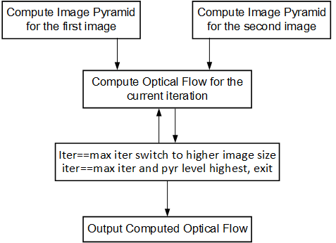
The Iterative Pyramidal Dense Optical Flow is computed in a nested for loop which runs for iterations*pyramid levels number of iterations. The main loop starts from the smallest image size and iterates up to the largest image size. Before the loop iterates in one pyramid level, it sets the current pyramid level’s height and width, in curr_height and current_width variables. In the nested loop, the next_height variable is set to the previous image height if scaling up is necessary, that is, in the first iterations. As divisions are costly and one time divisions can be avoided in hardware, the scale factor is computed in the host and passed as an argument to the hardware kernel. After each pyramid level, in the first iteration, the scale-up flag is set to let the hardware function know that the input flow vectors need to be scaled up to the next higher image size. Scaling up is done using bilinear interpolation in the hardware kernel.
After all the input data is prepared, and the flags are set, the host processor calls the hardware function. Please note that the host function swaps the flow vector inputs and outputs to the hardware function to iteratively solve the optimization problem.
Corner Tracking Using Optical Flow
This example illustrates how to detect and track the characteristic feature points in a set of successive frames of video. A Harris corner detector is used as the feature detector, and a modified version of Lucas Kanade optical flow is used for tracking. The core part of the algorithm takes in current and next frame as the inputs and outputs the list of tracked corners. The current image is the first frame in the set, then corner detection is performed to detect the features to track. The number of frames in which the points need to be tracked is also provided as the input.
Corner tracking example uses five hardware functions from the Vitis vision
library xf::cv::cornerHarris, xf::cv:: cornersImgToList,
xf::cv::cornerUpdate, xf::cv::pyrDown, and xf::cv::densePyrOpticalFlow.
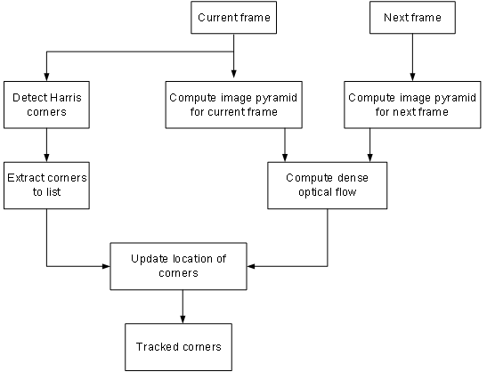
The function, xf::cv::cornerUpdate, has been added to ensure
that the dense flow vectors from the output of
thexf::cv::densePyrOpticalFlow function are sparsely picked and stored
in a new memory location as a sparse array. This was done to ensure that
the next function in the pipeline would not have to surf through the
memory by random accesses. The function takes corners from Harris corner
detector and dense optical flow vectors from the dense pyramidal optical
flow function and outputs the updated corner locations, tracking the
input corners using the dense flow vectors, thereby imitating the sparse
optical flow behavior. This hardware function runs at 300 MHz for 10,000
corners on a 720p image, adding very minimal latency to the pipeline.
cornerUpdate()
API Syntax
template <unsigned int MAXCORNERSNO, unsigned int TYPE, unsigned int ROWS, unsigned int COLS, unsigned int NPC>
void cornerUpdate(ap_uint<64> *list_fix, unsigned int *list, uint32_t nCorners, xf::cv::Mat<TYPE,ROWS,COLS,NPC> &flow_vectors, ap_uint<1> harris_flag)
Parameter Descriptions
The following table describes the template and the function parameters.
| Paramete r | Description |
|---|---|
| MAXCORNE RSNO | Maximum number of corners that the function needs to work on |
| TYPE | Input Pixel Type. Only 8-bit, unsigned, 1 channel is supported (XF_8UC1) |
| ROWS | Maximum height of input and output image (Must be multiple of 8) |
| COLS | Maximum width of input and output image (Must be multiple of 8) |
| NPC | Number of pixels to be processed per cycle. This function supports only XF_NPPC1 or 1-pixel per cycle operations. |
| list_fix | A list of packed fixed point coordinates of the corner locations in 16, 5 (16 integer bits and 5 fractional bits) format. Bits from 20 to 0 represent the column number, while the bits 41 to 21 represent the row number. The rest of the bits are used for flag, this flag is set when the tracked corner is valid. |
| list | A list of packed positive short integer coordinates of the corner locations in unsigned short format. Bits from 15 to 0 represent the column number, while the bits 31 to 16 represent the row number. This list is same as the list output by Harris Corner Detector. |
| nCorners | Number of corners to track |
| flow_vec tors | Packed flow vectors as in xf::cv::DensePyrOpticalFlow function |
| harris_f lag | If set to 1, the function takes input corners from list. if set to 0, the function takes input corners from list_fix. |
The example codeworks on an input video which is read and processed using the Vitis vision library.
cornersImgToList()
API Syntax
template <unsigned int MAXCORNERSNO, unsigned int TYPE, unsigned int ROWS, unsigned int COLS, unsigned int NPC>
void cornersImgToList(xf::cv::Mat<TYPE,ROWS,COLS,NPC> &_src, unsigned int list[MAXCORNERSNO], unsigned int *ncorners)
Parameter Descriptions
The following table describes the function parameters.
| Paramete r | Description |
|---|---|
| _src | The output image of harris corner detector. The size of this xf::cv::Mat object is the size of the input image to Harris corner detector. The value of each pixel is 255 if a corner is present in the location, 0 otherwise. |
| list | A 32 bit memory allocated, the size of MAXCORNERS, to store the corners detected by Harris Detector |
| ncorners | Total number of corners detected by Harris, that is, the number of corners in the list |
Image Processing
The following steps demonstrate the Image Processing procedure in the hardware pipeline
xf::cv::cornerharrisis called to start processing the first input image- The output of
xf::cv::cornerHarrisis fed toxf::cv::cornersImgToList. This function takes in an image with corners (marked as 255 and 0 elsewhere), and converts them to a list of corners. xf::cv::pyrDowncreates the two image pyramids and Dense Optical Flow is computed using the two image pyramids as described in the Iterative Pyramidal Dense Optical Flow example.xf::cv::densePyrOpticalFlowis called with the two image pyramids as inputs.xf::cv::cornerUpdatefunction is called to track the corner locations in the second image. If harris_flag is enabled, thecornerUpdatetracks corners from the output of the list, else it tracks the previously tracked corners.
The HarrisImg() function takes a flag called
harris_flag which is set during the first frame or when the corners need
to be redetected. The xf::cv::cornerUpdate function outputs the updated
corners to the same memory location as the output corners list of
xf::cv::cornerImgToList. This means that when harris_flag is unset, the
corners input to the xf::cv::cornerUpdate are the corners tracked in the
previous cycle, that is, the corners in the first frame of the current
input frames.
After the Dense Optical Flow is computed, if harris_flag is set, the
number of corners that xf::cv::cornerharris has detected and
xf::cv::cornersImgToList has updated is copied to num_corners variable
. The other being the tracked corners list, listfixed. If
harris_flag is set, xf::cv::cornerUpdate tracks the corners in ‘list’
memory location, otherwise it tracks the corners in ‘listfixed’ memory
location.
Color Detection
The Color Detection algorithm is basically used for color object tracking and object detection, based on the color of the object. The color based methods are very useful for object detection and segmentation, when the object and the background have a significant difference in color.
The Color Detection example uses four hardware functions from the Vitis vision library. They are:
- xf::cv::BGR2HSV
- xf::cv::colorthresholding
- xf::cv::erode
- xf::cv::dilate
In the Color Detection example, the color space of the original BGR image is converted into an HSV color space. Because HSV color space is the most suitable color space for color based image segmentation. Later, based on the H (hue), S (saturation) and V (value) values, apply the thresholding operation on the HSV image and return either 255 or 0. After thresholding the image, apply erode (morphological opening) and dilate (morphological opening) functions to reduce unnecessary white patches (noise) in the image. Here, the example uses two hardware instances of erode and dilate functions. The erode followed by dilate and once again applying dilate followed by erode.
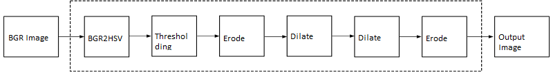
The following example demonstrates the Color Detection algorithm.
    void color_detect(ap_uint<PTR_IN_WIDTH>* img_in,
              unsigned char* low_thresh,
              unsigned char* high_thresh,
              unsigned char* process_shape,
              ap_uint<PTR_OUT_WIDTH>* img_out,
              int rows,
              int cols) {

#pragma HLS INTERFACE m_axi      port=img_in        offset=slave  bundle=gmem0
#pragma HLS INTERFACE m_axi      port=low_thresh    offset=slave  bundle=gmem1
#pragma HLS INTERFACE s_axilite  port=low_thresh
#pragma HLS INTERFACE m_axi      port=high_thresh   offset=slave  bundle=gmem2
#pragma HLS INTERFACE s_axilite  port=high_thresh
#pragma HLS INTERFACE s_axilite  port=rows
#pragma HLS INTERFACE s_axilite  port=cols
#pragma HLS INTERFACE m_axi      port=process_shape offset=slave  bundle=gmem3
#pragma HLS INTERFACE s_axilite  port=process_shape
#pragma HLS INTERFACE m_axi      port=img_out       offset=slave  bundle=gmem4
#pragma HLS INTERFACE s_axilite  port=return

            xf::cv::Mat<IN_TYPE, HEIGHT, WIDTH, NPC1> imgInput(rows, cols);
            xf::cv::Mat<IN_TYPE, HEIGHT, WIDTH, NPC1> rgb2hsv(rows, cols);
            xf::cv::Mat<OUT_TYPE, HEIGHT, WIDTH, NPC1> imgHelper1(rows, cols);
            xf::cv::Mat<OUT_TYPE, HEIGHT, WIDTH, NPC1> imgHelper2(rows, cols);
            xf::cv::Mat<OUT_TYPE, HEIGHT, WIDTH, NPC1> imgHelper3(rows, cols);
            xf::cv::Mat<OUT_TYPE, HEIGHT, WIDTH, NPC1> imgHelper4(rows, cols);
            xf::cv::Mat<OUT_TYPE, HEIGHT, WIDTH, NPC1> imgOutput(rows, cols);

            // Copy the shape data:
            unsigned char _kernel[FILTER_SIZE * FILTER_SIZE];
            for (unsigned int i = 0; i < FILTER_SIZE * FILTER_SIZE; ++i) {

                    #pragma HLS PIPELINE
                    // clang-format on
                    _kernel[i] = process_shape[i];
            }

    #pragma HLS DATAFLOW
            // clang-format on
            // Retrieve xf::cv::Mat objects from img_in data:
            xf::cv::Array2xfMat<PTR_IN_WIDTH, IN_TYPE, HEIGHT, WIDTH, NPC1>(img_in, imgInput);

            // Convert RGBA to HSV:
            xf::cv::bgr2hsv<IN_TYPE, HEIGHT, WIDTH, NPC1>(imgInput, rgb2hsv);

            // Do the color thresholding:
            xf::cv::colorthresholding<IN_TYPE, OUT_TYPE, MAXCOLORS, HEIGHT, WIDTH, NPC1>(rgb2hsv, imgHelper1, low_thresh,
                                                                                                                                                                     high_thresh);

            // Use erode and dilate to fully mark color areas:
            xf::cv::erode<XF_BORDER_CONSTANT, OUT_TYPE, HEIGHT, WIDTH, XF_KERNEL_SHAPE, FILTER_SIZE, FILTER_SIZE, ITERATIONS,
                                      NPC1>(imgHelper1, imgHelper2, _kernel);
            xf::cv::dilate<XF_BORDER_CONSTANT, OUT_TYPE, HEIGHT, WIDTH, XF_KERNEL_SHAPE, FILTER_SIZE, FILTER_SIZE, ITERATIONS,
                                       NPC1>(imgHelper2, imgHelper3, _kernel);
            xf::cv::dilate<XF_BORDER_CONSTANT, OUT_TYPE, HEIGHT, WIDTH, XF_KERNEL_SHAPE, FILTER_SIZE, FILTER_SIZE, ITERATIONS,
                                       NPC1>(imgHelper3, imgHelper4, _kernel);
            xf::cv::erode<XF_BORDER_CONSTANT, OUT_TYPE, HEIGHT, WIDTH, XF_KERNEL_SHAPE, FILTER_SIZE, FILTER_SIZE, ITERATIONS,
                                      NPC1>(imgHelper4, imgOutput, _kernel);

            // Convert _dst xf::cv::Mat object to output array:
            xf::cv::xfMat2Array<PTR_OUT_WIDTH, OUT_TYPE, HEIGHT, WIDTH, NPC1>(imgOutput, img_out);

            return;

    } // End of kernel
In the given example, the source image is passed to the xf::cv::BGR2HSV
function, the output of that function is passed to the
xf::cv::colorthresholding module, the thresholded image is passed to the
xf::cv::erode function and, the xf::cv::dilate functions and the final
output image are returned.
Difference of Gaussian Filter
The Difference of Gaussian Filter example uses four hardware functions from the Vitis vision library. They are:
- xf::cv::GaussianBlur
- xf::cv::duplicateMat
- xf::cv::subtract
The Difference of Gaussian Filter function can be implemented by applying Gaussian Filter on the original source image, and that Gaussian blurred image is duplicated as two images. The Gaussian blur function is applied to one of the duplicated images, whereas the other one is stored as it is. Later, perform the Subtraction function on, two times Gaussian applied image and one of the duplicated image.
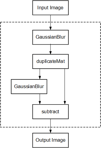
The following example demonstrates the Difference of Gaussian Filter example.
    void gaussiandiference(ap_uint<PTR_WIDTH>* img_in, float sigma, ap_uint<PTR_WIDTH>* img_out, int rows, int cols) {

#pragma HLS INTERFACE m_axi      port=img_in        offset=slave  bundle=gmem0
#pragma HLS INTERFACE m_axi      port=img_out       offset=slave  bundle=gmem1
#pragma HLS INTERFACE s_axilite  port=sigma
    #pragma HLS INTERFACE s_axilite  port=rows
    #pragma HLS INTERFACE s_axilite  port=cols
#pragma HLS INTERFACE s_axilite  port=return

            xf::cv::Mat<TYPE, HEIGHT, WIDTH, NPC1> imgInput(rows, cols);
            xf::cv::Mat<TYPE, HEIGHT, WIDTH, NPC1> imgin1(rows, cols);
            xf::cv::Mat<TYPE, HEIGHT, WIDTH, NPC1> imgin2(rows, cols);
            xf::cv::Mat<TYPE, HEIGHT, WIDTH, NPC1, 15360> imgin3(rows, cols);
            xf::cv::Mat<TYPE, HEIGHT, WIDTH, NPC1> imgin4(rows, cols);
            xf::cv::Mat<TYPE, HEIGHT, WIDTH, NPC1> imgOutput(rows, cols);

    #pragma HLS DATAFLOW

            // Retrieve xf::cv::Mat objects from img_in data:
            xf::cv::Array2xfMat<PTR_WIDTH, TYPE, HEIGHT, WIDTH, NPC1>(img_in, imgInput);

            // Run xfOpenCV kernel:
            xf::cv::GaussianBlur<FILTER_WIDTH, XF_BORDER_CONSTANT, TYPE, HEIGHT, WIDTH, NPC1>(imgInput, imgin1, sigma);
            xf::cv::duplicateMat<TYPE, HEIGHT, WIDTH, NPC1, 15360>(imgin1, imgin2, imgin3);
            xf::cv::GaussianBlur<FILTER_WIDTH, XF_BORDER_CONSTANT, TYPE, HEIGHT, WIDTH, NPC1>(imgin2, imgin4, sigma);
            xf::cv::subtract<XF_CONVERT_POLICY_SATURATE, TYPE, HEIGHT, WIDTH, NPC1, 15360>(imgin3, imgin4, imgOutput);

            // Convert output xf::cv::Mat object to output array:
            xf::cv::xfMat2Array<PTR_WIDTH, TYPE, HEIGHT, WIDTH, NPC1>(imgOutput, img_out);

            return;
    } // End of kernel
In the given example, the Gaussain Blur function is applied for source image imginput, and resultant image imgin1 is passed to xf::cv::duplicateMat. The imgin2 and imgin3 are the duplicate images of Gaussian applied image. Again gaussian blur is applied to imgin2 and the result is stored in imgin4. Now, perform the subtraction between imgin4 and imgin3, but here imgin3 has to wait up to at least one pixel of imgin4 generation. Finally the subtraction performed on imgin3 and imgin4.
Stereo Vision Pipeline
Disparity map generation is one of the first steps in creating a three dimensional map of the environment. The Vitis vision library has components to build an image processing pipeline to compute a disparity map given the camera parameters and inputs from a stereo camera setup.
The two main components involved in the pipeline are stereo
rectification and disparity estimation using local block matching
method. While disparity estimation using local block matching is a
discrete component in Vitis vision, rectification block can be constructed
using xf::cv::InitUndistortRectifyMapInverse() and xf::cv::Remap(). The
dataflow pipeline is shown below. The camera parameters are an
additional input to the pipeline.
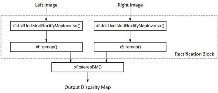
The following code is for the pipeline.
    void stereopipeline_accel(ap_uint<INPUT_PTR_WIDTH>* img_L,
                      ap_uint<INPUT_PTR_WIDTH>* img_R,
                      ap_uint<OUTPUT_PTR_WIDTH>* img_disp,
                      float* cameraMA_l,
                      float* cameraMA_r,
                      float* distC_l,
                      float* distC_r,
                      float* irA_l,
                      float* irA_r,
                      int* bm_state_arr,
                      int rows,
                      int cols) {

#pragma HLS INTERFACE m_axi     port=img_L  offset=slave bundle=gmem1
#pragma HLS INTERFACE m_axi     port=img_R  offset=slave bundle=gmem5
#pragma HLS INTERFACE m_axi     port=img_disp  offset=slave bundle=gmem6
#pragma HLS INTERFACE m_axi     port=cameraMA_l  offset=slave bundle=gmem2
#pragma HLS INTERFACE m_axi     port=cameraMA_r  offset=slave bundle=gmem2
#pragma HLS INTERFACE m_axi     port=distC_l  offset=slave bundle=gmem3
#pragma HLS INTERFACE m_axi     port=distC_r  offset=slave bundle=gmem3
#pragma HLS INTERFACE m_axi     port=irA_l  offset=slave bundle=gmem2
#pragma HLS INTERFACE m_axi     port=irA_r  offset=slave bundle=gmem2
#pragma HLS INTERFACE m_axi     port=bm_state_arr  offset=slave bundle=gmem4
#pragma HLS INTERFACE s_axilite port=rows
#pragma HLS INTERFACE s_axilite port=cols
#pragma HLS INTERFACE s_axilite port=return

            ap_fixed<32, 12> cameraMA_l_fix[XF_CAMERA_MATRIX_SIZE], cameraMA_r_fix[XF_CAMERA_MATRIX_SIZE],
                    distC_l_fix[XF_DIST_COEFF_SIZE], distC_r_fix[XF_DIST_COEFF_SIZE], irA_l_fix[XF_CAMERA_MATRIX_SIZE],
                    irA_r_fix[XF_CAMERA_MATRIX_SIZE];

            for (int i = 0; i < XF_CAMERA_MATRIX_SIZE; i++) {

                    #pragma HLS PIPELINE II=1
                    // clang-format on
                    cameraMA_l_fix[i] = (ap_fixed<32, 12>)cameraMA_l[i];
                    cameraMA_r_fix[i] = (ap_fixed<32, 12>)cameraMA_r[i];
                    irA_l_fix[i] = (ap_fixed<32, 12>)irA_l[i];
                    irA_r_fix[i] = (ap_fixed<32, 12>)irA_r[i];
            }
            for (int i = 0; i < XF_DIST_COEFF_SIZE; i++) {

                    #pragma HLS PIPELINE II=1
                    // clang-format on
                    distC_l_fix[i] = (ap_fixed<32, 12>)distC_l[i];
                    distC_r_fix[i] = (ap_fixed<32, 12>)distC_r[i];
            }

            xf::cv::xFSBMState<SAD_WINDOW_SIZE, NO_OF_DISPARITIES, PARALLEL_UNITS> bm_state;
            bm_state.preFilterType = bm_state_arr[0];
            bm_state.preFilterSize = bm_state_arr[1];
            bm_state.preFilterCap = bm_state_arr[2];
            bm_state.SADWindowSize = bm_state_arr[3];
            bm_state.minDisparity = bm_state_arr[4];
            bm_state.numberOfDisparities = bm_state_arr[5];
            bm_state.textureThreshold = bm_state_arr[6];
            bm_state.uniquenessRatio = bm_state_arr[7];
            bm_state.ndisp_unit = bm_state_arr[8];
            bm_state.sweepFactor = bm_state_arr[9];
            bm_state.remainder = bm_state_arr[10];

            int _cm_size = 9, _dc_size = 5;

            xf::cv::Mat<XF_8UC1, XF_HEIGHT, XF_WIDTH, XF_NPPC1> mat_L(rows, cols);

            xf::cv::Mat<XF_8UC1, XF_HEIGHT, XF_WIDTH, XF_NPPC1> mat_R(rows, cols);

            xf::cv::Mat<XF_16UC1, XF_HEIGHT, XF_WIDTH, XF_NPPC1> mat_disp(rows, cols);

            xf::cv::Mat<XF_32FC1, XF_HEIGHT, XF_WIDTH, XF_NPPC1> mapxLMat(rows, cols);

            xf::cv::Mat<XF_32FC1, XF_HEIGHT, XF_WIDTH, XF_NPPC1> mapyLMat(rows, cols);

            xf::cv::Mat<XF_32FC1, XF_HEIGHT, XF_WIDTH, XF_NPPC1> mapxRMat(rows, cols);

            xf::cv::Mat<XF_32FC1, XF_HEIGHT, XF_WIDTH, XF_NPPC1> mapyRMat(rows, cols);

            xf::cv::Mat<XF_8UC1, XF_HEIGHT, XF_WIDTH, XF_NPPC1> leftRemappedMat(rows, cols);

            xf::cv::Mat<XF_8UC1, XF_HEIGHT, XF_WIDTH, XF_NPPC1> rightRemappedMat(rows, cols);


    #pragma HLS DATAFLOW

            xf::cv::Array2xfMat<INPUT_PTR_WIDTH, XF_8UC1, XF_HEIGHT, XF_WIDTH, XF_NPPC1>(img_L, mat_L);
            xf::cv::Array2xfMat<INPUT_PTR_WIDTH, XF_8UC1, XF_HEIGHT, XF_WIDTH, XF_NPPC1>(img_R, mat_R);

            xf::cv::InitUndistortRectifyMapInverse<XF_CAMERA_MATRIX_SIZE, XF_DIST_COEFF_SIZE, XF_32FC1, XF_HEIGHT, XF_WIDTH,
                                                                                       XF_NPPC1>(cameraMA_l_fix, distC_l_fix, irA_l_fix, mapxLMat, mapyLMat,
                                                                                                             _cm_size, _dc_size);
            xf::cv::remap<XF_REMAP_BUFSIZE, XF_INTERPOLATION_BILINEAR, XF_8UC1, XF_32FC1, XF_8UC1, XF_HEIGHT, XF_WIDTH,
                                      XF_NPPC1, XF_USE_URAM>(mat_L, leftRemappedMat, mapxLMat, mapyLMat);

            xf::cv::InitUndistortRectifyMapInverse<XF_CAMERA_MATRIX_SIZE, XF_DIST_COEFF_SIZE, XF_32FC1, XF_HEIGHT, XF_WIDTH,
                                                                                       XF_NPPC1>(cameraMA_r_fix, distC_r_fix, irA_r_fix, mapxRMat, mapyRMat,
                                                                                                             _cm_size, _dc_size);
            xf::cv::remap<XF_REMAP_BUFSIZE, XF_INTERPOLATION_BILINEAR, XF_8UC1, XF_32FC1, XF_8UC1, XF_HEIGHT, XF_WIDTH,
                                      XF_NPPC1, XF_USE_URAM>(mat_R, rightRemappedMat, mapxRMat, mapyRMat);

            xf::cv::StereoBM<SAD_WINDOW_SIZE, NO_OF_DISPARITIES, PARALLEL_UNITS, XF_8UC1, XF_16UC1, XF_HEIGHT, XF_WIDTH,
                                             XF_NPPC1, XF_USE_URAM>(leftRemappedMat, rightRemappedMat, mat_disp, bm_state);

            xf::cv::xfMat2Array<OUTPUT_PTR_WIDTH, XF_16UC1, XF_HEIGHT, XF_WIDTH, XF_NPPC1>(mat_disp, img_disp);
    }
Blob From Image
This example shows how various xfOpenCV funtions can be used to accelerate preprocessing of input images before feeding them to a Deep Neural Network (DNN) accelerator.
This specific application shows how pre-processing for Googlenet_v1 can be accelerated which involves resizing the input image to 224 x 224 size followed by mean subtraction. The two main
functions from Vitis vision library which are used to build this pipeline are xf::cv::resize() and xf::cv::preProcess() which operate in dataflow.
The following code shows the top level wrapper containing the xf::cv::resize() and xf::cv::preProcess() calls.
void pp_pipeline_accel(ap_uint<INPUT_PTR_WIDTH> *img_inp, ap_uint<OUTPUT_PTR_WIDTH> *img_out, int rows_in, int cols_in, int rows_out, int cols_out, float params[3*T_CHANNELS], int th1, int th2)
{
//HLS Interface pragmas
#pragma HLS INTERFACE m_axi     port=img_inp  offset=slave bundle=gmem1
#pragma HLS INTERFACE m_axi     port=img_out  offset=slave bundle=gmem2
#pragma HLS INTERFACE m_axi     port=params  offset=slave bundle=gmem3

#pragma HLS INTERFACE s_axilite port=rows_in     bundle=control
#pragma HLS INTERFACE s_axilite port=cols_in     bundle=control
#pragma HLS INTERFACE s_axilite port=rows_out     bundle=control
#pragma HLS INTERFACE s_axilite port=cols_out     bundle=control
#pragma HLS INTERFACE s_axilite port=th1     bundle=control
#pragma HLS INTERFACE s_axilite port=th2     bundle=control

#pragma HLS INTERFACE s_axilite port=return   bundle=control

            xf::cv::Mat<XF_8UC3, HEIGHT, WIDTH, NPC1>   imgInput0(rows_in, cols_in);
            xf::cv::Mat<TYPE, NEWHEIGHT, NEWWIDTH, NPC_T> out_mat(rows_out, cols_out);

    hls::stream<ap_uint<256> > resizeStrmout;
    int srcMat_cols_align_npc = ((out_mat.cols + (NPC_T - 1)) >> XF_BITSHIFT(NPC_T)) << XF_BITSHIFT(NPC_T);

    #pragma HLS DATAFLOW

    xf::cv::Array2xfMat<INPUT_PTR_WIDTH,XF_8UC3,HEIGHT, WIDTH, NPC1>  (img_inp, imgInput0);
    xf::cv::resize<INTERPOLATION,TYPE,HEIGHT,WIDTH,NEWHEIGHT,NEWWIDTH,NPC_T,MAXDOWNSCALE> (imgInput0, out_mat);
    xf::cv::accel_utils obj;
    obj.xfMat2hlsStrm<INPUT_PTR_WIDTH, TYPE, NEWHEIGHT, NEWWIDTH, NPC_T, (NEWWIDTH*NEWHEIGHT/8)>(out_mat, resizeStrmout, srcMat_cols_align_npc);
    xf::cv::preProcess <INPUT_PTR_WIDTH, OUTPUT_PTR_WIDTH, T_CHANNELS, CPW, HEIGHT, WIDTH, NPC_TEST, PACK_MODE, X_WIDTH, ALPHA_WIDTH, BETA_WIDTH, GAMMA_WIDTH, OUT_WIDTH, X_IBITS, ALPHA_IBITS, BETA_IBITS, GAMMA_IBITS, OUT_IBITS, SIGNED_IN, OPMODE> (resizeStrmout, img_out, params, rows_out, cols_out, th1, th2);

}
This piepeline is integrated with Deep learning Processign Unit(DPU) as part of Vitis-AI-Library and achieved 11 % speed up compared to software pre-procesing.
- Overall Performance (Images/sec):
- with software pre-processing : 125 images/sec
- with hardware accelerated pre-processing : 140 images/sec
Letterbox
The Letterbox algorithm is used for scaling input image to desired output size while preserving aspect ratio of original image. If required, zeroes are padded for preserving the aspect ratio post resize.
An application of letterbox is in the pre-processing block of machine learning pipelines used in image processing.
The following example demonstrates the Letterbox algorithm.
void letterbox_accel(ap_uint<INPUT_PTR_WIDTH>* img_inp,
                    ap_uint<OUTPUT_PTR_WIDTH>* img_out,
                    int rows_in,
                    int cols_in,
                    int rows_out,
                    int cols_out,
                    int insert_pad_value) {

            #pragma HLS INTERFACE m_axi     port=img_inp  offset=slave bundle=gmem1
            #pragma HLS INTERFACE m_axi     port=img_out  offset=slave bundle=gmem2
            #pragma HLS INTERFACE s_axilite port=rows_in
            #pragma HLS INTERFACE s_axilite port=cols_in
            #pragma HLS INTERFACE s_axilite port=rows_out
            #pragma HLS INTERFACE s_axilite port=cols_out
            #pragma HLS INTERFACE s_axilite port=insert_pad_value
            #pragma HLS INTERFACE s_axilite port=return


                    // Compute Resize output image size for Letterbox
                    float scale_height = (float)rows_out/(float)rows_in;
                    float scale_width = (float)cols_out/(float)cols_in;
                    int rows_out_resize, cols_out_resize;
                    if(scale_width<scale_height){
                            cols_out_resize = cols_out;
                            rows_out_resize = (int)((float)(rows_in*cols_out)/(float)cols_in);
                    }
                    else{
                            cols_out_resize = (int)((float)(cols_in*rows_out)/(float)rows_in);
                            rows_out_resize = rows_out;
                    }

                    xf::cv::Mat<TYPE, HEIGHT, WIDTH, NPC_T> imgInput0(rows_in, cols_in);
                    xf::cv::Mat<TYPE, NEWHEIGHT, NEWWIDTH, NPC_T> out_mat_resize(rows_out_resize, cols_out_resize);
                    xf::cv::Mat<TYPE, NEWHEIGHT, NEWWIDTH, NPC_T> out_mat(rows_out, cols_out);

            #pragma HLS DATAFLOW

                    xf::cv::Array2xfMat<INPUT_PTR_WIDTH,XF_8UC3,HEIGHT, WIDTH, NPC_T>  (img_inp, imgInput0);
                    xf::cv::resize<INTERPOLATION,TYPE,HEIGHT,WIDTH,NEWHEIGHT,NEWWIDTH,NPC_T,MAXDOWNSCALE> (imgInput0, out_mat_resize);
                    xf::cv::insertBorder<TYPE, NEWHEIGHT, NEWWIDTH, NEWHEIGHT, NEWWIDTH, NPC_T>(out_mat_resize, out_mat, insert_pad_value);
                    xf::cv::xfMat2Array<OUTPUT_PTR_WIDTH, TYPE, NEWHEIGHT, NEWWIDTH, NPC_T>(out_mat, img_out);
                    return;
                    }// end kernel
The Letterbox example uses two hardware functions from the Vitis vision library. They are:
- xf::cv::resize
- xf::cv::insertBorder
In the given example, the source image is passed to the xf::cv::resize function. The output of that function is passed to the xf::cv::insertBorder module and the final output image are returned.
Insert Border API Syntax
template <
    int TYPE,
    int SRC_ROWS,
    int SRC_COLS,
    int DST_ROWS,
    int DST_COLS,
    int NPC
    >
void insertBorder (
    xf::cv::Mat <TYPE, SRC_ROWS, SRC_COLS, NPC>& _src,
    xf::cv::Mat <TYPE, DST_ROWS, DST_COLS, NPC>& _dst,
    int insert_pad_val
    )
Image Sensor Processing pipeline
Image Sensor Processing (ISP) is a pipeline of image processing functions processing the raw image from the sensor.
Current ISP includes following 4 blocks:
- BPC (Bad pixel correction) : An image sensor may have a certain number of defective/bad pixels that may be the result of manufacturing faults or variations in pixel voltage levels based on temperature or exposure. Bad pixel correction module removes defective pixels.
- Gain Control : The Gain control module improves the overall brightness of the image.
- Demosaicing : The demosaic module reconstructs RGB pixels from the input Bayer image (RGGB,BGGR,RGBG,GRGB).
- Auto white balance: The AWB module improves color balance of the image by using image statistics.
Current design example demonstrates how to use ISP functions in a pipeline. User can include other modules (like gamma correction, color conversion, resize etc) based on their need.
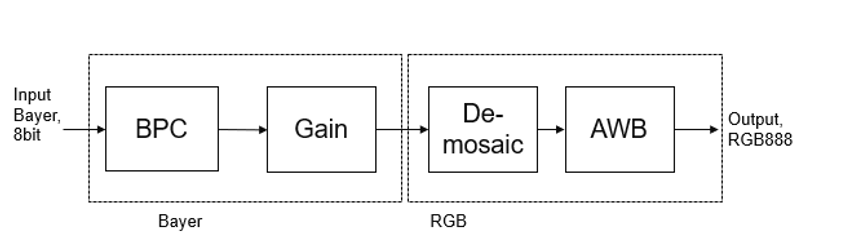
The following example demonstrates the ISP pipeline.
void ISPPipeline_accel(ap_uint<INPUT_PTR_WIDTH>* img_inp, ap_uint<OUTPUT_PTR_WIDTH>* img_out, int height, int width) {

#pragma HLS INTERFACE m_axi     port=img_inp  offset=slave bundle=gmem1
#pragma HLS INTERFACE m_axi     port=img_out  offset=slave bundle=gmem2
#pragma HLS INTERFACE s_axilite port=height
#pragma HLS INTERFACE s_axilite port=width
#pragma HLS INTERFACE s_axilite port=return
#pragma HLS ARRAY_PARTITION variable=hist0 complete dim=1
#pragma HLS ARRAY_PARTITION variable=hist1 complete dim=1

        if (!flag) {
                ISPpipeline(img_inp, img_out, height, width, hist0, hist1);
                flag = 1;
        } else {
                ISPpipeline(img_inp, img_out, height, width, hist1, hist0);
                flag = 0;
        }
}
void ISPpipeline(ap_uint<INPUT_PTR_WIDTH>* img_inp,
                                 ap_uint<OUTPUT_PTR_WIDTH>* img_out,
                                 int height,
                                 int width,
                                 uint32_t hist0[3][256],
                                 uint32_t hist1[3][256]) {
#pragma HLS INLINE OFF
        xf::cv::Mat<XF_SRC_T, XF_HEIGHT, XF_WIDTH, XF_NPPC> imgInput1(height, width);
        xf::cv::Mat<XF_SRC_T, XF_HEIGHT, XF_WIDTH, XF_NPPC> bpc_out(height, width);
        xf::cv::Mat<XF_SRC_T, XF_HEIGHT, XF_WIDTH, XF_NPPC> gain_out(height, width);
        xf::cv::Mat<XF_DST_T, XF_HEIGHT, XF_WIDTH, XF_NPPC> demosaic_out(height, width);
        xf::cv::Mat<XF_DST_T, XF_HEIGHT, XF_WIDTH, XF_NPPC> impop(height, width);
        xf::cv::Mat<XF_DST_T, XF_HEIGHT, XF_WIDTH, XF_NPPC> _dst(height, width);

#pragma HLS stream variable=bpc_out.data dim=1 depth=2
#pragma HLS stream variable=gain_out.data dim=1 depth=2
#pragma HLS stream variable=demosaic_out.data dim=1 depth=2
#pragma HLS stream variable=imgInput1.data dim=1 depth=2
#pragma HLS stream variable=impop.data dim=1 depth=2
#pragma HLS stream variable=_dst.data dim=1 depth=2

#pragma HLS DATAFLOW


        float inputMin = 0.0f;
        float inputMax = 255.0f;
        float outputMin = 0.0f;
        float outputMax = 255.0f;
        float p = 2.0f;

        xf::cv::Array2xfMat<INPUT_PTR_WIDTH, XF_SRC_T, XF_HEIGHT, XF_WIDTH, XF_NPPC>(img_inp, imgInput1);
        xf::cv::badpixelcorrection<XF_SRC_T, XF_HEIGHT, XF_WIDTH, XF_NPPC, 0, 0>(imgInput1, bpc_out);
        xf::cv::gaincontrol<XF_BAYER_PATTERN, XF_SRC_T, XF_HEIGHT, XF_WIDTH, XF_NPPC>(bpc_out, gain_out);
        xf::cv::demosaicing<XF_BAYER_PATTERN, XF_SRC_T, XF_DST_T, XF_HEIGHT, XF_WIDTH, XF_NPPC, 0>(gain_out, demosaic_out);
        xf::cv::AWBhistogram<XF_DST_T, XF_DST_T, XF_HEIGHT, XF_WIDTH, XF_NPPC, WB_TYPE>(
                demosaic_out, impop, hist0, p, inputMin, inputMax, outputMin, outputMax);
        xf::cv::AWBNormalization<XF_DST_T, XF_DST_T, XF_HEIGHT, XF_WIDTH, XF_NPPC, WB_TYPE>(impop, _dst, hist1, p, inputMin,
                                                                                                                                                                                inputMax, outputMin, outputMax);
        xf::cv::xfMat2Array<OUTPUT_PTR_WIDTH, XF_DST_T, XF_HEIGHT, XF_WIDTH, XF_NPPC>(_dst, img_out);
}
Image Sensor Processing pipeline - 2020.2 version
This ISP includes following 8 blocks:
- Black level correction : Black level leads to the whitening of image in dark region and perceived loss of overall contrast. The Blacklevelcorrection algorithm corrects the black and white levels of the overall image.
- BPC (Bad pixel correction) : An image sensor may have a certain number of defective/bad pixels that may be the result of manufacturing faults or variations in pixel voltage levels based on temperature or exposure. Bad pixel correction module removes defective pixels.
- Gain Control : The Gain control module improves the overall brightness of the image.
- Demosaicing : The demosaic module reconstructs RGB pixels from the input Bayer image (RGGB,BGGR,RGBG,GRGB).
- Auto white balance: The AWB module improves color balance of the image by using image statistics.
- Colorcorrection matrix : corrects color suitable for display or video system.
- Quantization and Dithering : Quantization and Dithering performs the uniform quantization to also reduce higher bit depth to lower bit depths.
- Autoexposurecorrection : This function automatically attempts to correct the exposure level of captured image and also improves contrast of the image.
Current design example demonstrates how to use ISP functions in a pipeline. User can include other modules (like gamma correction, color conversion, resize etc) based on their need.
The following example demonstrates the ISP pipeline with above list of functions.
void ISPPipeline_accel(ap_uint<INPUT_PTR_WIDTH>* img_inp, ap_uint<OUTPUT_PTR_WIDTH>* img_out, int height, int width) {

#pragma HLS INTERFACE m_axi     port=img_inp  offset=slave bundle=gmem1
#pragma HLS INTERFACE m_axi     port=img_out  offset=slave bundle=gmem2

#pragma HLS ARRAY_PARTITION variable=hist0 complete dim=1
#pragma HLS ARRAY_PARTITION variable=hist1 complete dim=1

        if (!flag) {
                ISPpipeline(img_inp, img_out, height, width, hist0, hist1, histogram0, histogram1, igain_0, igain_1);
                flag = 1;

        } else {
                ISPpipeline(img_inp, img_out, height, width, hist1, hist0, histogram1, histogram0, igain_1, igain_0);
                flag = 0;
        }
}

void ISPpipeline(ap_uint<INPUT_PTR_WIDTH>* img_inp,
                                ap_uint<OUTPUT_PTR_WIDTH>* img_out,
                                unsigned short height,
                                unsigned short width,
                                uint32_t hist0[3][HIST_SIZE],
                                uint32_t hist1[3][HIST_SIZE],
                                uint32_t hist_aec1[1][256],
                                uint32_t hist_aec2[1][256],
                                int gain0[3], int gain1[3]) {

        #pragma HLS INLINE OFF

                xf::cv::Mat<XF_SRC_T, XF_HEIGHT, XF_WIDTH, XF_NPPC> imgInput1(height, width);
                xf::cv::Mat<XF_SRC_T, XF_HEIGHT, XF_WIDTH, XF_NPPC> imgInput2(height, width);
                xf::cv::Mat<XF_SRC_T, XF_HEIGHT, XF_WIDTH, XF_NPPC> bpc_out(height, width);
                xf::cv::Mat<XF_SRC_T, XF_HEIGHT, XF_WIDTH, XF_NPPC> gain_out(height, width);
                xf::cv::Mat<XF_DST_T, XF_HEIGHT, XF_WIDTH, XF_NPPC> demosaic_out(height, width);
                xf::cv::Mat<XF_DST_T, XF_HEIGHT, XF_WIDTH, XF_NPPC> impop(height, width);
                xf::cv::Mat<XF_DST_T, XF_HEIGHT, XF_WIDTH, XF_NPPC> ltm_in(height, width);
                xf::cv::Mat<XF_DST_T, XF_HEIGHT, XF_WIDTH, XF_NPPC> lsc_out(height, width);
                xf::cv::Mat<XF_LTM_T, XF_HEIGHT, XF_WIDTH, XF_NPPC> _dst(height, width);
                xf::cv::Mat<XF_LTM_T, XF_HEIGHT, XF_WIDTH, XF_NPPC> aecin(height, width);

        #pragma HLS stream variable=bpc_out.data dim=1 depth=2
        #pragma HLS stream variable=gain_out.data dim=1 depth=2
        #pragma HLS stream variable=demosaic_out.data dim=1 depth=2
        #pragma HLS stream variable=imgInput1.data dim=1 depth=2
        #pragma HLS stream variable=imgInput2.data dim=1 depth=2
        #pragma HLS stream variable=impop.data dim=1 depth=2
        #pragma HLS stream variable=_dst.data dim=1 depth=2
        #pragma HLS stream variable=ltm_in.data dim=1 depth=2
        #pragma HLS stream variable=lsc_out.data dim=1 depth=2
        #pragma HLS stream variable=aecin.data dim=1 depth=2

        #pragma HLS DATAFLOW

                float inputMin = 0.0f;
                float inputMax = (1 << (XF_DTPIXELDEPTH(XF_SRC_T, XF_NPPC))) - 1; // 65535.0f;
                float outputMin = 0.0f;
                float outputMax = (1 << (XF_DTPIXELDEPTH(XF_SRC_T, XF_NPPC))) - 1; // 65535.0f;
                float p = 0.2f;
                float thresh = 0.6f;

                float mul_fact = (inputMax / (inputMax - BLACK_LEVEL));

                xf::cv::Array2xfMat<INPUT_PTR_WIDTH, XF_SRC_T, XF_HEIGHT, XF_WIDTH, XF_NPPC>(img_inp, imgInput1);
                xf::cv::blackLevelCorrection<XF_SRC_T, XF_HEIGHT, XF_WIDTH, XF_NPPC, 16, 15, 1>(imgInput1, imgInput2, BLACK_LEVEL,
                                                                                                                                                                                mul_fact);

                xf::cv::badpixelcorrection<XF_SRC_T, XF_HEIGHT, XF_WIDTH, XF_NPPC, 0, 0>(imgInput2, bpc_out);
                xf::cv::gaincontrol<XF_BAYER_PATTERN, XF_SRC_T, XF_HEIGHT, XF_WIDTH, XF_NPPC>(bpc_out, gain_out);
                xf::cv::demosaicing<XF_BAYER_PATTERN, XF_SRC_T, XF_DST_T, XF_HEIGHT, XF_WIDTH, XF_NPPC, 0>(gain_out, demosaic_out);

                if (WB_TYPE) {
                        xf::cv::AWBhistogram<XF_DST_T, XF_DST_T, XF_HEIGHT, XF_WIDTH, XF_NPPC, WB_TYPE, HIST_SIZE>(
                                demosaic_out, impop, hist0, thresh, inputMin, inputMax, outputMin, outputMax);
                        xf::cv::AWBNormalization<XF_DST_T, XF_DST_T, XF_HEIGHT, XF_WIDTH, XF_NPPC, WB_TYPE, HIST_SIZE>(
                                impop, ltm_in, hist1, thresh, inputMin, inputMax, outputMin, outputMax);
                } else {
                        xf::cv::AWBChannelGain<XF_DST_T, XF_DST_T, XF_HEIGHT, XF_WIDTH, XF_NPPC, 0>(demosaic_out, impop, p, gain0);
                        xf::cv::AWBGainUpdate<XF_DST_T, XF_DST_T, XF_HEIGHT, XF_WIDTH, XF_NPPC, 0>(impop, ltm_in, p, gain1);
                }

                xf::cv::colorcorrectionmatrix<XF_CCM_TYPE, XF_DST_T, XF_DST_T, XF_HEIGHT, XF_WIDTH, XF_NPPC>(ltm_in, lsc_out);

                xf::cv::xf_QuatizationDithering<XF_DST_T, XF_LTM_T, XF_HEIGHT, XF_WIDTH, 256, 65536, XF_NPPC>(lsc_out, aecin);

                if (AEC_EN) {
                        xf::cv::autoexposurecorrection<XF_LTM_T, XF_LTM_T, SIN_CHANNEL_TYPE, XF_HEIGHT, XF_WIDTH, XF_NPPC>(
                                aecin, _dst, hist_aec1, hist_aec2);

                        xf::cv::xfMat2Array<OUTPUT_PTR_WIDTH, XF_LTM_T, XF_HEIGHT, XF_WIDTH, XF_NPPC>(_dst, img_out);
                }

                xf::cv::xfMat2Array<OUTPUT_PTR_WIDTH, XF_LTM_T, XF_HEIGHT, XF_WIDTH, XF_NPPC>(aecin, img_out);
        }
Image Sensor Processing pipeline - 2021.1 version
This ISP includes following blocks:
- Black level correction : Black level leads to the whitening of image in dark region and perceived loss of overall contrast. The Blacklevelcorrection algorithm corrects the black and white levels of the overall image.
- BPC (Bad pixel correction) : An image sensor may have a certain number of defective/bad pixels that may be the result of manufacturing faults or variations in pixel voltage levels based on temperature or exposure. Bad pixel correction module removes defective pixels.
- Gain Control : The Gain control module improves the overall brightness of the image.
- Demosaicing : The demosaic module reconstructs RGB pixels from the input Bayer image (RGGB,BGGR,RGBG,GRGB).
- Auto white balance: The AWB module improves color balance of the image by using image statistics.
- Colorcorrection matrix : corrects color suitable for display or video system.
- Quantization and Dithering : Quantization and Dithering performs the uniform quantization to also reduce higher bit depth to lower bit depths.
- Gamma correction : Gamma correction improves the overall brightness of image.
- Color space conversion : Converting RGB image to YUV422(YUYV) image for HDMI display purpose.RGB2YUYV converts the RGB image into Y channel for every pixel and U and V for alternate pixels.
Current design example demonstrates how to use ISP functions in a pipeline.
User can dynamically configure the below parameters to the pipeline.
| Parameter | Description |
|---|---|
| rgain | To configure gain value for the red channel. |
| bgain | To configure gain value for the blue channel. |
| gamma_lut | Lookup table for gamma values.first 256 will be R, next 256 values are G gamma and last 256 values are B values |
| mode_reg | Flag to enable/disable AWB algorithm |
| pawb | %top and %bottom pixels are ignored while computing min and max to improve quality. |
| rows | The number of rows in the image or height of the image. |
| cols | The number of columns in the image or width of the image. |
User can also use below compile time parameters to the pipeline.
| Parameter | Description |
|---|---|
| XF_HEIGHT | Maximum height of input and output image |
| XF_WIDTH | Maximum width of input and output image (Must be multiple of NPC) |
| XF_BAYER_PATTERN | The Bayer format of the RAW input image. supported formats are RGGB,BGGR,GBRG,GRBG. |
| XF_SRC_T | Input pixel type,Supported pixel widths are 8,10,12,16 |
The following example demonstrates the ISP pipeline with above list of functions.
void ISPPipeline_accel(ap_uint<INPUT_PTR_WIDTH>* img_inp,
                ap_uint<OUTPUT_PTR_WIDTH>* img_out,
                int height,
                int width,
                uint16_t rgain,
                uint16_t bgain,
                unsigned char gamma_lut[256 * 3],
                unsigned char mode_reg,
                uint16_t pawb) {

#pragma HLS INTERFACE m_axi     port=img_inp  offset=slave bundle=gmem1
#pragma HLS INTERFACE m_axi     port=img_out  offset=slave bundle=gmem2

#pragma HLS ARRAY_PARTITION variable=hist0_awb complete dim=1
#pragma HLS ARRAY_PARTITION variable=hist1_awb complete dim=1

                if (!flag) {
                        ISPpipeline(img_inp, img_out, height, width, hist0_awb, hist1_awb, igain_0, igain_1, rgain, bgain, gamma_lut,
                                                mode_reg, pawb);
                        flag = 1;

                } else {
                        ISPpipeline(img_inp, img_out, height, width, hist1_awb, hist0_awb, igain_1, igain_0, rgain, bgain, gamma_lut,
                                                mode_reg, pawb);
                        flag = 0;
                }
                }

void ISPpipeline(ap_uint<INPUT_PTR_WIDTH>* img_inp,
                        ap_uint<OUTPUT_PTR_WIDTH>* img_out,
                        unsigned short height,
                        unsigned short width,
                        uint32_t hist0[3][HIST_SIZE],
                        uint32_t hist1[3][HIST_SIZE],
                        int gain0[3],
                        int gain1[3],
                        uint16_t rgain,
                        uint16_t bgain,
                        unsigned char gamma_lut[256 * 3],
                        unsigned char mode_reg,
                        uint16_t pawb) {

        #pragma HLS INLINE OFF

                xf::cv::Mat<XF_SRC_T, XF_HEIGHT, XF_WIDTH, XF_NPPC> imgInput1(height, width);
                xf::cv::Mat<XF_SRC_T, XF_HEIGHT, XF_WIDTH, XF_NPPC> imgInput2(height, width);
                xf::cv::Mat<XF_SRC_T, XF_HEIGHT, XF_WIDTH, XF_NPPC> bpc_out(height, width);
                xf::cv::Mat<XF_SRC_T, XF_HEIGHT, XF_WIDTH, XF_NPPC> gain_out(height, width);
                xf::cv::Mat<XF_DST_T, XF_HEIGHT, XF_WIDTH, XF_NPPC> demosaic_out(height, width);
                xf::cv::Mat<XF_DST_T, XF_HEIGHT, XF_WIDTH, XF_NPPC> impop(height, width);
                xf::cv::Mat<XF_DST_T, XF_HEIGHT, XF_WIDTH, XF_NPPC> ltm_in(height, width);
                xf::cv::Mat<XF_DST_T, XF_HEIGHT, XF_WIDTH, XF_NPPC> lsc_out(height, width);
                xf::cv::Mat<XF_LTM_T, XF_HEIGHT, XF_WIDTH, XF_NPPC> _dst(height, width);
                xf::cv::Mat<XF_LTM_T, XF_HEIGHT, XF_WIDTH, XF_NPPC> aecin(height, width);
                xf::cv::Mat<XF_16UC1, XF_HEIGHT, XF_WIDTH, XF_NPPC> _imgOutput(height, width);


        #pragma HLS DATAFLOW

                const int Q_VAL = 1 << (XF_DTPIXELDEPTH(XF_SRC_T, XF_NPPC));
                float thresh = (float)pawb / 256;
                float inputMax = (1 << (XF_DTPIXELDEPTH(XF_SRC_T, XF_NPPC))) - 1; // 65535.0f;
                float mul_fact = (inputMax / (inputMax - BLACK_LEVEL));

                xf::cv::Array2xfMat<INPUT_PTR_WIDTH, XF_SRC_T, XF_HEIGHT, XF_WIDTH, XF_NPPC>(img_inp, imgInput1);
                xf::cv::blackLevelCorrection<XF_SRC_T, XF_HEIGHT, XF_WIDTH, XF_NPPC, 16, 15, 1>(imgInput1, imgInput2, BLACK_LEVEL,mul_fact);
                xf::cv::gaincontrol<XF_BAYER_PATTERN, XF_SRC_T, XF_HEIGHT, XF_WIDTH, XF_NPPC>(imgInput2, gain_out, rgain, bgain);
                xf::cv::demosaicing<XF_BAYER_PATTERN, XF_SRC_T, XF_DST_T, XF_HEIGHT, XF_WIDTH, XF_NPPC, 0>(gain_out, demosaic_out);
                function_awb<XF_DST_T, XF_DST_T, XF_HEIGHT, XF_WIDTH, XF_NPPC>(demosaic_out, ltm_in, hist0, hist1, gain0, gain1,height, width, mode_reg, thresh);
                xf::cv::colorcorrectionmatrix<XF_CCM_TYPE, XF_DST_T, XF_DST_T, XF_HEIGHT, XF_WIDTH, XF_NPPC>(ltm_in, lsc_out);
                if (XF_DST_T == XF_8UC3) {
                        fifo_copy<XF_DST_T, XF_LTM_T, XF_HEIGHT, XF_WIDTH, XF_NPPC>(lsc_out, aecin, height, width);
                } else {
                        xf::cv::xf_QuatizationDithering<XF_DST_T, XF_LTM_T, XF_HEIGHT, XF_WIDTH, 256, Q_VAL, XF_NPPC>(lsc_out, aecin);
                }
                xf::cv::gammacorrection<XF_LTM_T, XF_LTM_T, XF_HEIGHT, XF_WIDTH, XF_NPPC>(aecin, _dst, gamma_lut);
                xf::cv::rgb2yuyv<XF_LTM_T, XF_16UC1, XF_HEIGHT, XF_WIDTH, XF_NPPC>(_dst, _imgOutput);
                xf::cv::xfMat2Array<OUTPUT_PTR_WIDTH, XF_16UC1, XF_HEIGHT, XF_WIDTH, XF_NPPC>(_imgOutput, img_out);
        }
Image Sensor Processing pipeline with HDR
This ISP includes HDR function with 2021.1 pipeline with out color space conversion. It takes two exposure frames as inputs(Short exposure frame and Long exposure frame) and after HDR fusion it will return hdr merged output frame. The HDR output goes to ISP 2021.1 pipeline and returns the output RGB image.
- HDRMerge : HDRMerge module generates the Hign dynamic range image from a set of different exposure frames. Usually, image sensors has limited dynamic range and it’s difficult to get HDR image with single image capture. From the sensor, the frames are collected with different exposure times and will get different exposure frames, HDRMerge will generates the HDR frame with those exposure frames.
The following example demonstrates the ISP pipeline with HDR.
void ISPPipeline_accel(ap_uint<INPUT_PTR_WIDTH>* img_inp1,
        ap_uint<INPUT_PTR_WIDTH>* img_inp2,
        ap_uint<OUTPUT_PTR_WIDTH>* img_out,
        int height,
        int width,
        uint16_t rgain,
        uint16_t bgain,
        unsigned char gamma_lut[256 * 3],
        unsigned char mode_reg,
        uint16_t pawb,
        short* wr_hls) {

#pragma HLS INTERFACE m_axi     port=img_inp1  offset=slave bundle=gmem1
#pragma HLS INTERFACE m_axi     port=img_inp2  offset=slave bundle=gmem2
#pragma HLS INTERFACE m_axi     port=img_out  offset=slave bundle=gmem3
#pragma HLS INTERFACE m_axi     port=wr_hls  offset=slave bundle=gmem4

#pragma HLS ARRAY_PARTITION variable=hist0_awb complete dim=1
#pragma HLS ARRAY_PARTITION variable=hist1_awb complete dim=1

        if (!flag) {
                ISPpipeline(img_inp1, img_inp2, img_out, height, width, hist0_awb, hist1_awb, igain_0, igain_1, rgain, bgain,
                                        gamma_lut, mode_reg, pawb, wr_hls);
                flag = 1;

        } else {
                ISPpipeline(img_inp1, img_inp2, img_out, height, width, hist1_awb, hist0_awb, igain_1, igain_0, rgain, bgain,
                                        gamma_lut, mode_reg, pawb, wr_hls);
                flag = 0;
        }
}

void ISPpipeline(ap_uint<INPUT_PTR_WIDTH>* img_inp1,
                        ap_uint<INPUT_PTR_WIDTH>* img_inp2,
                        ap_uint<OUTPUT_PTR_WIDTH>* img_out,
                        unsigned short height,
                        unsigned short width,
                        uint32_t hist0[3][HIST_SIZE],
                        uint32_t hist1[3][HIST_SIZE],
                        int gain0[3],
                        int gain1[3],
                        uint16_t rgain,
                        uint16_t bgain,
                        unsigned char gamma_lut[256 * 3],
                        unsigned char mode_reg,
                        uint16_t pawb,
                        short* wr_hls) {

#pragma HLS INLINE OFF

        xf::cv::Mat<XF_SRC_T, XF_HEIGHT, XF_WIDTH, XF_NPPC> imgInputhdr1(height, width);
        xf::cv::Mat<XF_SRC_T, XF_HEIGHT, XF_WIDTH, XF_NPPC> imgInputhdr2(height, width);
        xf::cv::Mat<XF_SRC_T, XF_HEIGHT, XF_WIDTH, XF_NPPC> imgInput1(height, width);
        xf::cv::Mat<XF_SRC_T, XF_HEIGHT, XF_WIDTH, XF_NPPC> imgInput2(height, width);
        xf::cv::Mat<XF_SRC_T, XF_HEIGHT, XF_WIDTH, XF_NPPC> bpc_out(height, width);
        xf::cv::Mat<XF_SRC_T, XF_HEIGHT, XF_WIDTH, XF_NPPC> gain_out(height, width);
        xf::cv::Mat<XF_DST_T, XF_HEIGHT, XF_WIDTH, XF_NPPC> demosaic_out(height, width);
        xf::cv::Mat<XF_DST_T, XF_HEIGHT, XF_WIDTH, XF_NPPC> impop(height, width);
        xf::cv::Mat<XF_DST_T, XF_HEIGHT, XF_WIDTH, XF_NPPC> ltm_in(height, width);
        xf::cv::Mat<XF_DST_T, XF_HEIGHT, XF_WIDTH, XF_NPPC> lsc_out(height, width);
        xf::cv::Mat<XF_LTM_T, XF_HEIGHT, XF_WIDTH, XF_NPPC> _dst(height, width);
        xf::cv::Mat<XF_LTM_T, XF_HEIGHT, XF_WIDTH, XF_NPPC> aecin(height, width);
        xf::cv::Mat<XF_16UC1, XF_HEIGHT, XF_WIDTH, XF_NPPC> _imgOutput(height, width);


#pragma HLS DATAFLOW

        const int Q_VAL = 1 << (XF_DTPIXELDEPTH(XF_SRC_T, XF_NPPC));
        float thresh = (float)pawb / 256;
        float inputMax = (1 << (XF_DTPIXELDEPTH(XF_SRC_T, XF_NPPC))) - 1; // 65535.0f;
        float mul_fact = (inputMax / (inputMax - BLACK_LEVEL));
        xf::cv::Array2xfMat<INPUT_PTR_WIDTH, XF_SRC_T, XF_HEIGHT, XF_WIDTH, XF_NPPC>(img_inp1, imgInputhdr1);
        xf::cv::Array2xfMat<INPUT_PTR_WIDTH, XF_SRC_T, XF_HEIGHT, XF_WIDTH, XF_NPPC>(img_inp2, imgInputhdr2);

        xf::cv::Hdrmerge_bayer<XF_SRC_T, XF_SRC_T, XF_HEIGHT, XF_WIDTH, XF_NPPC, NO_EXPS, W_B_SIZE>(
                imgInputhdr1, imgInputhdr2, imgInput1, wr_hls);

        xf::cv::blackLevelCorrection<XF_SRC_T, XF_HEIGHT, XF_WIDTH, XF_NPPC, 16, 15, 1>(imgInput1, imgInput2, BLACK_LEVEL,mul_fact);
        xf::cv::gaincontrol<XF_BAYER_PATTERN, XF_SRC_T, XF_HEIGHT, XF_WIDTH, XF_NPPC>(imgInput2, gain_out, rgain, bgain);
        xf::cv::demosaicing<XF_BAYER_PATTERN, XF_SRC_T, XF_DST_T, XF_HEIGHT, XF_WIDTH, XF_NPPC, 0>(gain_out, demosaic_out);
        function_awb<XF_DST_T, XF_DST_T, XF_HEIGHT, XF_WIDTH, XF_NPPC>(demosaic_out, ltm_in, hist0, hist1, gain0, gain1,height, width, mode_reg, thresh);
        xf::cv::colorcorrectionmatrix<XF_CCM_TYPE, XF_DST_T, XF_DST_T, XF_HEIGHT, XF_WIDTH, XF_NPPC>(ltm_in, lsc_out);
        if (XF_DST_T == XF_8UC3) {
                fifo_copy<XF_DST_T, XF_LTM_T, XF_HEIGHT, XF_WIDTH, XF_NPPC>(lsc_out, aecin, height, width);
        } else {
                xf::cv::xf_QuatizationDithering<XF_DST_T, XF_LTM_T, XF_HEIGHT, XF_WIDTH, 256, Q_VAL, XF_NPPC>(lsc_out, aecin);
        }
        xf::cv::gammacorrection<XF_LTM_T, XF_LTM_T, XF_HEIGHT, XF_WIDTH, XF_NPPC>(aecin, _dst, gamma_lut);
        xf::cv::xfMat2Array<OUTPUT_PTR_WIDTH, XF_8UC3, XF_HEIGHT, XF_WIDTH, XF_NPPC>(_dst, img_out);
}
Image Sensor Processing pipeline with GTM
This ISP includes following blocks:
- Black level correction : Black level leads to the whitening of image in dark region and perceived loss of overall contrast. The Blacklevelcorrection algorithm corrects the black and white levels of the overall image.
- BPC (Bad pixel correction) : An image sensor may have a certain number of defective/bad pixels that may be the result of manufacturing faults or variations in pixel voltage levels based on temperature or exposure. Bad pixel correction module removes defective pixels.
- Gain Control : The Gain control module improves the overall brightness of the image.
- Demosaicing : The demosaic module reconstructs RGB pixels from the input Bayer image (RGGB,BGGR,RGBG,GRGB).
- Auto white balance: The AWB module improves color balance of the image by using image statistics.
- Colorcorrection matrix : corrects color suitable for display or video system.
- Global tone mapping : Reduces the dynamic range from higher range to display range using tone mapping.
- Gamma correction : Gamma correction improves the overall brightness of image.
- Color space conversion : Converting RGB image to YUV422(YUYV) image for HDMI display purpose.RGB2YUYV converts the RGB image into Y channel for every pixel and U and V for alternate pixels.
Current design example demonstrates how to use ISP functions in a pipeline.
User can dynamically configure the below parameters to the pipeline.
| Parameter | Description |
|---|---|
| rgain | To configure gain value for the red channel. |
| bgain | To configure gain value for the blue channel. |
| gamma_lut | Lookup table for gamma values.first 256 will be R, next 256 values are G gamma and last 256 values are B values |
| mode_reg | Flag to enable/disable AWB algorithm |
| pawb | %top and %bottom pixels are ignored while computing min and max to improve quality. |
| rows | The number of rows in the image or height of the image. |
| cols | The number of columns in the image or width of the image. |
| c1 | To retain the details in bright area using, c1 in the tone mapping. |
| c2 | Efficiency factor, ranges from 0.5 to 1 based on output device dynamic range. |
User can also use below compile time parameters to the pipeline.
| Parameter | Description |
|---|---|
| XF_HEIGHT | Maximum height of input and output image |
| XF_WIDTH | Maximum width of input and output image (Must be multiple of NPC) |
| XF_BAYER_PATTERN | The Bayer format of the RAW input image. supported formats are RGGB,BGGR,GBRG,GRBG. |
| XF_SRC_T | Input pixel type,Supported pixel widths are 8,10,12,16 |
The following example demonstrates the ISP pipeline with above list of functions.
    void ISPPipeline_accel(ap_uint<INPUT_PTR_WIDTH>* img_inp,
                    ap_uint<OUTPUT_PTR_WIDTH>* img_out,
                    int height,
                    int width,
                    uint16_t rgain,
                    uint16_t bgain,
                    unsigned char gamma_lut[256 * 3],
                    unsigned char mode_reg,
                    uint16_t pawb,
float c1,
float c2) {

    #pragma HLS INTERFACE m_axi     port=img_inp  offset=slave bundle=gmem1
    #pragma HLS INTERFACE m_axi     port=img_out  offset=slave bundle=gmem2

    #pragma HLS ARRAY_PARTITION variable=hist0_awb complete dim=1
    #pragma HLS ARRAY_PARTITION variable=hist1_awb complete dim=1

                    if (!flag) {
                              ISPpipeline(img_inp, img_out, height, width, hist0_awb, hist1_awb, igain_0, igain_1, rgain, bgain, gamma_lut,
                                                      mode_reg, pawb, mean2, mean1, L_max2, L_max1, L_min2, L_min1, c1, c2);
                              flag = 1;

                    } else {
                              ISPpipeline(img_inp, img_out, height, width, hist1_awb, hist0_awb, igain_1, igain_0, rgain, bgain, gamma_lut,
                                                      mode_reg, pawb, mean1, mean2, L_max1, L_max2, L_min1, L_min2, c1, c2);
                              flag = 0;
                    }
                    }

    void ISPpipeline(ap_uint<INPUT_PTR_WIDTH>* img_inp,
                            ap_uint<OUTPUT_PTR_WIDTH>* img_out,
                            unsigned short height,
                            unsigned short width,
                            uint32_t hist0[3][HIST_SIZE],
                            uint32_t hist1[3][HIST_SIZE],
                            int gain0[3],
                            int gain1[3],
                            uint16_t rgain,
                            uint16_t bgain,
                            unsigned char gamma_lut[256 * 3],
                            unsigned char mode_reg,
                            uint16_t pawb,
    ap_ufixed<16, 4>& mean1,
    ap_ufixed<16, 4>& mean2,
    ap_ufixed<16, 4>& L_max1,
    ap_ufixed<16, 4>& L_max2,
    ap_ufixed<16, 4>& L_min1,
    ap_ufixed<16, 4>& L_min2,
    float c1,
    float c2) {

            #pragma HLS INLINE OFF

                    xf::cv::Mat<XF_SRC_T, XF_HEIGHT, XF_WIDTH, XF_NPPC> imgInput1(height, width);
                    xf::cv::Mat<XF_SRC_T, XF_HEIGHT, XF_WIDTH, XF_NPPC> imgInput2(height, width);
                    xf::cv::Mat<XF_SRC_T, XF_HEIGHT, XF_WIDTH, XF_NPPC> bpc_out(height, width);
                    xf::cv::Mat<XF_SRC_T, XF_HEIGHT, XF_WIDTH, XF_NPPC> gain_out(height, width);
                    xf::cv::Mat<XF_DST_T, XF_HEIGHT, XF_WIDTH, XF_NPPC> demosaic_out(height, width);
                    xf::cv::Mat<XF_DST_T, XF_HEIGHT, XF_WIDTH, XF_NPPC> impop(height, width);
                    xf::cv::Mat<XF_DST_T, XF_HEIGHT, XF_WIDTH, XF_NPPC> ltm_in(height, width);
                    xf::cv::Mat<XF_DST_T, XF_HEIGHT, XF_WIDTH, XF_NPPC> lsc_out(height, width);
                    xf::cv::Mat<XF_LTM_T, XF_HEIGHT, XF_WIDTH, XF_NPPC> _dst(height, width);
                    xf::cv::Mat<XF_LTM_T, XF_HEIGHT, XF_WIDTH, XF_NPPC> aecin(height, width);
                    xf::cv::Mat<XF_16UC1, XF_HEIGHT, XF_WIDTH, XF_NPPC> _imgOutput(height, width);


            #pragma HLS DATAFLOW

                    const int Q_VAL = 1 << (XF_DTPIXELDEPTH(XF_SRC_T, XF_NPPC));
                    float thresh = (float)pawb / 256;
                    float inputMax = (1 << (XF_DTPIXELDEPTH(XF_SRC_T, XF_NPPC))) - 1; // 65535.0f;
                    float mul_fact = (inputMax / (inputMax - BLACK_LEVEL));

                    xf::cv::Array2xfMat<INPUT_PTR_WIDTH, XF_SRC_T, XF_HEIGHT, XF_WIDTH, XF_NPPC>(img_inp, imgInput1);
                    xf::cv::blackLevelCorrection<XF_SRC_T, XF_HEIGHT, XF_WIDTH, XF_NPPC, 16, 15, 1>(imgInput1, imgInput2, BLACK_LEVEL,mul_fact);
                    xf::cv::gaincontrol<XF_BAYER_PATTERN, XF_SRC_T, XF_HEIGHT, XF_WIDTH, XF_NPPC>(imgInput2, gain_out, rgain, bgain);
                    xf::cv::demosaicing<XF_BAYER_PATTERN, XF_SRC_T, XF_DST_T, XF_HEIGHT, XF_WIDTH, XF_NPPC, 0>(gain_out, demosaic_out);
                    function_awb<XF_DST_T, XF_DST_T, XF_HEIGHT, XF_WIDTH, XF_NPPC>(demosaic_out, ltm_in, hist0, hist1, gain0, gain1,height, width, mode_reg, thresh);
                    xf::cv::colorcorrectionmatrix<XF_CCM_TYPE, XF_DST_T, XF_DST_T, XF_HEIGHT, XF_WIDTH, XF_NPPC>(ltm_in, lsc_out);

                    if (XF_DST_T == XF_8UC3) {
                            fifo_copy<XF_DST_T, XF_LTM_T, XF_HEIGHT, XF_WIDTH, XF_NPPC>(lsc_out, aecin, height, width);
                    } else {
                             xf::cv::gtm<XF_DST_T, XF_LTM_T, XF_SRC_T, SIN_CHANNEL_TYPE, XF_HEIGHT, XF_WIDTH, XF_NPPC>(
     lsc_out, aecin, mean1, mean2, L_max1, L_max2, L_min1, L_min2, c1, c2, height, width);
                    }
                    xf::cv::gammacorrection<XF_LTM_T, XF_LTM_T, XF_HEIGHT, XF_WIDTH, XF_NPPC>(aecin, _dst, gamma_lut);
                    xf::cv::rgb2yuyv<XF_LTM_T, XF_16UC1, XF_HEIGHT, XF_WIDTH, XF_NPPC>(_dst, _imgOutput);
                    xf::cv::xfMat2Array<OUTPUT_PTR_WIDTH, XF_16UC1, XF_HEIGHT, XF_WIDTH, XF_NPPC>(_imgOutput, img_out);
            }
Mono image Sensor Processing pipeline
The Mono image sensor is different when compared to RGB Bayer sensor. Few applications does not need color information, in such cases user can use mono image sensor instead of color sensor. The mono image sensor pipeline has lot of advantages compared to color sensor processing , computational cost and higher resolution because of single channel and also reduce errors occured while doing image reconstruction using demosaic in the color sensor processing.
This ISP includes following blocks:
- Black level correction : Black level leads to the whitening of image in dark region and perceived loss of overall contrast. The Blacklevelcorrection algorithm corrects the black and white levels of the overall image.
- BPC (Bad pixel correction) : Using median filter for BPC. An image sensor may have a certain number of defective/bad pixels that may be the result of manufacturing faults or variations in pixel voltage levels based on temperature or exposure. Bad pixel correction module removes defective pixels.
- Gain Control : The Gain control module improves the overall brightness of the image.
- Quantization and Dithering : Quantization and Dithering performs the uniform quantization to also reduce higher bit depth to lower bit depths.
- Gamma correction : Gamma correction improves the overall brightness of image.
- Autoexposure correction : Using CLAHE algorithm to improve brightness and contrast of the image.
Current design example demonstrates how to use ISP functions in a pipeline.
User can dynamically configure the below parameters to the pipeline.
| Parameter | Description |
|---|---|
| lgain | To configure gain value for the luminence channel. |
| gamma_lut | Lookup table for gamma values. |
| rows | The number of rows in the image or height of the image. |
| cols | The number of columns in the image or width of the image. |
| clip | clip is used to set the threshold for contrast limit in the processing |
| tilesY | The image is divided into tiles in the CLAHE. The tilesY represents the number of tiles in Y direction. |
| tilesX | The image is divided into tiles in the CLAHE. The tilesY represents the number of tiles in X direction. |
User can also use below compile time parameters to the pipeline.
| Parameter | Description |
|---|---|
| XF_HEIGHT | Maximum height of input and output image |
| XF_WIDTH | Maximum width of input and output image (Must be multiple of NPC) |
| XF_SRC_T | Input pixel type,Supported pixel widths are 8,10,12,16 |
The following example demonstrates the ISP pipeline with above list of functions.
       void ISPPipeline_accel(ap_uint<INPUT_PTR_WIDTH>* img_inp,
                                          ap_uint<OUTPUT_PTR_WIDTH>* img_out,
                                          int height,
                                          int width,
                                          uint16_t lgain,
                                          unsigned char gamma_lut[256],
                                          int clip,
                                          int tilesY,
                                          int tilesX) {

       #pragma HLS INTERFACE m_axi     port=img_inp  offset=slave bundle=gmem1
       #pragma HLS INTERFACE m_axi     port=img_out  offset=slave bundle=gmem2
       #pragma HLS INTERFACE m_axi      port=gamma_lut offset=slave  bundle=gmem3 depth=256

       #pragma HLS INTERFACE s_axilite  port=clip
       #pragma HLS INTERFACE s_axilite  port=tilesY
       #pragma HLS INTERFACE s_axilite  port=tilesX
       #pragma HLS INTERFACE s_axilite  port=return

       #pragma HLS ARRAY_PARTITION variable=_lut1 dim=3 complete
       #pragma HLS ARRAY_PARTITION variable=_lut2 dim=3 complete


                       if (!flag) {
                               ISPpipeline(img_inp, img_out, height, width, lgain, gamma_lut, _lut1, _lut2, _clipCounter, clip, tilesX,
                                                       tilesY);
                               flag = 1;

                       } else {
                               ISPpipeline(img_inp, img_out, height, width, lgain, gamma_lut, _lut2, _lut1, _clipCounter, clip, tilesX,
                                                       tilesY);
                               flag = 0;
                       }
               }

       void ISPpipeline(ap_uint<INPUT_PTR_WIDTH>* img_inp,
ap_uint<OUTPUT_PTR_WIDTH>* img_out,
unsigned short height,
unsigned short width,
uint16_t lgain,
unsigned char gamma_lut[256],
ap_uint<HIST_COUNTER_BITS> _lutw[TILES_Y_MAX][TILES_X_MAX][(XF_NPIXPERCYCLE(XF_NPPC) << 1)]
                                [1 << XF_DTPIXELDEPTH(XF_LTM_T, XF_NPPC)],
ap_uint<HIST_COUNTER_BITS> _lutr[TILES_Y_MAX][TILES_X_MAX][(XF_NPIXPERCYCLE(XF_NPPC) << 1)]
                                [1 << XF_DTPIXELDEPTH(XF_LTM_T, XF_NPPC)],
ap_uint<CLIP_COUNTER_BITS> _clipCounter[TILES_Y_MAX][TILES_X_MAX],
int clip,
int tilesY,
int tilesX) {

               #pragma HLS INLINE OFF

                       xf::cv::Mat<XF_SRC_T, XF_HEIGHT, XF_WIDTH, XF_NPPC> imgInput1(height, width);
                       xf::cv::Mat<XF_SRC_T, XF_HEIGHT, XF_WIDTH, XF_NPPC> imgInput2(height, width);
                       xf::cv::Mat<XF_SRC_T, XF_HEIGHT, XF_WIDTH, XF_NPPC> dpc_out(height, width);
                       xf::cv::Mat<XF_SRC_T, XF_HEIGHT, XF_WIDTH, XF_NPPC> gain_out(height, width);
                       xf::cv::Mat<XF_DST_T, XF_HEIGHT, XF_WIDTH, XF_NPPC> impop(height, width);
                       xf::cv::Mat<XF_LTM_T, XF_HEIGHT, XF_WIDTH, XF_NPPC> _dst(height, width);
                       xf::cv::Mat<XF_LTM_T, XF_HEIGHT, XF_WIDTH, XF_NPPC> aecin(height, width);
                       xf::cv::Mat<XF_LTM_T, XF_HEIGHT, XF_WIDTH, XF_NPPC> _imgOutput(height, width);


               #pragma HLS DATAFLOW


                       CLAHE_T obj;

                       const int Q_VAL = 1 << (XF_DTPIXELDEPTH(XF_SRC_T, XF_NPPC));

                       float inputMax = (1 << (XF_DTPIXELDEPTH(XF_SRC_T, XF_NPPC))) - 1;

                       float mul_fact = (inputMax / (inputMax - BLACK_LEVEL));

                       xf::cv::Array2xfMat<INPUT_PTR_WIDTH, XF_SRC_T, XF_HEIGHT, XF_WIDTH, XF_NPPC>(img_inp, imgInput1);
                       xf::cv::blackLevelCorrection<XF_SRC_T, XF_HEIGHT, XF_WIDTH, XF_NPPC, 16, 15, 1>(imgInput1, imgInput2, BLACK_LEVEL,
                                                                                                                                                                                       mul_fact);

                       xf::cv::medianBlur<WINDOW_SIZE, XF_BORDER_REPLICATE, XF_SRC_T, XF_HEIGHT, XF_WIDTH, XF_NPPC>(imgInput2, dpc_out);
                       xf::cv::gaincontrol_mono<XF_SRC_T, XF_HEIGHT, XF_WIDTH, XF_NPPC>(dpc_out, gain_out, lgain);

                       if (XF_DST_T == XF_8UC1) {
                               fifo_copy<XF_DST_T, XF_LTM_T, XF_HEIGHT, XF_WIDTH, XF_NPPC>(gain_out, aecin, height, width);
                       } else {
                               xf::cv::xf_QuatizationDithering<XF_DST_T, XF_LTM_T, XF_HEIGHT, XF_WIDTH, 256, Q_VAL, XF_NPPC>(gain_out, aecin);
                       }

                       obj.process(_dst, aecin, _lutw, _lutr, _clipCounter, height, width, clip, tilesY, tilesX);

                       xf::cv::gammacorrection<XF_LTM_T, XF_LTM_T, XF_HEIGHT, XF_WIDTH, XF_NPPC>(_dst, _imgOutput, gamma_lut);

                       xf::cv::xfMat2Array<OUTPUT_PTR_WIDTH, XF_LTM_T, XF_HEIGHT, XF_WIDTH, XF_NPPC>(_imgOutput, img_out);
               }