AMR Build Scripts
The AMR Git repository contains a shell script which can be used to build any of the AMR example designs. build.sh is the main build script, which calls other build scripts for each step of the build.
Example Build Command
The following command demonstrates how to build a V80 design. For RAVE set the appropriate -profile option
$ cd <amr>
$ ./build.sh -profile v80
Build Steps
The build script divides the build flow into a number of separate steps.
hw - Builds the hardware design and exports an XSA file
fw - using the XSA file, compiles the AMC firmware into an elf file
pdi - uses the outputs of previous steps to generate the device programming files
hw step
The hw step of the build flow operates on the AMR hardware design described here. A /build_v80 directory is created, where the implemented hardware design and Vivado log are generated. The xpr file for this project is located here amr/build_v80/amr_vivado_designs/alveo_v80/v80_base/project. Similarly for RAVE it will be located under build_rave.
This Vivado project is used to generate the BD design, run Synthesis & Implementation, and create the initial PDI. The write_hw_platform command is run on the implemented design to create an XSA (named v80_base.xsa), which is used as a hardware handoff file to the AMC build in the fw build step.
fw step
The fw step of the build flow operates on the AMR AMC firmware design described here: Firmware Design - AMR. The fw step builds the AMC firmware and generates final PDIs.
The AMC build is run in the AMC source code directory (i.e., <amr>/fw/AMC) using the AMC’s own build script (<amr>/fw/AMC/scripts/build.sh).
The AMC’s build.sh can take a number of different build options (which are detailed in the AMC’s Profiles and CMake build process page), but the AMR build flow executes it with these specific options.
```bash
  ./scripts/build.sh -help
  =================================== AMC Build script ====================================

  -profile <profile_name> : set the board profile to build (rave|v80)
  -xsa <abs_path_to_xsa>  : Path to the XSA file to generate BSP from
  -sdt                    : Path to SDT folder
  -amc                    : only builds the AMC application (BSP untouched)
  -analysis               : triggers a static analysis check on AMC files

  Any additional arguments are passed directly into CMAKE
  Note:
    Either the XSA or the SDT must be provided
    if both XSA and SDT are provided, then the SDT will be used to generate the BSP

  E.g.: To build from scratch:
  ./scripts/build.sh -xsa /path/to/example.xsa -profile <v80|rave>

```
The profile is the v80 or rave and the xsa is the xsa generated in the hw step.
The resultant ELF file from the AMC build is then stored in the fw directory (<amr>/fw/AMC/build_amc/amc.elf)
Tip: If the firmware has changed and the hardware design has not, the hardware XSA does not need to be re-built when compiling the firmware. Following command can be used to build amc only ./scripts/build.sh -xsa /path/to/example.xsa -profile <v80|rave> -amc
pdi step
The pdi step is responsible for combining outputs from previous steps in order to create two different bin files. The two generated PDIs are known as the amr_ospi.bin and the amr_ospi_fpt.bin.
First, the amr_ospi.bin is created when bootgen is called to combine the PDI generated in the hw step with the AMC ELF which was generated in the fw step. This PDI contains the complete AMR design and is intended to be written to a flash partition over PCIe using AMI.
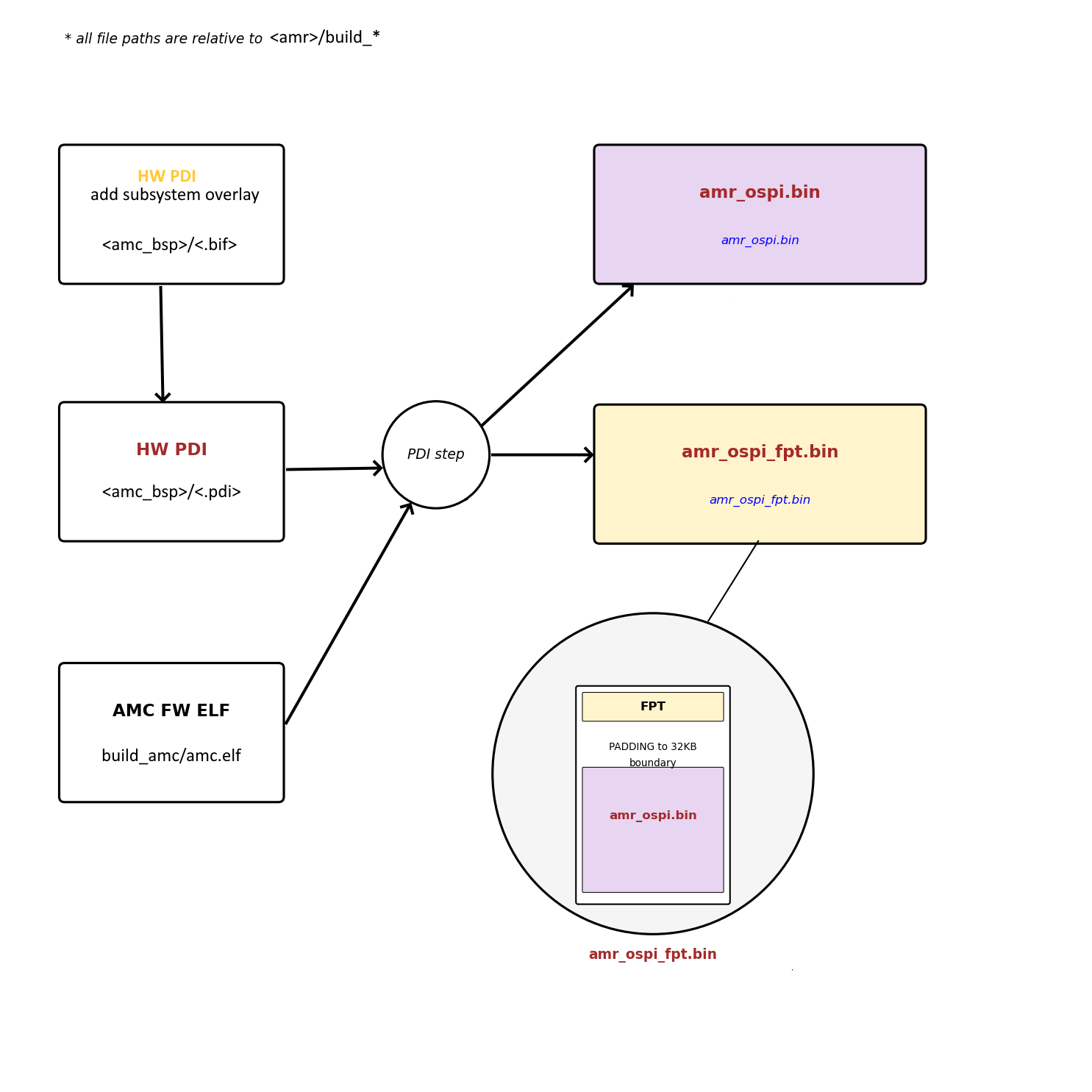
The amr_ospi_fpt.bin is intended to be written to flash over JTAG using HW Manager. This PDI sets up the flash so that it can be used by AMC/AMI.
This basically means that it contains the FPT at the beginning of the OSPI flash memory, which AMI/AMC can then process to determine where in flash it can write different PDIs. Padding is added between the amr_ospi_fpt.bin and the amr_ospi.bin to ensure that the amr_ospi.bin is aligned to a 32KB boundary (this is a requirement of the PMC boot search).
Effectively, the amr_ospi_fpt.bin configures the flash to contain the FPT along with amr_ospi.bin in the 1st PDI Partition.
Writing amr_ospi_fpt.bin to flash is only required if the FPT has been modified. Otherwise, if the FPT in flash is still valid, then the amr_ospi.bin can be written to one of the PDI partitions over PCIe using AMI.