Baremetal Flow Example
To use SOM without Linux, you create a baremetal (also called standalone) application. This example flow details the process of creating a simple programmable logic (PL) design with a block RAM connected to the processing system (PS), running on the Vision AI Starter Kit. The flow then creates a standalone software in AMD Vitis™ to read and write from block RAM. Finally, the flow suggests two ways to load and test the application on SOM.
Assumption: AMD built carrier cards with a corresponding SOM Starter Kit board file
Input: SOM Starter Kit board files (in AMD Vivado™), your own accelerator designs in Vivado (in this case, block RAM)
Output:
<pl>.bit,fsbl.elf,pmufw.elf,<application>.elf, andboot.bin
Prerequisites and Assumptions
This document assumes that you use 2021.1 or later tools and SOM content releases. The tool versions should match, that is, use the same tool versions for Vivado, Vitis, Bootgen, and XSDB.
Vitis tools installation, which include Vivado, Bootgen, and XSDB.
Vivado Board File
This flows starts with Vivado board files containing information on K26, K24, KV260 CC, KR260 CC, or KD240 CC. The K26/K24 SOM is supported in Vivado with board files that automate the configuration of the board peripherals. These board files are available in Vivado’s board list in the Create Project wizard.
For a list of board files required, the tool versions that support them, and how to download them from the XHUB store correctly, refer to the Wiki.
Step 1: Generate the PL Design in Vivado
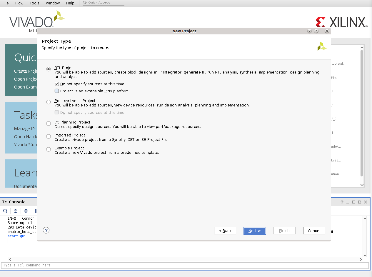
Start Vivado. Choose File -> Project -> New. Then choose the RTL project:
Click Next, then in
Default Partsection, choose boards, choose the K26*/K24* card (in this case K26C), and then click connections: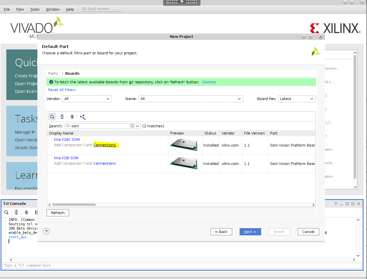
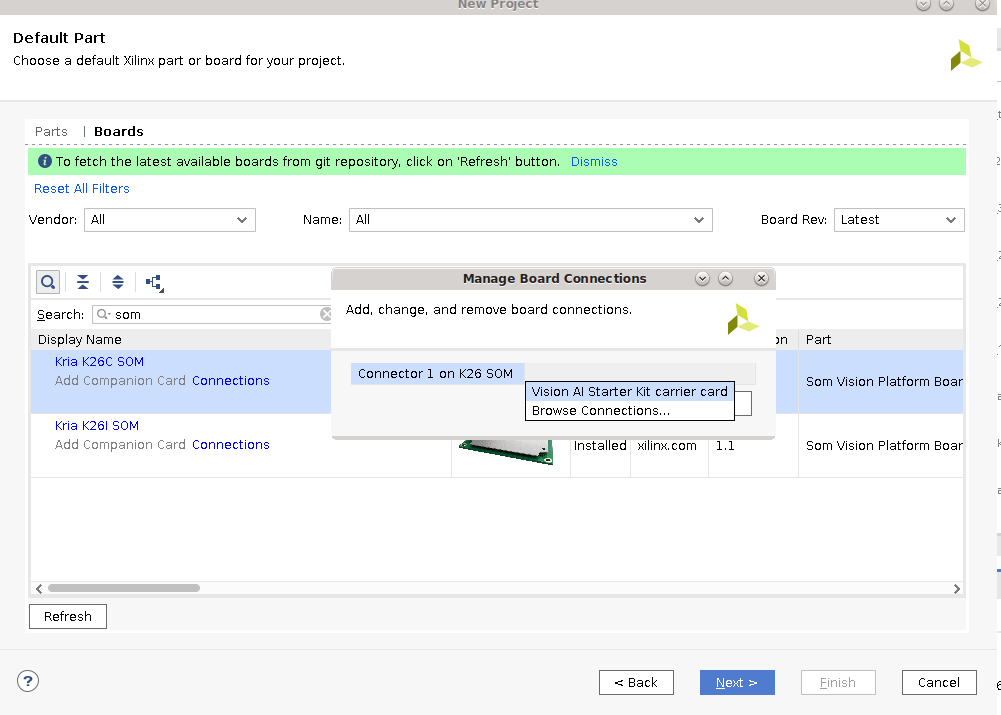
Choose the carrier card to connect the SOM to, which in this case, the Vision AI Starter Kit carrier card:
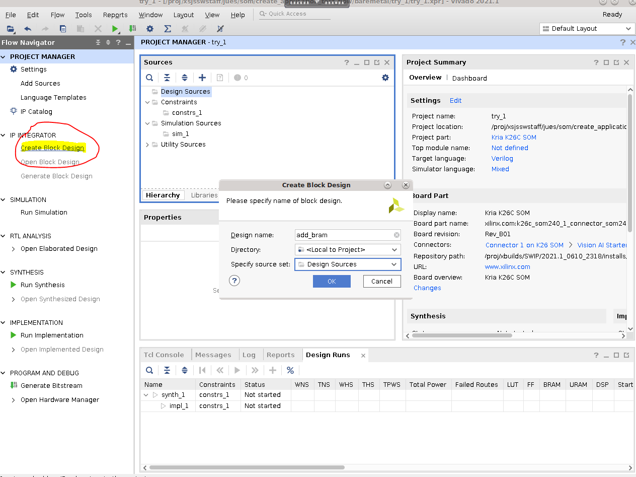
Click through to finish creating the project. Now create a block design:
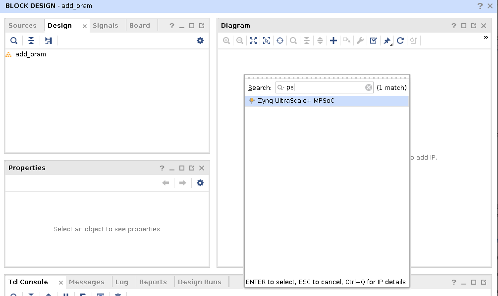
In Block Design, click the + sign, and add the PS block:
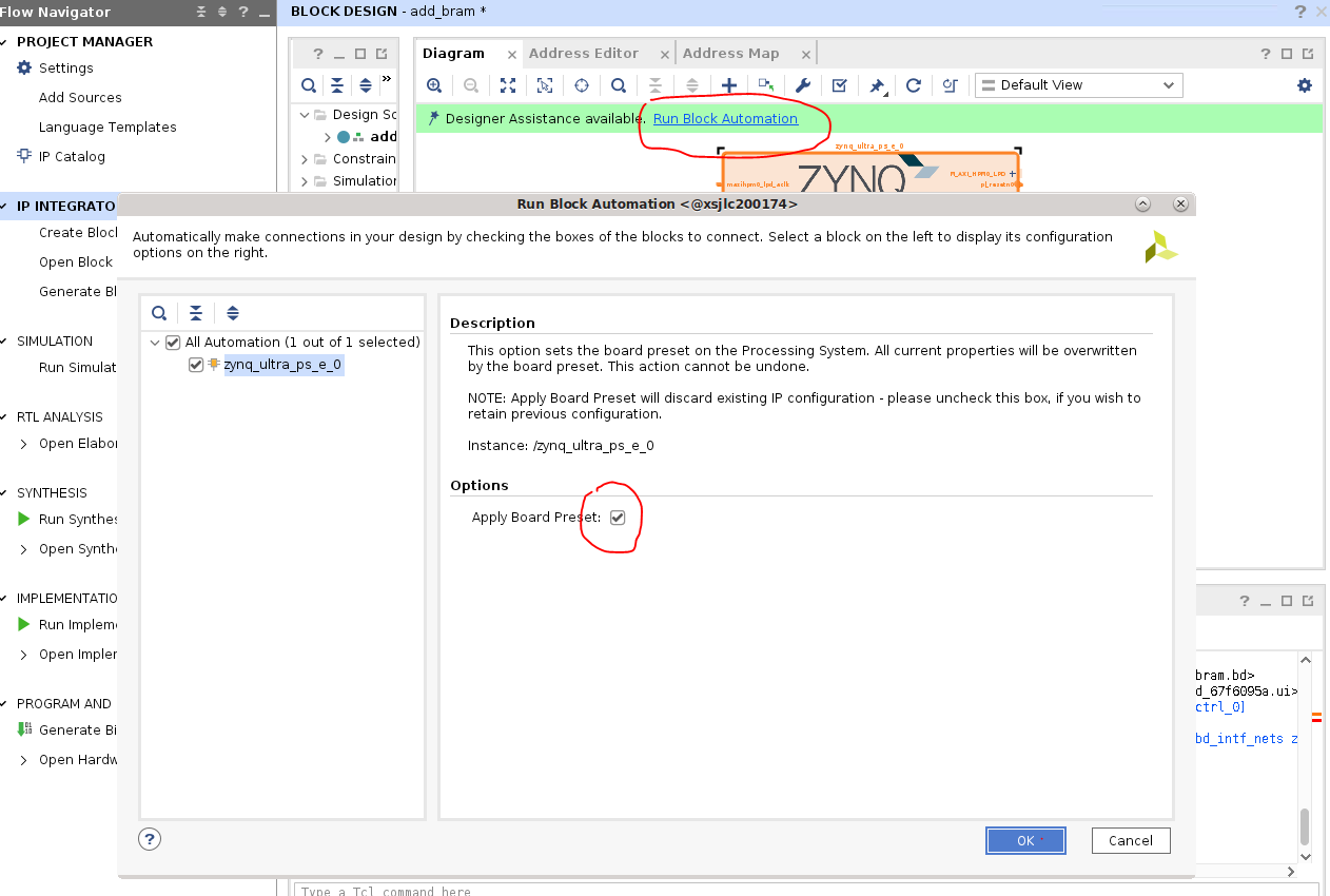
When the PS block is added, make sure to click Run Block Automation, and apply the board preset. This configures the PS block correctly for SOM + Carrier Card:
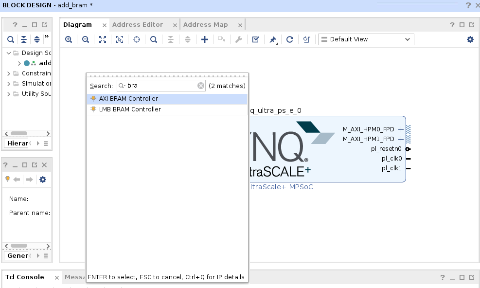
Now add another block: the AXI BRAM controller:
Click Run Connection Automation and connect the
S_AXIport of the block RAM controller with theM_AXI_HPM0port of PS: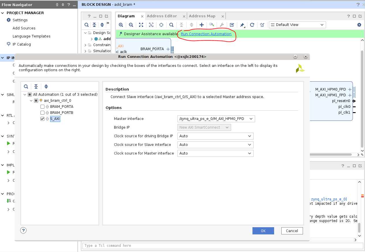
Click Run Connection Automation again, and connect
BRAM_PORTAto a block RAM: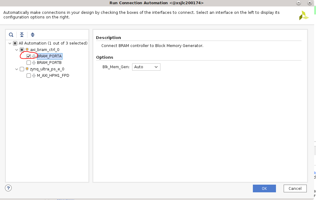
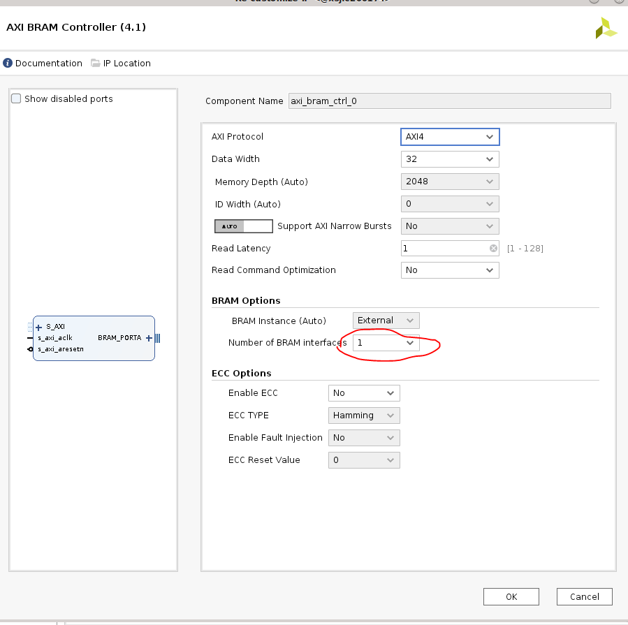
Double-click the block RAM controller, and configure it to only have one block RAM interface:
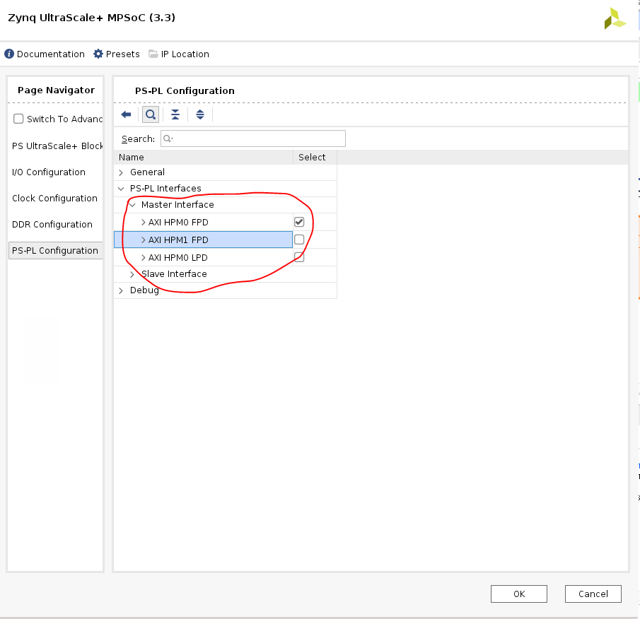
Double-click the PS block, select PS-PL Configuration, and configure it to only enable HPM0 (deselect HPM1):
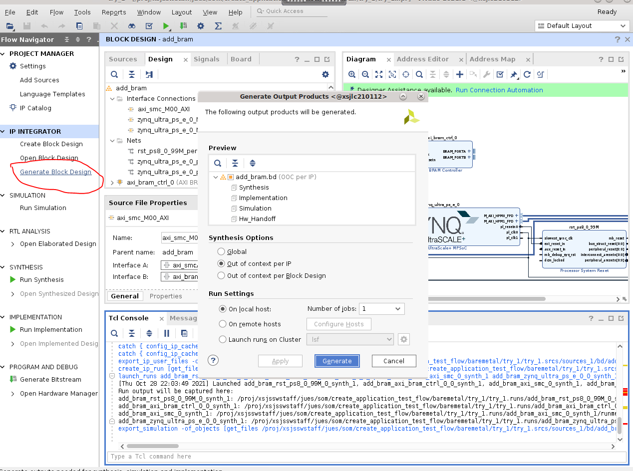
Now connections are complete. Click Generate Block Design:
After it done generating, right click the block design you have created, and select Create HDL Wrapper; this will set the created block design as top module:

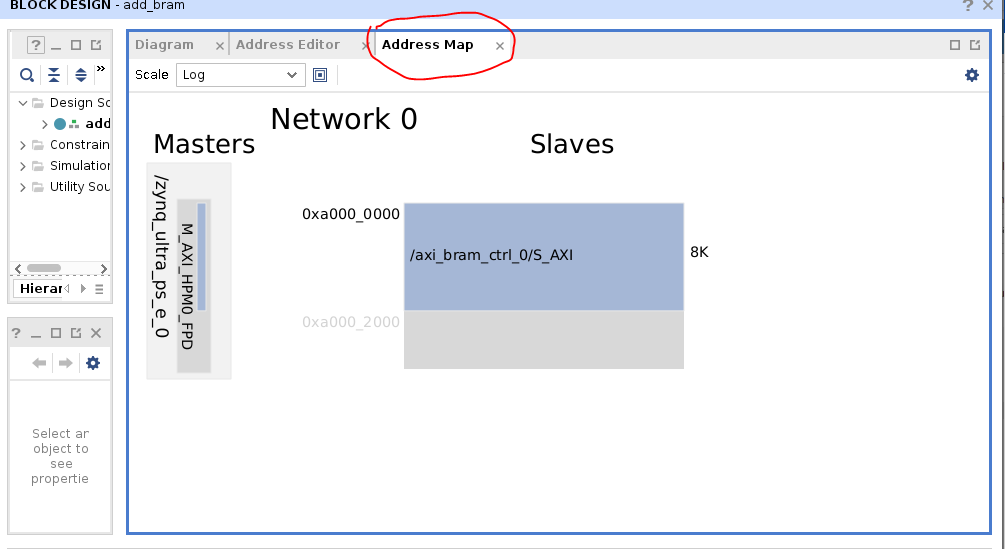
Check the address map of the BRAM slave memory so you can use the same address in the software later:
Generate the bitstream:
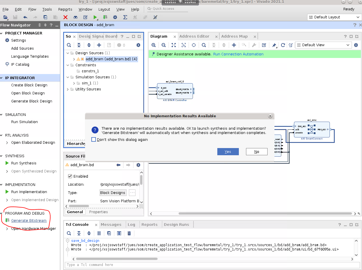
This generates a bitstream at
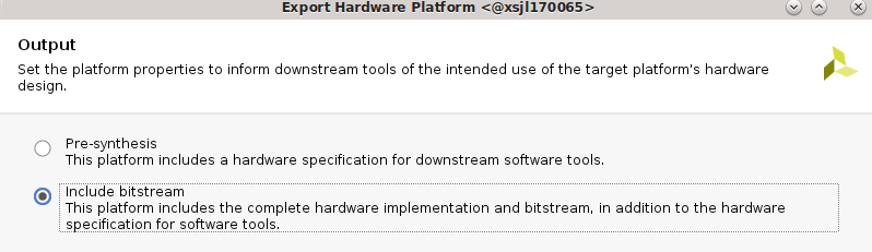
try_1/try_1.runs/impl_1/add_bram_wrapper.bit.Finally, export the .xsa file to work the next step in Vitis:
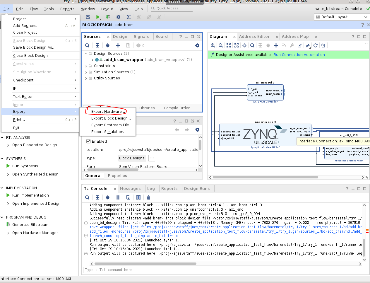
Select Include bitstream:
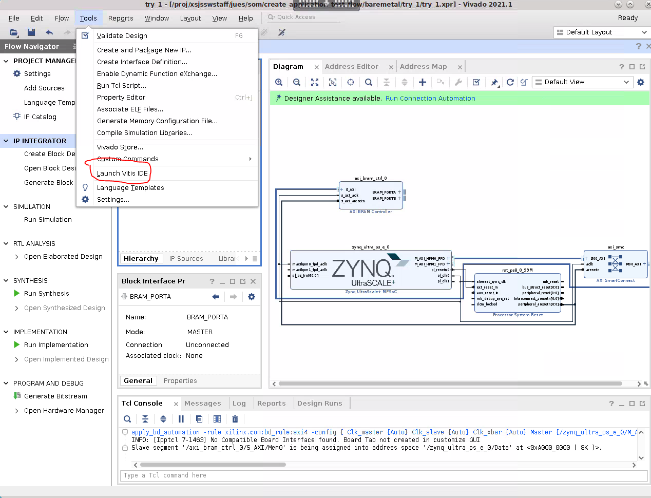
Launch Vitis by selecting Tools -> Launch Vitis IDE:
Step 2: Generate Standalone Software in Vitis
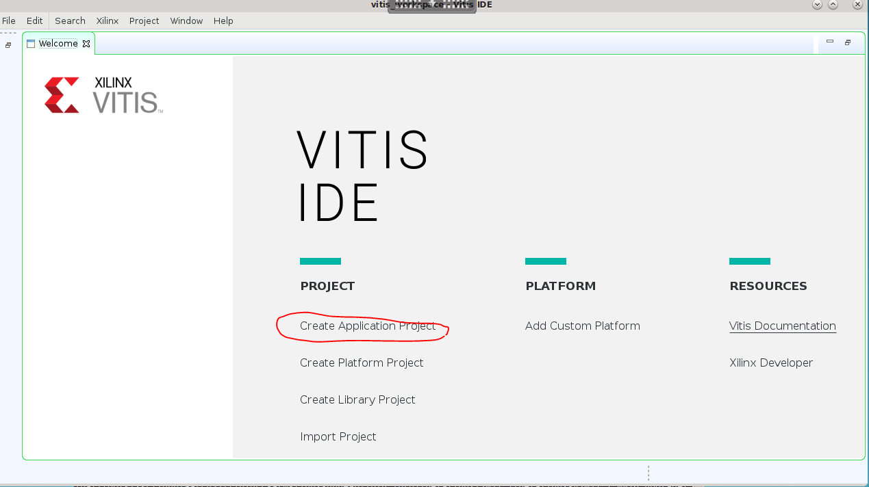
In Vitis, select Project -> Create Application Project:
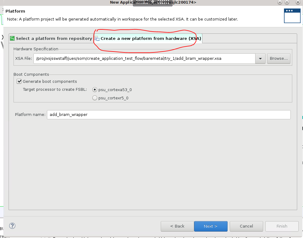
Select Create a new platform from hardware (XSA), and point to the .xsa file that was just exported in step 1:
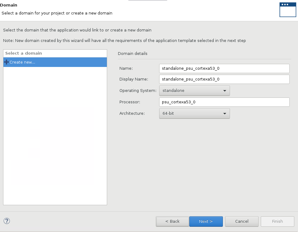
Name the application and associate with PSU_cortexa53_0:
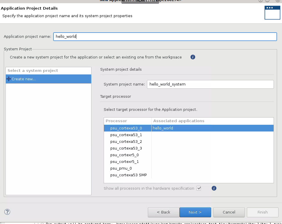
Use
Hello Worldas a template: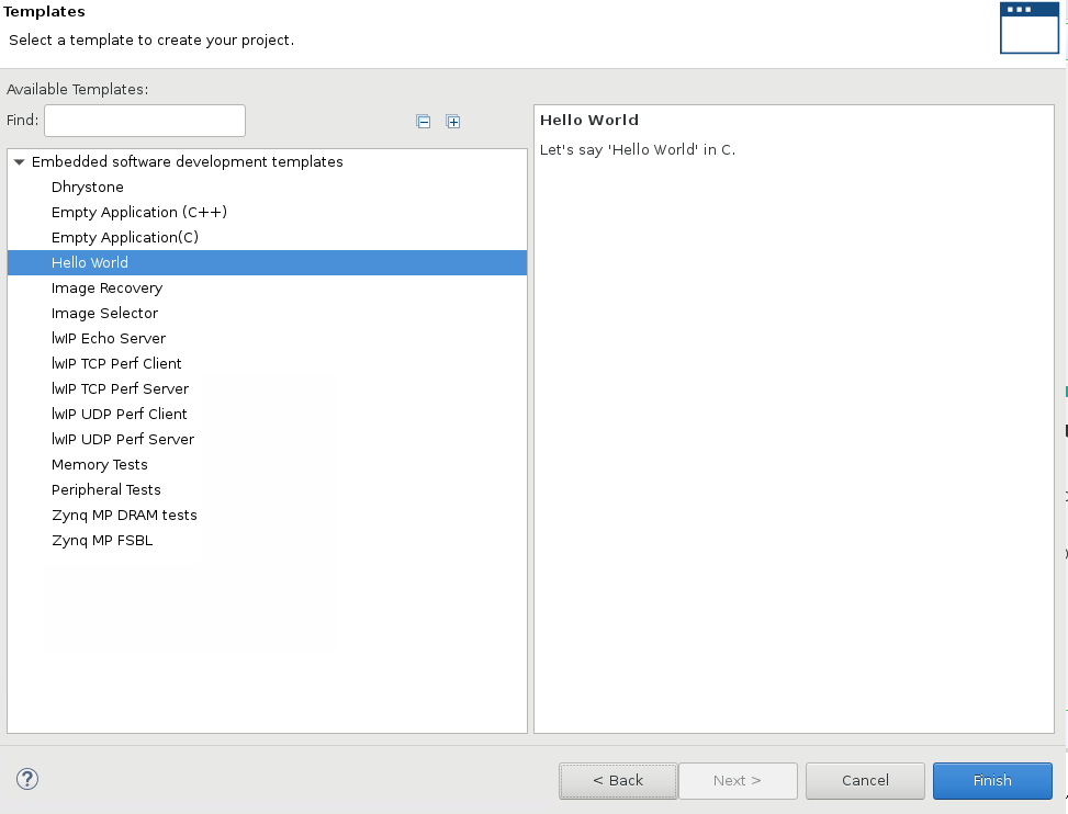
In
helloworld.c, alter the code to read and write from BRAM, and then right-clickhello_world_systemand selectBuild Project: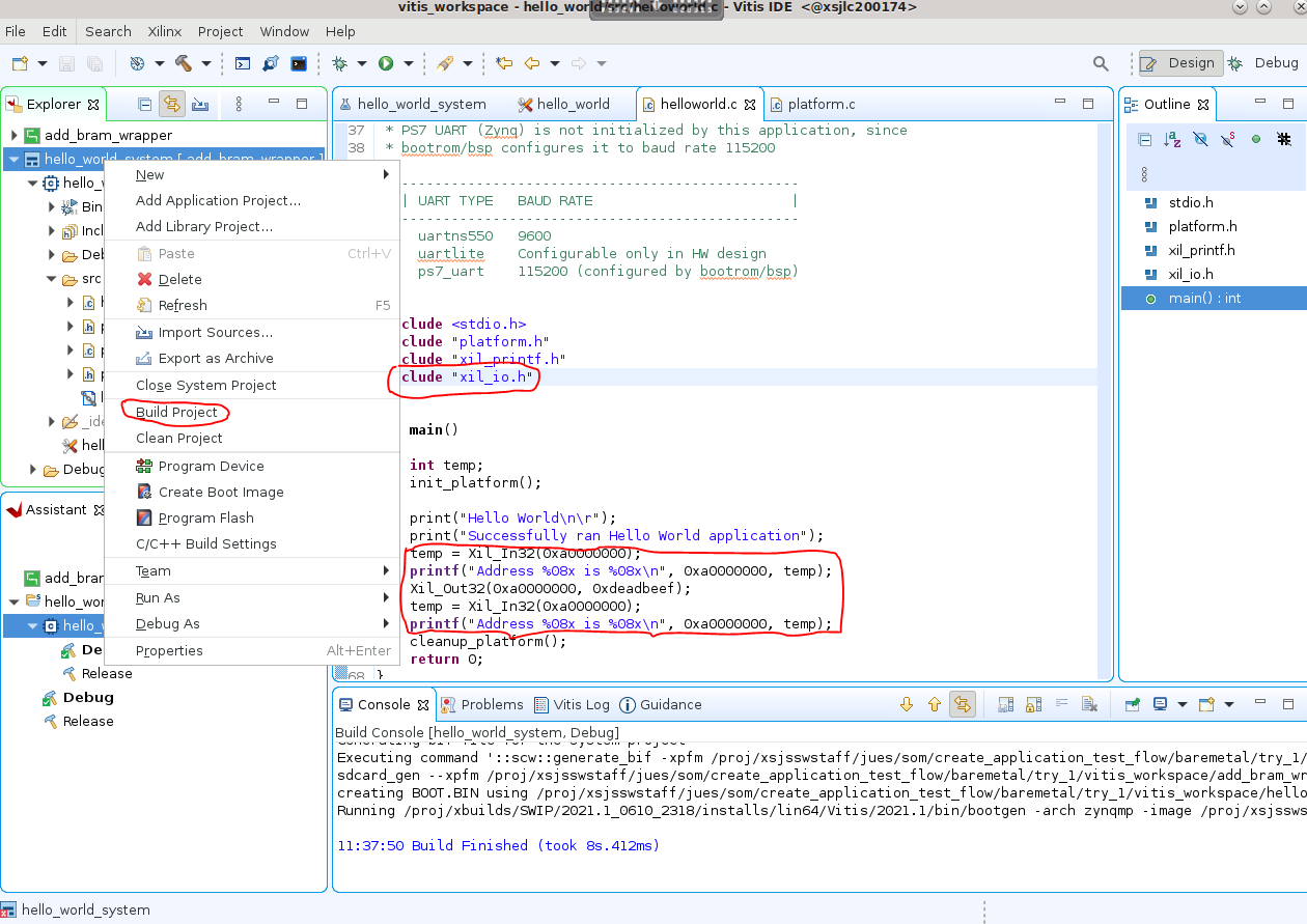
You now have the following files:
vitis_workspace/add_bram_wrapper/export/add_bram_wrapper/sw/add_bram_wrapper/boot/fsbl.elf
vitis_workspace/add_bram_wrapper/export/add_bram_wrapper/sw/add_bram_wrapper/boot/pmufw.elf
vitis_workspace/hello_world/Debug/hello_world.elf
Step 3: Boot Baremetal Applications
There are two ways to boot baremetal applications: using JTAG to download files and start the application, and programming the boot files into the boot image sectors of QSPI so that the application boots up upon power up without needing XSDB. JTAG booting is ideal for development and debugging, while QSPI booting is ideal for deployment.
Option 1: Boot Using JTAG
You can boot using JTAG using the four files generated: fsbl.elf, pmufw.elf, hello_world.elf, and add_bram_wrapper.bit using the following XSDB script:
proc boot_jtag { } {
############################
# Switch to JTAG boot mode #
############################
targets -set -filter {name =~ "PSU"}
# update multiboot to ZERO
mwr 0xffca0010 0x0
# change boot mode to JTAG
mwr 0xff5e0200 0x0100
# reset
rst -system
}

connect
boot_jtag

after 2000
targets -set -filter {name =~ "PSU"}
fpga "add_bram_wrapper.bit"
mwr 0xffca0038 0x1FF

# Download pmufw.elf
targets -set -filter {name =~ "MicroBlaze PMU"}
after 500
dow pmufw.elf
con
after 500

# Select A53 Core 0
targets -set -filter {name =~ "Cortex-A53 #0"}
rst -processor -clear-registers
dow fsbl.elf
con
after 10000
stop


dow hello_world.elf
after 500
con
Option 2: Boot Using boot.bin
Alternatively, you can generate a boot.bin file to be programmed into the A/B image update section.
You first need to create a <test>.bif file containing the following:
the_ROM_image:
{
    [fsbl_config] a5x_x64
    [pmufw_image]pmufw.elf
    [bootloader]fsbl.elf
    [destination_device=pl]add_bram_wrapper.bit
    [destination_cpu=a5x-0]hello_world.elf

}
Then run bootgen to create boot.bin:
bootgen -arch zynqmp -image test.bif -o boot.bin
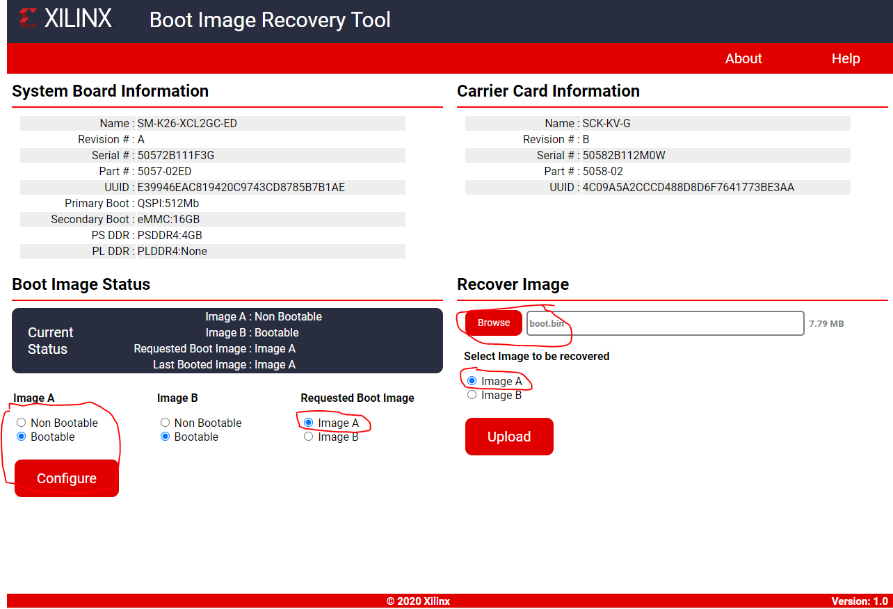
Then, use the firmware update and recovery utility documented in the Wiki
to update the boot firmware. In this example, write boot.bin into Image A. Make sure to mark Image A as bootable, and as the requested Boot Image so that SOM boots Image A on every power cycle.
Step 4: Observe the UART Output
After step 3, .bit file and the .elf files are programmed. Observe printouts from UART indicating the ability to write and read from the block RAM.
Optional: Restoring Linux Booting Image
You might want to restore a Starter Kit back to its default image and Linux boot firmware after one of the image sectors has been overwriten with the baremetal boot file. In that case, download the released Linux booting BOOT.bin from the SOM Wiki and program it into one of the boot image sectors. Then mark that image sector as bootable and requested image.
Copyright © 2023-2025 Advanced Micro Devices, Inc.