3.1. Board and System settings
3.1.1. Prerequisites
- Prebuilt SD Image zip file
- Terminal emulator, for example
- Windows: teraterm (https://osdn.net/projects/ttssh2)
- Linux: picocom (https://github.com/npat-efault/picocom/releases)
- Windows: Win32 Disk Imager utility (https://sourceforge.net/projects/win32diskimager)
- Windows: 7zip utility (https://sourceforge.net/projects/sevenzip/)
3.1.2. Reference Design SD Card Creation
The reference design prebuilt SD image zip files can be downloaded from the below locations. Note there is a separate zip file per platform:
| Platform | 2D filter | XVDPU |
|---|---|---|
| vck190_es1_mipiRxSingle_hdmiTx | vck190_base_trd_single_es_filter2d_prebuilt | |
| vck190_es1_mipiRxQuad_hdmiTx | vck190_base_trd_quad_es_filter2d_prebuilt | vck190_base_trd_quad_es_xvdpu_prebuilt |
| vck190_es1_hdmiRx_hdmiTx | vck190_base_trd_hdmi_es_filter2d_prebuilt | |
| vck190_mipiRxSingle_hdmiTx | vck190_base_trd_single_filter2d_prebuilt | vck190_base_trd_single_xvdpu_prebuilt |
| vck190_mipiRxQuad_hdmiTx | vck190_base_trd_quad_filter2d_prebuilt | vck190_base_trd_quad_xvdpu_prebuilt |
| vck190_hdmiRx_hdmiTx | vck190_base_trd_hdmi_filter2d_prebuilt |
Unzip the downloded file. This should contain the zipped wic image petalinux-sdimage.wic.xz
and a readme file pointing to Third party licenses and sources associated with this image.
Choose an unpartitioned SD card of size 8GB or greater for this demo. Use the
Win32 Disk Imager utility for Windows or ‘dd’ command line utility for Linux
to write the given raw disk image petalinux-sdimage.wic to the SD card.
After unzipping the image file petalinux-sdimage.wic.xz using the 7zip
utility on Windows, use the following steps to write a raw disk image to a
removable device using the Win32 Disk Imager utility.
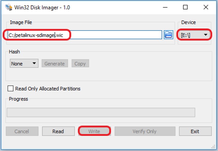
Browse to the location of the unzipped image in the Win32 utility. In the ‘File name’ field, type
*.wic, otherwise only files with the.imgending file be shown. Alternatively, change the drop down menu on the bottom right from ‘Disk Images (*.img *.IMG)’ to ‘*.*’.Choose the correct SD card drive letter under ‘Device’
Select ‘Write’ to the SD card, click ‘Yes’ at the prompt to continue writing and wait till the operation is complete
Steps to write a raw disk image to a removable device using dd command-line utility for Linux
unzip the given image file
petalinux-sdimage.wic.xzin linuxUse dd to write
petalinux-sdimage.wicto correct enumerated disk for SD card in the Linux machine:unxz petalinux-sdimage.wic.xz sudo dd if=petalinux-sdimage.wic of=/dev/sdbx bs=1M
SD card partitions
Once the raw image is written to the SD card, you will be able to see two partitions. The first partition (FAT16 format) is the boot partition and it contains:
- Xilinx OpenCL binary container (
binary_container_1.xclbin) - Boot image (
BOOT.BIN) - u-boot boot script (
boot.scr) - Linux kernel image (
image.ub) - Initial filesystem in ramdisk (
ramdisk.cpio.gz.u-boot)
while in the second patition (ext4 format) resides the root file system.
Note: A Windows OS would only allow FAT16 partitions to be viewed whereas the ext4 format is not recognized.
3.1.3. System Controller
Note
If you think that you have the correct System Controller (SC) SD Image then this section can be skipped.
ES Silicon
The image and instructions to write to the SC SD card can be downloaded from the VCK190 headstart lounge.
- SC SD Image: https://www.xilinx.com/member/vck190_headstart/Board_Framework_Phase1Beta_V1.02_wVadj.img.zip
- Instructions: https://www.xilinx.com/member/vck190_headstart/Update_System_Controller_uSD_Card_Instructions.pdf
Production Silicon
The image (Beta 2.1) and instructions to write to SC SD card are avaialble on the Beam Tool page
3.1.4. Board Setup
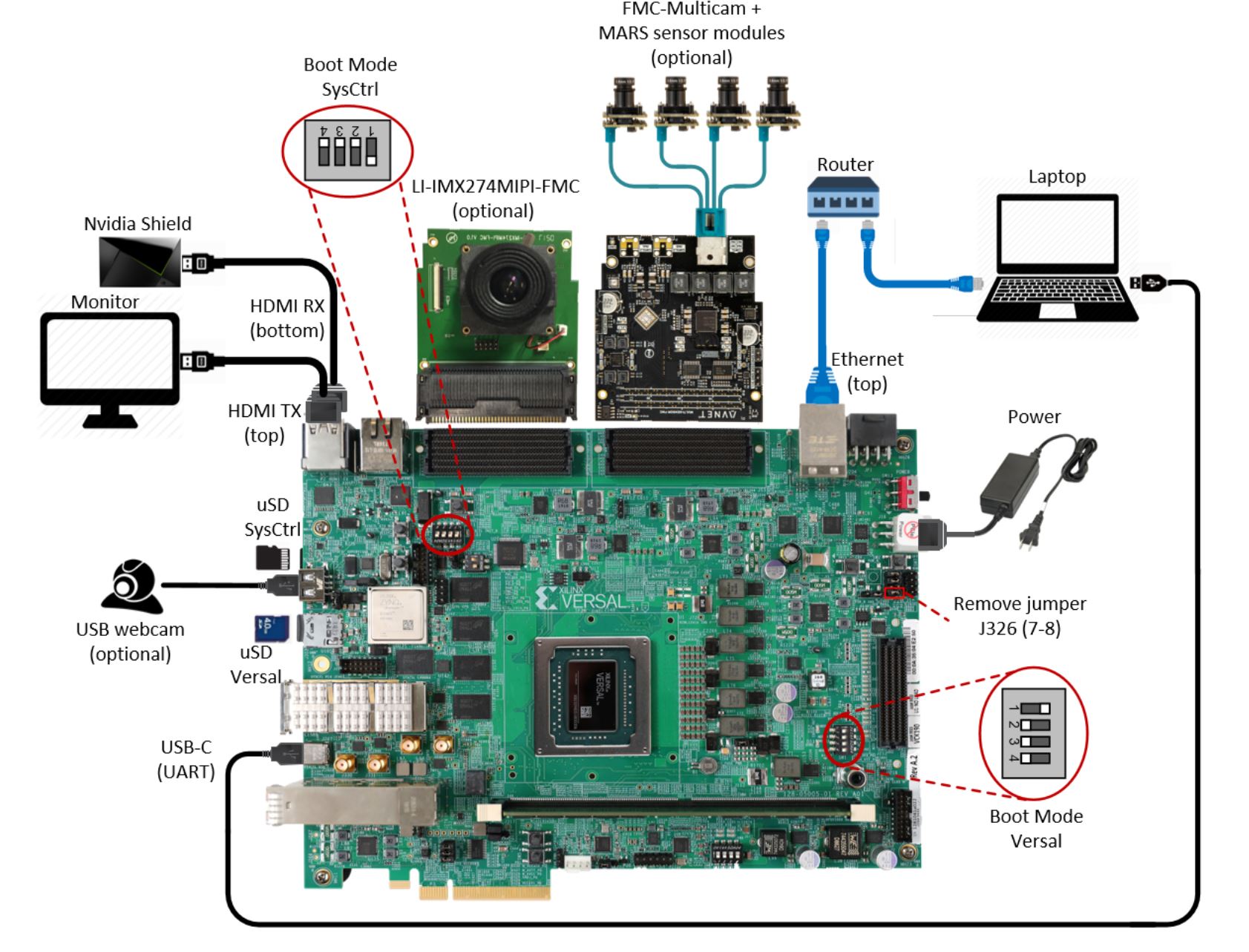
The following figure shows how to set up the VCK190 evaluation board.
Board jumper and switch settings
This is a onetime setup and the board should have been delivered to you with this default settings, but it is good to double check for the first time when you get the board.
- Make sure you remove J326 (7-8) jumper.
- Setup SYSCTRL Boot mode switch SW11 to (ON,OFF,OFF,OFF) from switch bits 1 to 4 as shown in the above picture.
- Make sure you have the SYSCTRL uSD card inserted in the slot and card has the SYSCTRL image.
- Setup Versal Boot Mode switch SW1 to (ON,OFF,OFF,OFF) from switch bits 1 to 4 as shown in the above picture.
MIPI and HDMI connections
Make the connections based on the SD Image selected.
vck190_mipiRxSingle_hdmiTx supports video capture from the Leopard IMX274 MIPI FMC, connect the FMC card to the FMCP1 slot (J51) as shown in the above figure. For more info on the FMC module, visit: https://leopardimaging.com/product/csi-2-mipi-modules-i-pex/li-imx274mipi-fmc/
vck190_mipiRxQuad_hdmiTx supports video capture from Avnet Multi-Camera MIPI FMC Module. Connect the FMC card to the FMCP2 slot (J53) as shown in the above figure. For more info on the FMC module, visit: https://www.avnet.com/wps/portal/silica/products/new-products/npi/2018/avnet-multi-camera-fmc-module/
vck190_hdmiRx_hdmiTx supports video capture via HDMI RX. Connect the HDMI cable as shown in the above figure. Connect the other end of the cable to a HDMI source like a laptop or Nvidia Shield or Roku
Serial console settings
VCK190 comes with a USB-C connector for JTAG+UART, when connected three UART ports should be visible in Device Manager:
- Versal UART0
- Versal UART1 &
- System Controller UART
Connect a USB-C cable to the USB-UART connector. Open two terminal emulator windows. Choose Versal UART0 on one and System Controller UART on the other and use the following settings on the Serial Port:
- Baud Rate: 115200
- Data: 8 bit
- Parity: None
- Stop: 1 bit
- Flow Control: None
Vadj settings
Perform the following steps to set the Vadj voltage rail to 1.2V using the BoardUI/Board Interface Test(BIT) utility:
Note: This is required only if using MIPI Single or Quad sensors.
Power on the board.
Note: Skip next 2 steps for ES silicon
On the System Controller UART terminal type the following commands at the linux prompt. This will allow the BoardUI/Board Interaface Test utility to communicate with the System Controller. For more information refer to http://wiki.xilinx.com/BEAM+Tool+for+VCK190+Evaluation+Kit
EXT<Enter key><Tab Key>
sed -i -e 's/^#//' /etc/init.d/start_boardframework.sh
/etc/init.d/start_boardframework.sh
Close the System Controller UART terminal
Download the BoardUI/Board Interface Test(BIT) tool from the following link:
Extract the zip file and start the BoardUI/Board Interface Test(BIT) tool by clicking on BoardUI.exe. Make sure the USB-C cable is connected to your PC and the system controller Micro SD card is inserted. Also make sure you Vivado Design Suite HW Manager is installed on the host machine.
In the BoardUI GUI, navigate to the FMC Boot Up tab following the red circles as shown in the below figure. Enter 1.2 in the Set On-Boot VADJ field and click the button next to it to save the value.
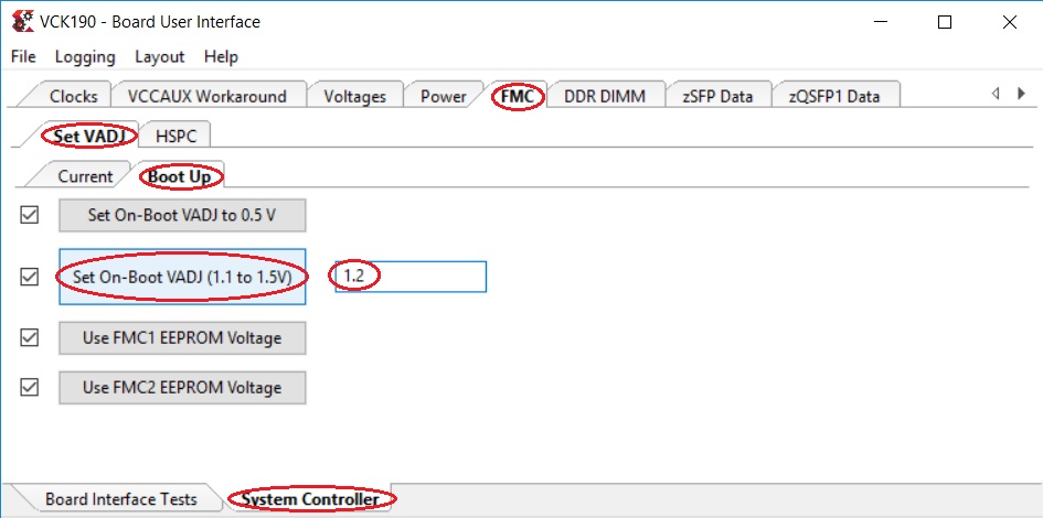
Power-cycle the board and navigate to the FMC Current tab. Click the Get VADJ_FMC Voltage button to read out the current voltage setting and confirm it matches the 1.2V set in the previous step.
Close the BoardUI utility.
Note
If Vadj does not persists after reboot, try updating the System Controller SD card image (Instructions provided in the System Controller section of this tutorial).
Licensed under the Apache License, Version 2.0 (the “License”); you may not use this file except in compliance with the License.
You may obtain a copy of the License at [http://www.apache.org/licenses/LICENSE-2.0](http://www.apache.org/licenses/LICENSE-2.0)
Unless required by applicable law or agreed to in writing, software distributed under the License is distributed on an “AS IS” BASIS, WITHOUT WARRANTIES OR CONDITIONS OF ANY KIND, either express or implied. See the License for the specific language governing permissions and limitations under the License.