3. Run the Prebuilt Image
3.1. Prerequisites
Reference design zip file
Terminal emulator, for example
Windows: teraterm (https://osdn.net/projects/ttssh2)
Linux: picocom (https://github.com/npat-efault/picocom/releases)
Windows: Win32 Disk Imager utility (https://sourceforge.net/projects/win32diskimager)
- Host Machine
Install Qt 5.9
Install OpenCV 3.4.11
3.2. SD Card Creation
Choose an unpartitioned SD card of size 8GB or greater for this demo. Use the
Win32 Disk Imager utility for Windows or ‘dd’ command line utility for Linux
to write the given rawdisk image sdcard.img to the SD card.
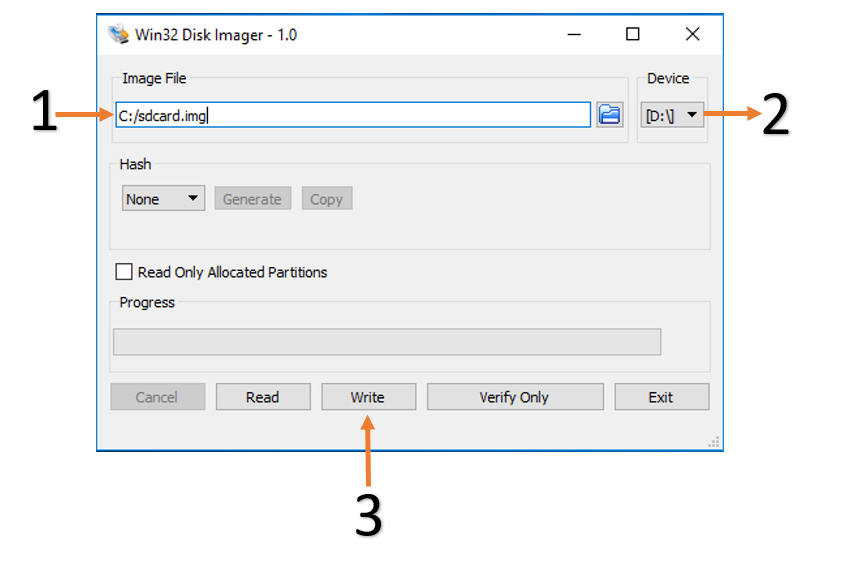
After unzipping the image file sdcard.zip using windows extractor, use
the following steps to write a raw disk image to a removable device using the
Win32 Disk Imager utility.
Browse to the location of the unzipped image in the Win32 utility
Choose the correct SD card under ‘device’
Select ‘Write’ to the SD card, click ‘Yes’ at the prompt to continue writing and wait till the operation is complete
Steps to write a raw disk image to a removable device using dd command-line utility for Linux
Unzip the given image file
sdcard.zipin linuxUse dd to write
sdcard.imgto correct enumerated disk for SD card in the Linux machine:unzip sdcard.zip sudo dd if=sdcard.img of=/dev/sdbx bs=1M
SD card partitions
Once the raw image is written to the SD card, you will be able to see two partitions. In the first partition (FAT32 format) resides:
Boot image (
BOOT.BIN)u-boot boot script (
boot.scr)Linux kernel image (
Image)XCLBIN (
binary_container_1.xclbin)
while in the second patition (ext4 format) resides the root file system.
Note: A Windows OS would only allows FAT32 partitions to be viewed, which is the boot partition, whereas ext4 format is not recognized.
3.3. Board Setup
The following figure shows how to set up the VMK180 evaluation board.
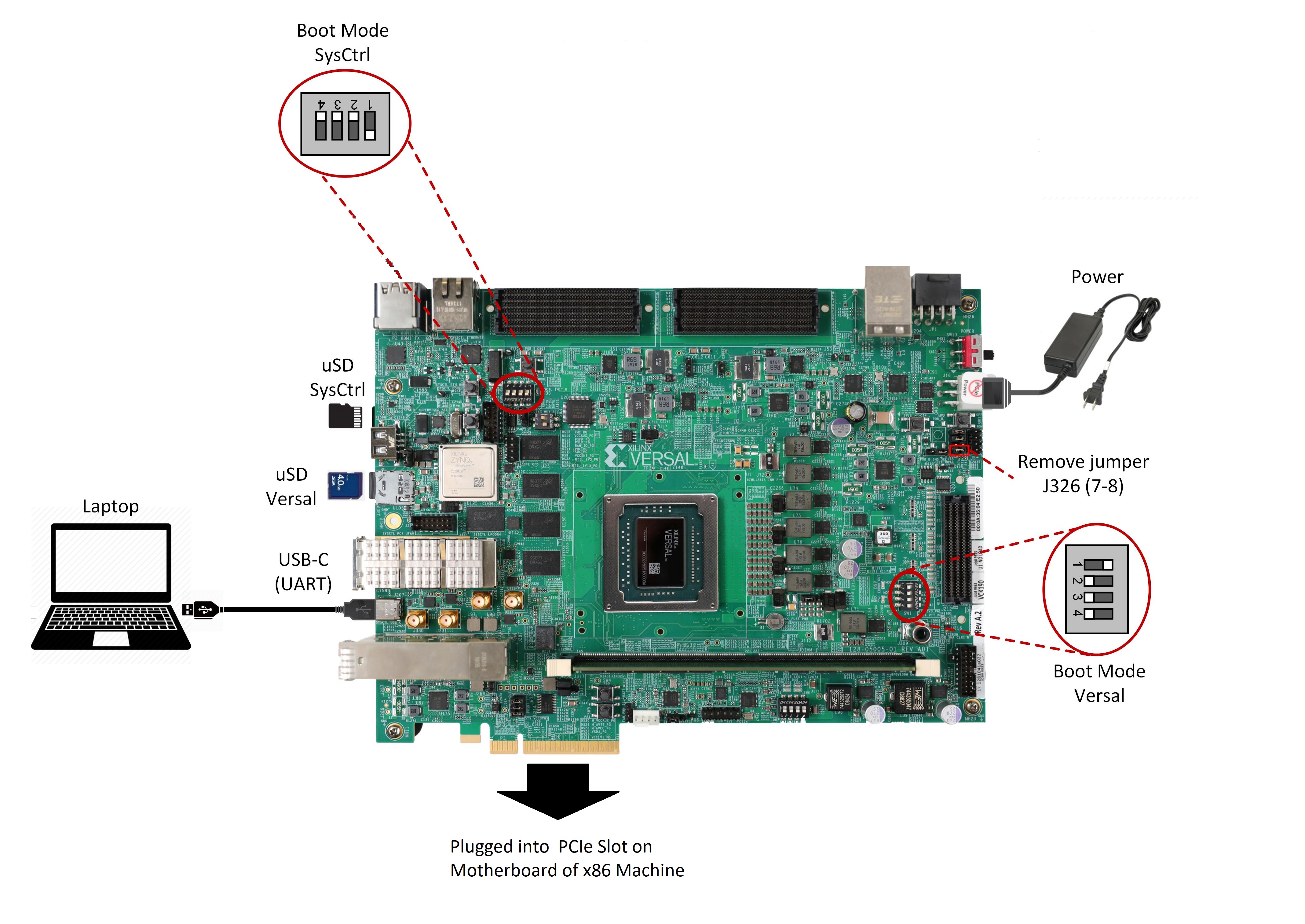
Board jumper and switch settings
This is a onetime setup and the board should have been delivered to you with this default settings, but it is good to double check for the first time when you get the board.
Make sure you remove J326 (7-8) jumper.
Setup SYSCTRL Boot mode switch SW11 to (ON,OFF,OFF,OFF) from switch bits 1 to 4 as shown in the above picture.
Make sure you have the SYSCTRL uSD card inserted in the slot and card has the SYSCTRL image.
Setup Versal Boot Mode switch SW1 to (ON,OFF,OFF,OFF) from switch bits 1 to 4 as shown in the above picture.
Serial console settings
VMK180 comes with a USB-C connector for JTAG+UART, when connected three UART ports should be visible in Device Manager:
Versal UART0
Versal UART1 &
System Controller UART
Connect a USB-C cable to the USB-UART connector. In the terminal emulator choose Versal UART0 and use the following settings:
Baud Rate: 115200
Data: 8 bit
Parity: None
Stop: 1 bit
Flow Control: None
3.4. Connect to the JupyterLab Server
Follow these steps to boot the board into Linux
Ensure all steps under the section ‘Board jumper and switch settings’ are verified.
Insert the prepared micro SD card into the Versal SD card slot (refer to the image VMK180 Board Setup)
Make physical connections to ethernet, HDMI, UART, webcam and power as shown in the image.
Have the UART0 terminal emulator tab connected.
Turn ON power switch SW13.
On Versal UART0 terminal, we would see the Versal device booting from the micro SD card starting with the message “Xilinx Versal Platform Loader and Manager”
In about 60 seconds boot is complete. Observe the Linux prompt root@xilinx-vmk180-es1-2020_2 and autostart of JupyterLab server as shown in the example below:
root@xilinx-vmk180-es1-2020_2:~#
[W 02:30:21.552 LabApp] JupyterLab server extension not enabled, manually loading...
[I 02:30:21.571 LabApp] JupyterLab extension loaded from /usr/lib/python3.5/site-packages/jupyterlab
[I 02:30:21.572 LabApp] JupyterLab application directory is /usr/share/jupyter/lab
[I 02:30:21.580 LabApp] Serving notebooks from local directory: /usr/share/notebooks
[I 02:30:21.581 LabApp] The Jupyter Notebook is running at:
[I 02:30:21.581 LabApp] http://172.19.1.246:8888/?token=c46d443a39d2648046afdbb9bc5821177ab7cd386c218103
[I 02:30:21.581 LabApp] Use Control-C to stop this server and shut down all kernels (twice to skip confirmation).
[C 02:30:23.092 LabApp]

 To access the notebook, open this file in a browser:
     file:///home/root/.local/share/jupyter/runtime/nbserver-1889-open.html
 Or copy and paste one of these URLs:
     http://172.19.1.246:8888/?token=c46d443a39d2648046afdbb9bc5821177ab7cd386c218103
Follow these steps to connect to the jupyter-server using Chrome browser on the laptop.
Note: This demo is tested with Chrome browser only.
Copy the generated URL with token on the prompt of Versal target and paste it to the browser address bar of the laptop, for example:
http://172.19.1.246:8888/?token=c46d443a39d2648046afdbb9bc5821177ab7cd386c218103Note: If for any reason target fails to grab an IP address from the network, Jupyter server would fail to issue an URL. In such a case user is recommended to fix an IP address and restart the jupyter server as shown below:
/etc/init.d/jupyterlab-server stop
/etc/init.d/jupyterlab-server start
To look up the jupyter server IP address and token on the target, run:
jupyter notebook list
In case of a private network, user may have to assign a static address within the subnet of the host laptop
3.5. Run the Jupyter Notebooks
This TRD includes the following jupyter notebooks:
vmk180-trd-cpu.ipynb: Demonstrates how to plot the CPU usage while running applications and pipelines.
vmk180-trd-power.ipynb: Demonstrates how to plot power consumption of multiple voltage rails throughout the board.
To run the notebooks, follow the below steps:
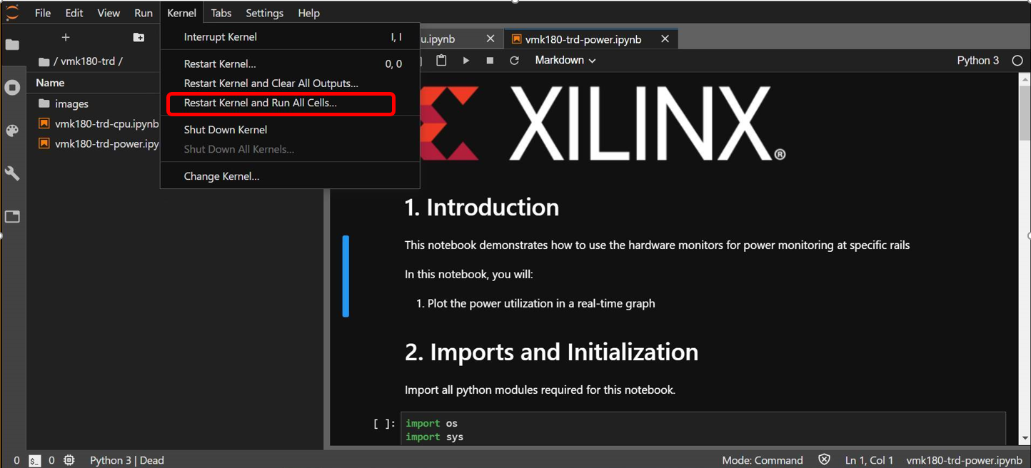
On the left pane of the browser, 2 notebooks are available under the folder vmk180-trd.
Double click to open the notebook
Select ‘Kernel’ → ‘Restart Kernel and Run All Cells’ from the top menu bar to run the demo. Scroll down to the end of the notebook to see the video output.
Click the rectangular icon to interrupt the kernel and stop the video stream.
Select ‘Kernel’ → ‘Shutdown Kernel’ → close the notebook tab and move to the next notebook.
3.6. Host machine Setup
*Directory and file description:
Following are the list of directories in the package.
apps -> QDMA User space application to configure and control QDMA
docs -> Documentation for the Xilinx QDMA Linux Driver
driver/src -> Provides interfaces to manage the PCIe device and exposes character driver interface to perform QDMA transfers
driver/libqdma -> QDMA library to configure and control the QDMA IP
scripts -> Sample scripts for perform DMA operations
Makefile -> Makefile to compile the driver
pcie_app -> This application receives frame buffer data from host, processes it and sends frame buffer to host using QDMA driver
NOTE: Make sure, the VMK180 board is powered on before booting the HOST machine to enumerate VMK180 board as PCIe endpoint device successfully
Insert the VMK180 board into the PCIe slot of the HOST machine and power on the board
Now power on the HOST machine
Execute “lspci” command on HOST machine’s terminal Make sure to see “03:00.0 RAM memory: Xilinx Corporation Device b03f” entry is listed; otherwise QDMA driver will not be able to recognized PCIe endpoint device.
Copy the hosting package and follow steps to Install the QDMA driver NOTE: Root permissions will be required to install qdma driver.
NOTE_1: The follwoing details are w.r.t this TRD. For additional information refer https://xilinx.github.io/dma_ip_drivers/master/QDMA/linux-kernel/html/build.html
- Follow below steps to compile QDMA driver
cd $TRD_HOME/pcie_host_package
cd qdma
make
- Install the QDMA driver
make install-mods
- Configure the QDMA module paramters using following script:
./scripts/qdma_generate_conf_file.sh <bus_num> <num_pfs> <mode> <config_bar> <master_pf>
Ex: (Assuming PCIe BDF - 03:00.0)
./scripts/qdma_generate_conf_file.sh 0x03 1 0 1 0
- For loading the driver, execute the following command: (This is required only First time, from next boot driver loads automatically)
modprobe qdma-pf
- Setup and Enable Queues for H2C and C2H: (Refer link in NOTE_1 for more details)
Allocate the Queues to a function. QDMA IP supports maximum of 2048 queues. By default, all functions have 0 queues assigned. qmax configuration parameter enables the user to update the number of queues for a PF. This configuration parameter indicates “Maximum number of queues associated for the current pf”.
To set 1024 as qmax for PF0:
echo 1024 > /sys/bus/pci/drivers/qdma-pf/$BDF/qdma/qmax
- To Add a Queue:
dma-ctl qdma<bbddf> q add idx <N> [mode <st|mm>] [dir <h2c|c2h|bi>]
EX: (Assuming PCIe BDF - 03:00.0)
dma-ctl qdma03000 q add idx 0 mode mm dir h2c
dma-ctl qdma03000 q add idx 1 mode mm dir c2h
- To start a Queue:
dma-ctl qdma<bbddf> q start idx <N> [dir <h2c|c2h|bi>]
Ex: (Assuming PCIe BDF - 03:00.0)
dma-ctl qdma03000 q start idx 0 dir h2c
dma-ctl qdma03000 q start idx 1 dir c2h
- Build use case application:
cd pcie_app/
NOTE: Please modify macros H2C_DEVICE, C2H_DEVICE, REG_DEVICE_NAME in pcie_host.cpp, usign /dev/ nodes generated for the pcie device based on its Bus:Device:Function number.
Ex: Assuming PCIe BDF as 03:00.0 the above macros need to be set as:
If H2C queue index is 0 device node is “/dev/qdma03000-MM-0” (Queue index for H2C is set in above “Add a queue” step)
If C2H queue index is 1 device node is “/dev/qdma03000-MM-1” (Queue index for C2H is set in above “Add a queue” step)
REG_DEVICE_NAME is “/sys/bus/pci/devices/0000:03:00.0/resource0”
Please modify pcie_app/app1.pro line no 35 and 39 for opencv library path and opencv include path before compilation export QMAKE_PATH to installed QT qmake path
Ex: export QMAKE_PATH=/opt/Qt5.9/5.9/gcc_64/bin/qmake
compile application:
./do_compile.sh
3.7. Run Host and EP applications
Make sure, HOST application is launched before starting EP application.
Execute following command to run the Host application(pcie_host_app)
./pcie_host_app -i < input_file_name > -d < input_resolution > -t < filter_type >
For 1080p, 30fps: ./pcie_host_app -i file.yuy2 -d 1920x1080 -t 4
For 4K, 30fps: ./pcie_host_app -i file.yuy2 -d 3840x2160 -t 4
Execute following command on Target(EP) to start application(pcie-testapp)
- Note: once Linux boots on the Target, it asks for username and password, please type “root” for both
set the following environment variable: export XILINX_XRT=/usr
export XCL_BINDIR=/media/sd-mmcblk0p1/
pcie-testapp
Note
it is safe to ignore any AIE_METADATA related prints on terminal during XCLBIN load. It has no impact on fuctionality.