3. Run the Prebuilt Image
3.1. Prerequisites
Reference design zip file
Terminal emulator, for example
Windows: teraterm (https://osdn.net/projects/ttssh2)
Linux: picocom (https://github.com/npat-efault/picocom/releases)
Windows: Win32 Disk Imager utility (https://sourceforge.net/projects/win32diskimager)
- Host Machine with 4 x 10G NIC
Install iperf3
3.2. SD Card Creation
Choose an unpartitioned SD card of size 8GB or greater for this demo. Use the
Win32 Disk Imager utility for Windows or ‘dd’ command line utility for Linux
to write the given rawdisk image sdcard.img to the SD card.
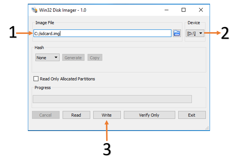
After unzipping the image file sdcard.zip using windows extractor, use
the following steps to write a raw disk image to a removable device using the
Win32 Disk Imager utility.
Browse to the location of the unzipped image in the Win32 utility
Choose the correct SD card under ‘device’
Select ‘Write’ to the SD card, click ‘Yes’ at the prompt to continue writing and wait till the operation is complete
Steps to write a raw disk image to a removable device using dd command-line utility for Linux
Unzip the given image file
sdcard.zipin linuxUse dd to write
sdcard.imgto correct enumerated disk for SD card in the Linux machine:unzip sdcard.zip sudo dd if=sdcard.img of=/dev/sdbx bs=1M
SD card partitions
Once the raw image is written to the SD card, you will be able to see two partitions. In the first partition (FAT32 format) resides:
Boot image (
BOOT.BIN)u-boot boot script (
boot.scr)Linux kernel image (
Image)
while in the second patition (ext4 format) resides the root file system.
Note: A Windows OS would only allows FAT32 partitions to be viewed, which is the boot partition, whereas ext4 format is not recognized.
3.3. Board Setup
The following figure shows how to set up the VMK180 evaluation board.

Board jumper and switch settings
This is a onetime setup and the board should have been delivered to you with this default settings, but it is good to double check for the first time when you get the board.
Make sure you remove J326 (7-8) jumper.
Setup SYSCTRL Boot mode switch SW11 to (ON,OFF,OFF,OFF) from switch bits 1 to 4 as shown in the above picture.
Make sure you have the SYSCTRL uSD card inserted in the slot and card has the SYSCTRL image.
Setup Versal Boot Mode switch SW1 to (ON,OFF,OFF,OFF) from switch bits 1 to 4 as shown in the above picture.
Serial console settings
VMK180 comes with a USB-C connector for JTAG+UART, when connected three UART ports should be visible in Device Manager:
Versal UART0
Versal UART1 &
System Controller UART
Connect a USB-C cable to the USB-UART connector. In the terminal emulator choose Versal UART0 and use the following settings:
Baud Rate: 115200
Data: 8 bit
Parity: None
Stop: 1 bit
Flow Control: None
3.4. External NIC to VMK180 connection
Connect a QSFP cable from external NIC on a host machine to VMK180 QSFP port.
3.5. Versal VMK180 Setup
- SD Boot mode steps:
Place the boot image in sd card and power on the board in SD boot mode.
Hit any command to stop autoboot at u-boot
Set the GT reference clock as mentioned under “Setting the GT reference clock using Board UI” section.
Once clock programming is done enter “boot” command at u-boot.
Once Linux boots, it asks for username and password, please type “root” for both.
Note
The follwoing board settings needs to be done before booting linux images on VMK180, for every fresh boot in all boot modes.
Setting the GT reference clock using Board UI:
Copy the clock files from the clock_files folder of the vmk180_trd_platform3_2020.2 package to BoardUI->tests->VMK180->clockFiles folder.
Open the VMK180 Board UI application. Choose the board information as shown in the figure
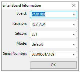
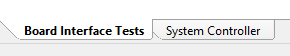
Once the GUI is open, go to File -> Change the System Controller Port. Choose the port corresponding to the system controller. On the bottom left, click on System Controller Tab
Choose the reference clock files to be programmed as shown in the following figure:
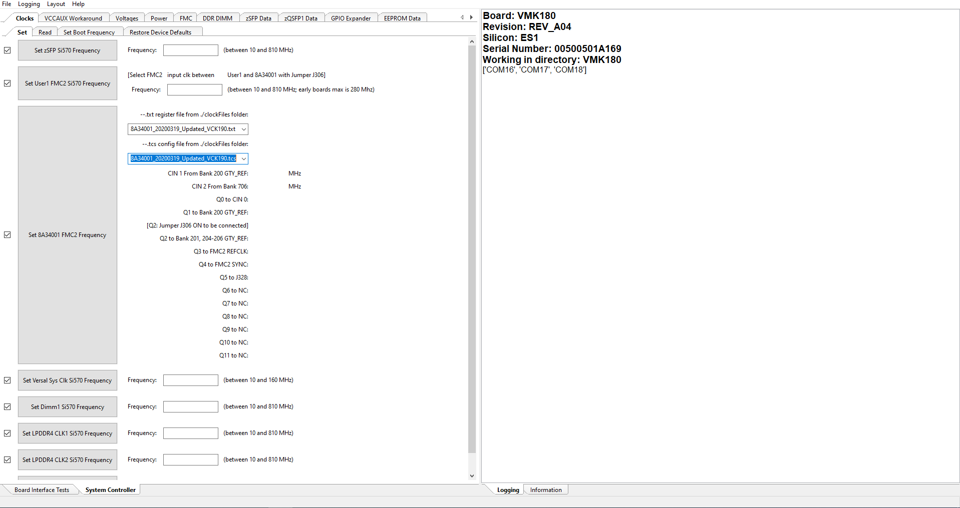
Click on Set 8A34001 FMC2 Frequency. Once the clocks are set, user will see the following in the logs window
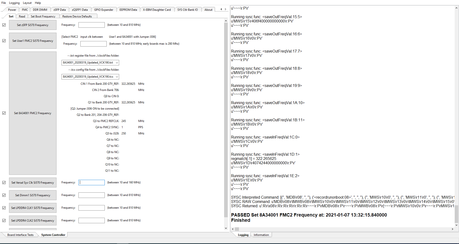
This will program the clocks needed for the design.
3.6. Run Host and VMK180 applications
Once host and vmk180 are booted, setup IP for each ethernet port and make sure ethernet link is established using ping. Once ping is successfull only proceed further.
Execute following command to run the Host utility
iperf3 -s -i 60
Execute following command on Target(EP) to start traffic
iperf3 -c <remote Host IP> -t 60 -i 60