Vector Add lab
Introduction
This lab guides you through the steps involved in creating your first Vitis project targeting both the AI Engine and the Adaptable Engine. You will be implementing a very simple adder kernel in the AI Engine and a few datamovers on the Adaptable Engine. You will simulate and emulate the project. Finally, you will run the lab on real hardware.
References
For more details on the Vitis IDE check out Creating a Vitis IDE Project.
Description of the lab
This lab uses an adder kernel on the AI Engine and three datamovers on the Adaptable Engine (PL), the lab also uses a host code to control the lab.
Concepts
-
The source code is written on C++
-
Linking file
-
Run AI Engine x86 simulation
-
Run AI Engine simulation
Objectives of this lab
After completing this lab, you will learn to:
-
Create a project using the Vitis GUI
-
Run AI Engine software simulation
-
Run AI Engine software emulation
-
Linking kernels between Adaptable and AI Engines
-
Run hardware
Steps
Your journey with Versal devices begins here, buckle up!
Clone repo
Follow these steps to get the source code for this tutorial, Get Source Code
Create a Vitis Project for the VCK5000 Versal Development Card
-
Verify that the tools and VCK5000 platform are setup correctly here
-
In a terminal, start the Vitis IDE by running
vitis -workspace ~/xup_aie_workspaceNote, Vitis will use
~/xup_aie_workspaceas work directory -
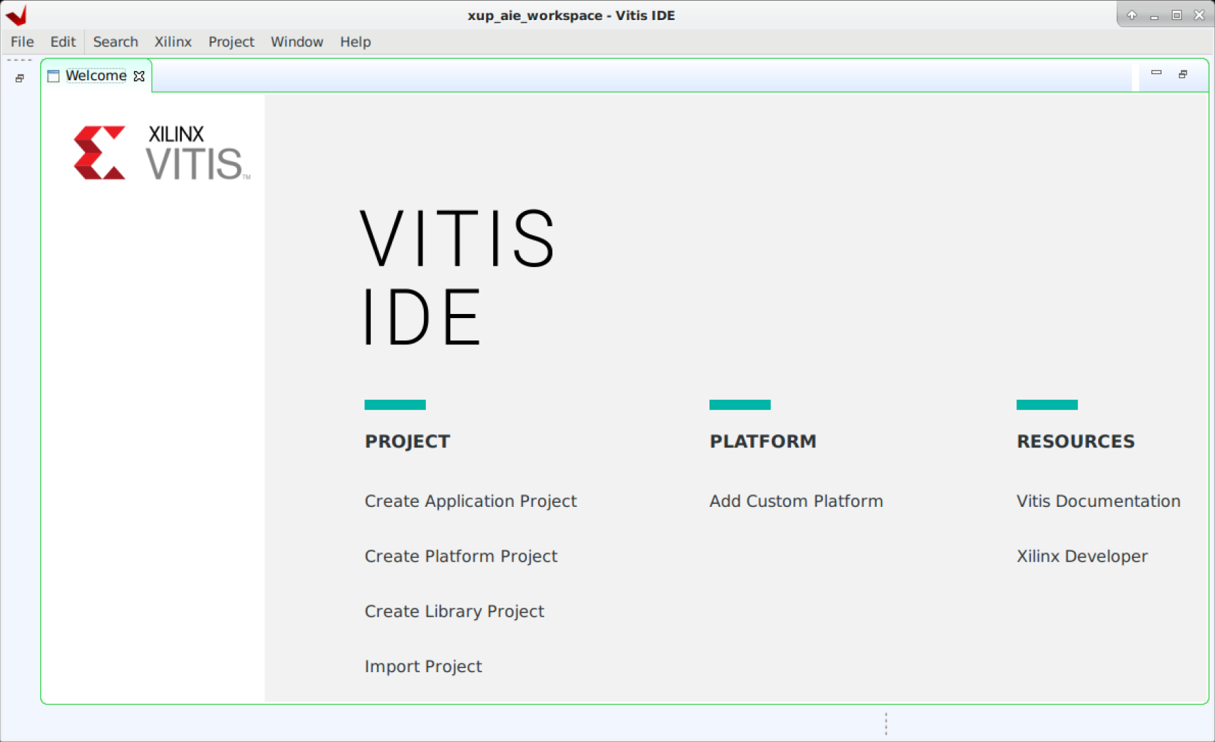
The Vitis IDE Welcome page is displayed
-
Create a new application project
Click Create Application Project from Welcome page, or File > New > Application Project to create a new application
-
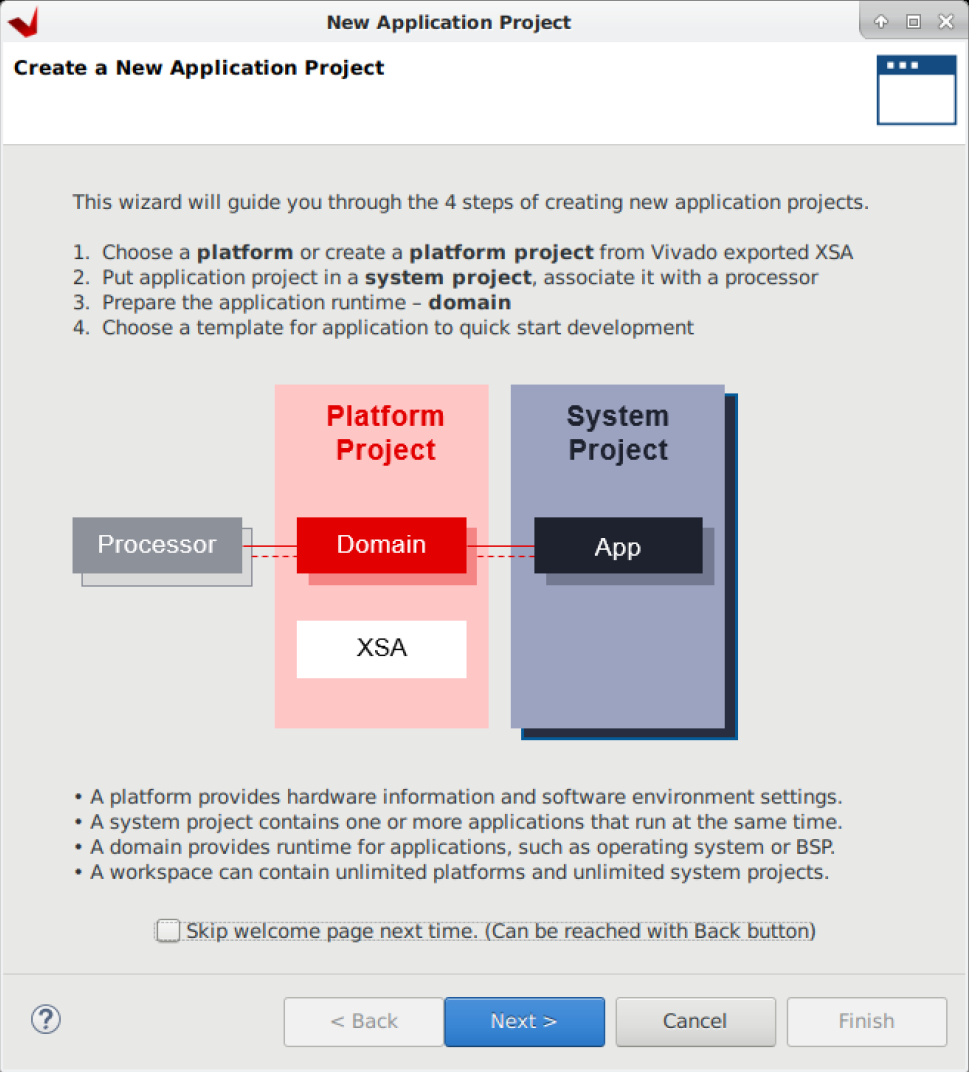
Click Next > in the first window
-
Select
xilinx_vck5000_gen4x8_qdma_2_202220_1platform and click Next >If you do not see this platform, check you followed the lab set up instructions to set the
PLATFORM_REPO_PATHSvariable.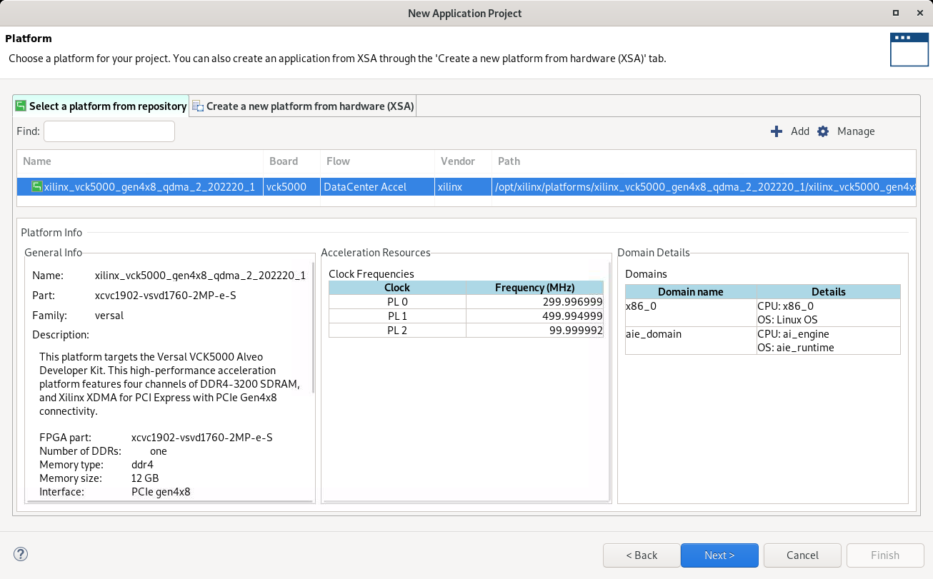
-
Name the project
aie_vadd, and select the ai_engine domain then click Next >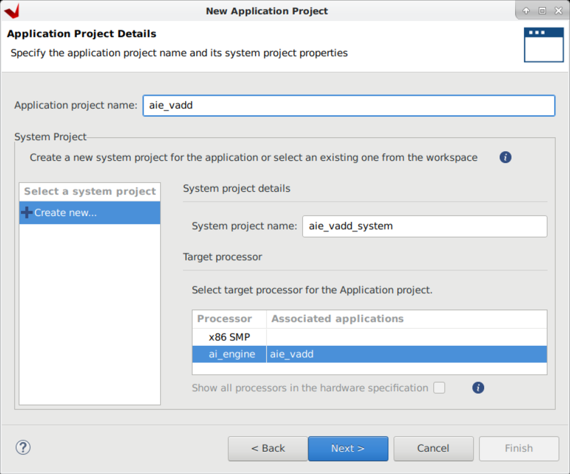
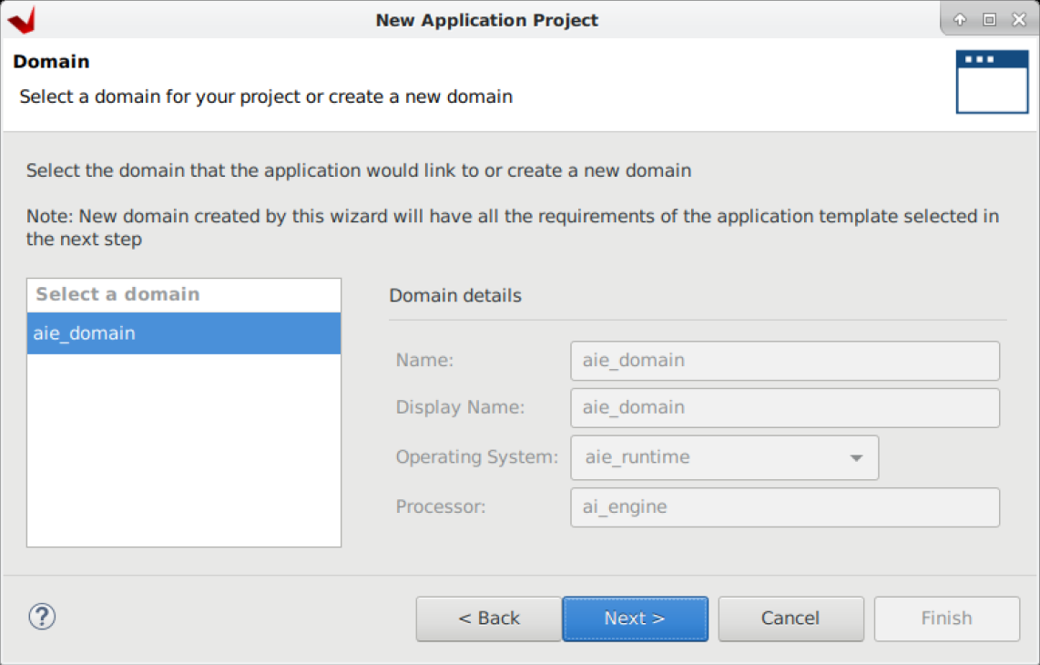
-
Confirm that the domain is aie_domain then click Next >
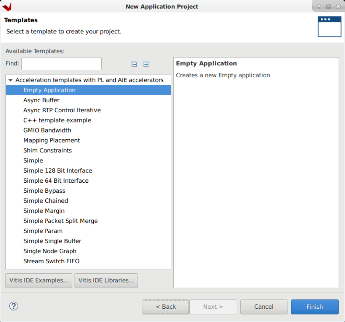
-
Select Empty Application in the Templates window and click Finish
-
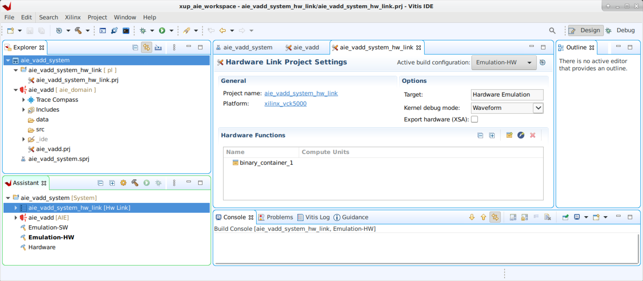
Review the Vitis IDE.
-
The Explorer view: displays a file-oriented tree view of the project folders and their associated files
-
The Assistant view: central location to view and manage the projects within the workspace. You can interact with the project settings and reports
-
Project Editor view: displays the current project, the target platform, the active build configuration and specified hardware functions. It also allows you to edit the project settings
-
Console view, presents multiple views including the command console, design guidance, project properties, logs and terminal views
For more information about the Vitis IDE check out the documentation
-
Add source code for the AI Engine domain
-
In the Explore pane, right-click
aie_vadd [ aie_domain ], then select Import Sources…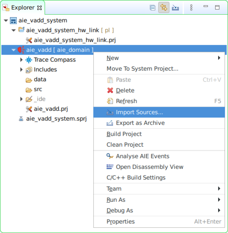
-
In the Import Source window, click Browse…, then navigate to
$HOME/xup_aie_training/sources/vadd_lab/aieand click Open. -
Tick the aie box
-
Update the field Into folder: aie_vadd
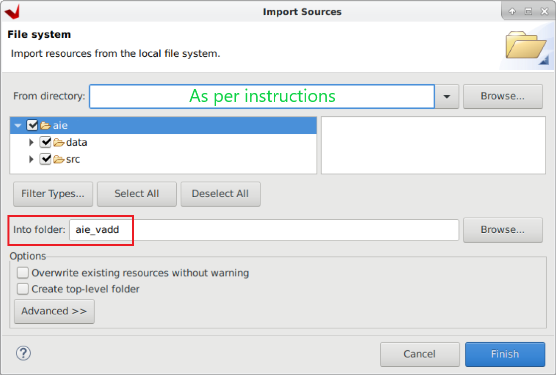
-
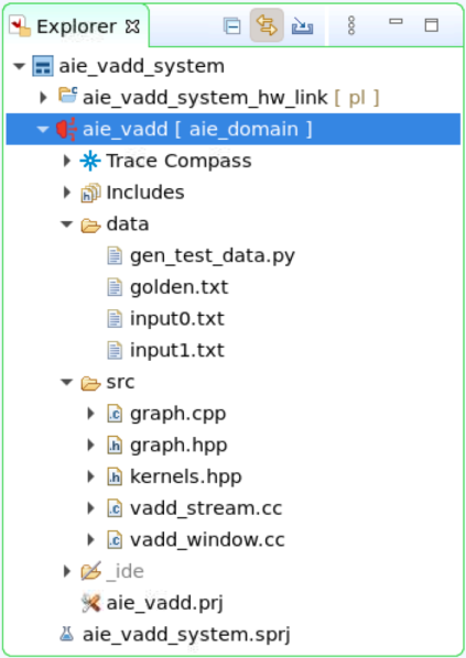
In the Explore pane, expand
aie_vadd [ aie_domain ] > dataandaie_vadd [ aie_domain ] > srcReview the source files, you can find a detailed description of the source code here
-
In the Explore pane, double-click
aie_vadd [ aie_domain ] > aie_vadd.prjThe Application Project Settings window will open
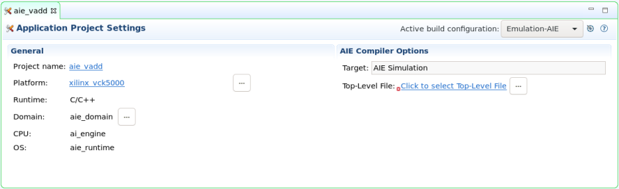
-
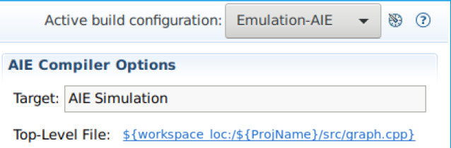
In the Application Project Settings window, select the Top-Level File

-
In the File selection window, expand
aie_vadd [ aie_domain ] > srcand select graph.cpp, then click OK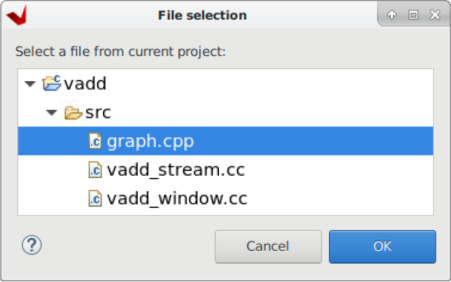
This top level file defines the testbench used for simulation.
Compile AI Engine kernel for Software Emulation
We are going to compile the AI Engine kernel and run software emulation to verify code correctness.
-
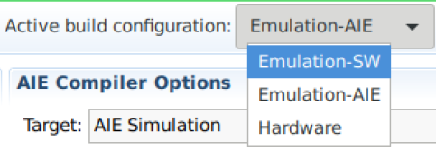
In the Application Project Settings window, set the active build configuration Emulation-SW
-
In the Explore pane, right-click on
aie_vadd [ aie_domain ]and then select Build Project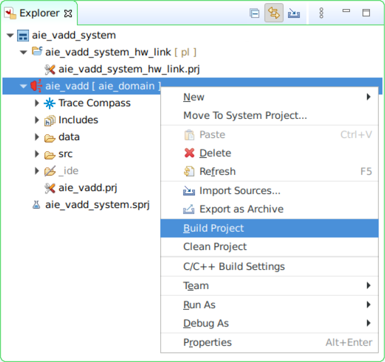
Run SW Emulation - x86 Simulation
Software emulation (x86 Simulation) uses the files in the data folder as stimuli. We will get an output file with the results.
-
In the Explore pane, right-click on
aie_vadd [ aie_domain ]and then select Run As > Launch SW Emulator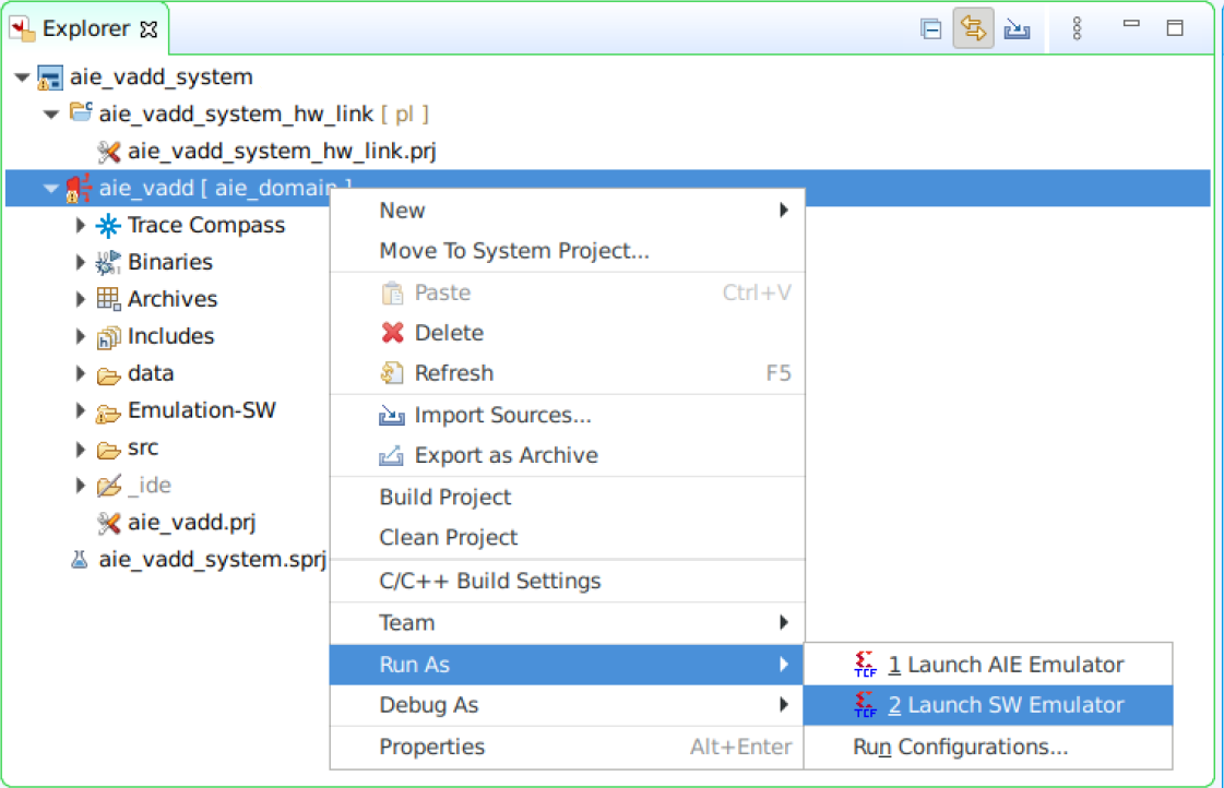
-
The Console will show the following message.
x86simulator --pkg-dir=./Work --i=.. INFO: Reading options file './Work/options/x86sim.options'. AI Engine results match golden result Simulation completed successfully returning zero -
In the Explore pane, select at the same time both
aie_vadd [ aie_domain ] > Emulation-SW > x86simulator_output > output.txtandaie_vadd [ aie_domain ] > data > golden.txt. Then, right-click on one of them and select Compare With > Each Other After Transformation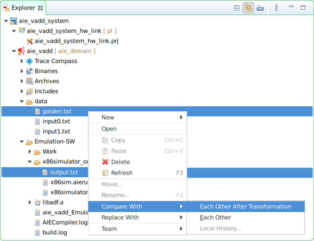
-
In the Extra transformation commands window, enter the following command to remove timestamps and to remove the extra spaces, then click OK
grep -v T {0} | sed "s/^[ \t]*//" | sed "s/[ ^t]*$//" > {0}2 && mv {0}2 {0}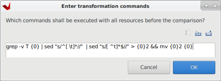
-
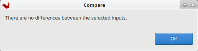
A window reporting no differences pops up, click OK to continue
Compile and run AIE Simulation
This is still a software emulation (AIE Simulation), however the simulation takes into account the actual AI Engine array architecture. The AIE Simulation also uses files as input/outputs.
-
In the Application Project Settings window, set the active build configuration Emulation-AIE
-
In the Explore pane, right-click on
aie_vadd [ aie_domain ]and then select Build ProjectThis compilation takes around 3-4 minutes
-
In the Explore pane, right-click on
aie_vadd [ aie_domain ]and then select Run As > Launch AIE Emulator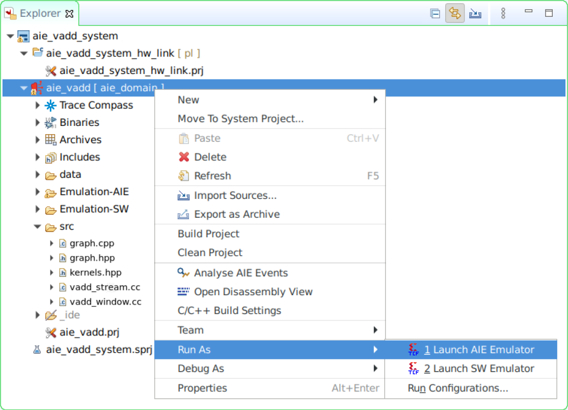
The simulation takes around 4-5 minutes
-
In the Explore pane, select at the same time both
aie_vadd [ aie_domain ] > Emulation-AIE > aiesimulator_output > output.txtandaie_vadd [ aie_domain ] > data > golden.txt. Then, right-click on one of them and select Compare With > Each Other After Transformation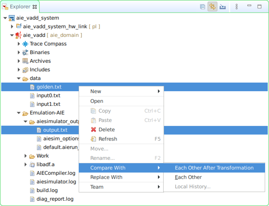
-
In the Extra transformation commands window, enter the following command to remove timestamps and to remove the extra spaces, then click OK
grep -v T {0} | sed "s/^[ \t]*//" | sed "s/[ ^t]*$//" > {0}2 && mv {0}2 {0} -
A window reporting no differences pops up, click OK to finish
Assignments for the Reader
The following assignments are optional, however they will help deepen your knowledge about the AIE programming model. No solution is provided for these assignments.
-
By default the graph instantiates the
vadd_streamkernel. However, you can also instantiate thevadd_windowkernel by commenting line 11. Comment line 11, recompile the graph and rerun the AIE. What differences do you notice in the graph? -
Make the necessary changes to include both
vadd_streamandvadd_windowkernels in thesimpleGraphNote that the text files used as stimuli cannot be reused
-
Change the plio bitwidth in the
input_plio::create()to eitherplio_64_bitsorplio_128_bits. What changes do you notice? Is it necessary to make any other changes?Note that the text files used as stimuli need to be regenerated to match the plio bitwidth, the
write_filefunction on the Python file supports this
If you are attending an in-person tutorial, you can request support from your instructor. Otherwise, open a GitHub issue
Conclusion
In this lab, you used Vitis to create a vector add running on the AI Engine. You ran both x86 and AIE simulation.
Copyright© 2023 Advanced Micro Devices