DSP Library Functions
The Xilinx® digital signal processing library (DSPLib) is a configurable library of elements that can be used to develop applications on Versal™ ACAP AI Engines. This is an Open Source library for DSP applications. The functions are captured in C++ as graph containing one or more kernels. An object of this graph class in your code can be used to access the application in question. An example design showing the use of DSP library elements is provided with this library for your reference. Although open source allows use of the kernels which capture the operational code within the library element, the use of the graph class in your graph is highly recommended. See the Using the Examples for more details.
Filters
The DSPLib contains several variants of Finite Impulse Response (FIR) filters. On the AI Engine processor, data is packetized into windows. In the case of FIRs, each window is extended by a margin so that the state of the filter at the end of the previous window may be restored before new computations begin. Therefore, to maximize performance, the window size should be set to the maximum that the system will allow, though this will lead to a corresponding increase in latency.
Note
For example, with a small window, say 32 samples, the overheads of window acquisition and release will be incurred for every 32 samples. Using a larger window will mean that a greater portion of time will be spent in active computation.
FIR filters have been categorized into classes and placed in a distinct namespace scope: xf::dsp::aie::fir, to prevent name collision in the global scope. Namespace aliasing can be utilized to shorten instantiations:
namespace dsplib = xf::dsp::aie;
Additionally, each FIR filter has been placed in a unique FIR type namespace. The available FIR filter classes and the corresponding graph entry point are listed below:
Table 1: FIR Filter Classes
| Function | Namespace and class name |
|---|---|
| Single rate, asymmetrical | dsplib::fir::sr_asym::fir_sr_asym_graph |
| Single rate, symmetrical | dsplib::fir::sr_sym::fir_sr_sym_graph |
| Interpolation asymmetrical | dsplib::fir::interpolate_asym::fir_interpolate_asym_graph |
| Decimation, halfband | dsplib::fir::decimate_hb::fir_decimate_hb_graph |
| Interpolation, halfband | dsplib::fir::interpolate_hb::fir_interpolate_hb_graph |
| Decimation, asymmetric | dsplib::fir::decimate_asym::fir_decimate_asym_graph |
| Interpolation, fractional, asymmetric | dsplib::fir::interpolate_fract_asym:: fir_interpolate_fract_asym_graph |
| Decimation, symmetric | dsplib::fir::decimate_sym::fir_decimate_sym_graph |
Conventions for Filters
All FIR filters can be configured for various types of data and coefficients. These types can be int16, int32, or float, and also real or complex. However, configurations with real data versus complex coefficients are not supported nor are configurations where the coefficents are a higher precision type than the data type. Data and coefficients must both be integer types or both be float types, as mixes are not supported.
The following table lists the supported combinations of data type and coefficient type.
Table 2: Supported Combinations of Data Type and Coefficient Type
| Data Type | |||||||
|---|---|---|---|---|---|---|---|
| Int16 | Cint16 | Int32 | Cint32 | Float | Cfloat | ||
| Coefficient type | Int16 | Supported | Supported | Supported | Supported | 3 | 3 |
| Cint16 | 1 | Supported | 1 | Supported | 3 | 3 | |
| Int32 | 2 | 2 | Supported | Supported | 3 | 3 | |
| Cint32 | 1, 2 | 2 | 1 | Supported | 3 | 3 | |
| Float | 3 | 3 | 3 | 3 | Supported | Supported | |
| Cfloat | 3 | 3 | 3 | 3 | 3 | Supported | |
|
|||||||
For all filters, the coefficient values are passed, not as template parameters, but as an array argument to the constructor for non-reloadable configurations, or to the reload function for reloadable configurations. In the case of symmetrical filters, only the first half (plus any odd centre tap) need be passed, as the remainder may be derived by symmetry. For halfband filters, only the non-zero coefficients should be entered, with the centre tap last in the array. The length of the array expected will therefore be (TP_FIR_LEN+1)/4+1, e.g. 4 non-zero tap values, including the centre tap, are expected for a halfband filter of length 11.
The following table lists parameters supported by all the FIR filters:
Table 3: Parameters Supported by FIR Filters
| Parameter Name | Type | Description | Range |
|---|---|---|---|
| TP_FIR_LEN | Unsigned int | The number of taps | 4 to 240 |
| TP_RND | Unsigned int | Round mode | 0 = truncate or floor 1 = ceiling 2 = positive infinity 3 = negative infinity 4 = symmetrical to infinity 5 = symmetrical to zero 6 = convergent to even 7 = convergent to odd |
| TP_SHIFT | Unsigned int | The number of bits to shift unscaled result down by before output. | 0 to 61 |
| TT_DATA | Typename | Data Type | int16, cint16, int32, cint32, float, cfloat |
| TT_COEFF | Typename | Coefficient type | int16, cint16, int32, cint32, float, cfloat |
| TP_INPUT_WINDOW_VSIZE | Unsigned int | The number of samples in the input window. | Must be a multiple of the number of lanes used (typically 4 or 8). No enforced range, but large windows will result in mapper errors due to excessive RAM use. |
| TP_CASC_LEN | Unsigned int | The number of cascaded kernels to use for this FIR. | 1 to 9. Defaults to 1 if not set. |
| TP_DUAL_IP | Unsigned int | Use dual inputs ports. An additional ‘in2’ input port will appear on the graph when set to 1. |
Range 0 (single input), 1 (dual input). Defaults to 0 if not set. |
| TP_USE_COEFF_RELOAD | Unsigned int | Enable reloadable coefficient feature. An additional ‘coeff’ RTP port will appear on the graph. |
0 (no reload), 1 (use reloads). Defaults to 0 if not set. |
| TP_NUM_OUTPUTS | Unsigned int | Number of fir output ports An additional ‘out2’ output port will appear on the graph when set to 2. |
1 to 2 Defaults to 1 if not set. |
| TP_API | Unsigned int | I/O interface port type | 0 = Window 1 = Stream |
Note
The number of lanes is the number of data elements that are being processed in parallel. This varies depending on the data type (i.e., number of bits in each element) and the register or bus width.
TP_API specifies if the input/output interface should be window-based or stream-based. The values supported are 0 (window API) or 1 (stream API).
Note
TP_API template parameter is currently only supported with single rate FIRs.
TP_CASC_LEN describes the number of AIE processors to split the operation over, which allows resource to be traded for higher performance. TP_CASC_LEN must be in the range 1 (default) to 9. FIR graph instance consists of TP_CASC_LEN kernels and the FIR length (TP_FIR_LEN) is divided by the requested cascade length and each kernel in the graph gets assigned a fraction of the workload. Kernels are connected with cascade ports, which pass partial accumulation products downstream until last kernel in chain produces the output.
TP_DUAL_IP is an implementation trade-off between performance and resource utilization. Symmetric FIRs may be instanced with 2 input ports to alleviate the potential for memory read contention, which would otherwise result in stall cycles and therefore lower throughput. In addition, FIRs with streaming interface may utilize the second input port to maximize the available throughput.
When set to 0, the FIR is created with a single input port.
When set to 1, two input ports will be created.
Note
when used, port:
port<input> in2;will be added to the FIR.
TP_USE_COEFF_RELOAD allows the user to select if runtime coefficient reloading should be used. When defining the parameter:
0 = static coefficients, defined in filter constructor
1 = reloadable coefficients, passed as argument to runtime function.
Note
when used, port:
port<input> coeff;will be added to the FIR.
TP_NUM_OUTPUTS sets the number of output ports to send the output data to. Supported range: 1 to 2.
For Windows API, additional output provides flexibility in connecting FIR output with multiple destinations.
Additional output out2 is an exact copy of the data of the output port out.
Stream API uses the additional output port to increase the FIR’s throughput. Please refer to Stream Output for more details.
Note
when used, port: port<output> out2; will be added to the FIR.
Streaming interface for Filters
Streaming interfaces are now supported by single rate FIRs. When TP_API is set to 1 the FIR will have stream API input and output ports. Such filters have lower latency than window API filters because there is no window to fill before execution can begin.
Note
Streaming interface is currently only supported with single rate FIRs.
Stream Output
Stream output allows computed data samples to be directly sent over the stream without the requirement for a ping-pong window buffer. As a result, memory use and latency are reduced. Furthermore, the streaming output allows data samples to be broadcast to multiple destinations.
To maximize the throughput, FIRs can be configured with 2 output stream ports. Set TP_NUM_OUTPUTS template parameter to 2, to create a FIR kernel with 2 output stream ports. In this scenario, the output data from the two streams is interleaved in chunks of 128 bits. E.g.:
- samples 0-3 to be sent over output stream 0 for cint16 data type,
- samples 4-7 to be sent over output stream 1 for cint16 data type.
Stream Input for Asymmetric FIRs
Stream input allows data samples to be directly written from the input stream to one of the Input Vector Registers without the requirement for a ping-pong window buffer. As a result, memory requirements and latency are reduced.
To maximize the throughput, Asymmetric FIRs can be configured with 2 input stream ports. Set TP_DUAL_IP to 1, to create a FIR instance with 2 input stream ports. In such a case the input data will be interleaved from the two ports to one data stream internally in 128 bit chunks, e.g.:
- samples 0-3 to be received on input stream 0 for cint16 data type,
- samples 4-7 to be received on input stream 1 for cint16 data type.
Note
Dual input streams offer no throughput gain if only single output stream would be used. Therefore, dual input streams are only supported with 2 output streams.
Note
Dual input ports offer no throughput gain if port api is windows. Therefore, dual input ports are only supported with streams and not windows.
Stream Input for Symmetric FIRs
Symmetric FIRs require access to data from 2 distinctive areas of the data stream and therefore require memory storage. In symmetric FIRs the stream input is connected to an input ping-pong window buffer through a DMA port of a Memory Module.
FFT/iFFT
The DSPLib contains one FFT/iFFT solution. This is a single channel, decimation in time (DIT) implementation. It has configurable point size, data type, forward/reverse direction, scaling (as a shift), cascade length, static/dynamic point size, window size, interface api (stream/window) and parallelism factor. Table 4 lists the template parameters used to configure the top level graph of the fft_ifft_dit_1ch_graph class.
Table 4: FFT Parameters
| Name | Type | Description | Range |
|---|---|---|---|
| TT_DATA | Typename | The input data type | cint16, cint32, cfloat |
| TT_TWIDDLE | Typename | The twiddle factor type. Determined by by TT_DATA | Set to cint16 for data type of cint16 or cint32 and cfloat for data type of cfloat. |
| TP_POINT_SIZE | Unsigned int | The number of samples in a frame to be processed | 2^N, where N is in the range 4 to 16, though the upper limit may be constrained by device resources. |
| TP_FFT_NIFFT | Unsigned int | Forward or reverse transform | 0 (IFFT) or 1 (FFT). |
| TP_SHIFT | Unsigned int int | The number of bits to shift unscaled result down by before output | 0 to 61 |
| TP_CASC_LEN | Unsigned int | The number of kernels the FFT will be divided over. | 1 to 12. Defaults to 1 if not set. Maximum is derived by the number of radix 2 stages required for the given point size (N where pointSize = 2^N) For float data types the max is N. For integer data types the max is CEIL(N/2). |
| TP_DYN_PT_SIZE | Unsigned int | Selects static point size or runtime dynamic point size | 0 (Static point size) 1 (dynamic point size) |
| TP_WINDOW_VSIZE | Unsigned int | The number of samples in the input window. | Must be a multiple of the number of lanes used (typically 4 or 8). No enforced range, but large windows will result in mapper errors due to excessive memory usage. |
| TP_API | Unsigned int | Selects between streams and windows for I/O | 0 (windows for input and output), 1 (streams for input and output) |
| TP_PARALLEL_POWER | Unsigned int | Selects the parallelism factor as a power of 2 | 0 to 4 (1 to 16 kernel -lanes of processing) |
TT_DATA: Supports only the 3 types listed. For real-only FFT/IFFT operation, consider using the library element widget_real2complex to convert real-only data to complex and vice versa.
TT_TWIDDLE: Is entirely determined by the choice of TT_DATA.
TP_POINT_SIZE: Must be a power of 2 with a minimum value of 16. The maximum value supported by the library element is 65536, but the achievable maximum will be determined by mapping limitations. For instance, a single tile implementation can achieve a maximum of 4096, but this may require single rather than pingpong window interfaces depending on data type.
TP_SHIFT: Can be used to implement the 1/N scaling of an IFFT.
TP_CASC_LEN: Splits the FFT/IFFT operation over multiple kernels in series, with each subsequent kernel being placed on an adjacent tile. This is to achieve higher throughput.
TP_DYN_PT_SIZE: When set to static point size all data will be expected in frames of TP_POINT_SIZE data samples, though multiple frames may be input together using TP_WINDOW_VSIZE. When set to dynamic point size each _window_ must be preceeded by a 256bit header to describe the run-time parameters of that window. Note that TP_WINDOW_VSIZE described the number of samples in a window so does not include this header. The format of the header is described in Table 5. When TP_DYN_PT_SIZE =1 TP_POINT_SIZE describes the maximum point size which may be input.
Table 5: Header Format
| Field name | Location (TT_DATA sample) | Description |
|---|---|---|
| Direction | 0 (real part) | 0 (inverse FFT) 1 (forward FFT) |
| Point size (radix2 stages) | 1 (real part) | Point size described as a power of 2. E.g. 5 described a point size of 32. |
| Reserved | 2 | reserved |
| Status (output only) | 3 (real part) | 0 = legal point size, 1 = illegal point size |
The locations are set to suit TT_DATA type. That is, for TT_DATA=cint16, direction is described in the first cint16 (real part) of the 256 bit header and point size is described in the real part of the second cint16 value. Similarly, for TT_DATA=cint32, the real part of the first cint32 value in the header holds the direction field and the second cint32 value’s real part holds the Point size (radix2) field.
Note that for TT_DATA=cfloat, the values in the header are expected as cfloat and are value-cast (not reinterpret-cast) to integers internally. The output window also has a header. This is copied from the input header except for the status field, which is inserted. The status field is ignored on input. If an illegal point size is entered, the output header will have this field set to a non-zero value and the remainder of the output window is undefined.
TP_WINDOW_VSIZE: Describes the number of data samples in the supplied window. If stream input is selected, an FFT operation will not begin until this number of samples has been input. TP_WINDOW_VSIZE does not include the 256 bit header when dynamic point size is used. TP_WINDOW_VSIZE is intended to improve performance for small point sizes by incurring the kernel acquisition and release overheads only once per window rather than once per frame of data.
TP_API: Selects between window (0) and stream (1) input/output. When set to 1, the FFT will have 2 stream port per subframe processor so as to maximize performance. Samples must be input to each stream in turn. E.g. with TP_PARALLEL_POWER=2 there will be 8 stream inputs. Samples 0 to 7 must be input one to each port, followed by samples 8 to 15, so port(0) will receive samples 0, 8, 16, etc. On output, each stream will output a splice of the overall frame. So in the above example, output port(0) will output samples 0 to TP_POINT_SIZE/8-1.
TP_PARALLEL_POWER: If greater than 0, TP_CASC_LEN applies to the subframe FFT rather than the FFT as a whole. For instance, with TP_POINT_SIZE=16384 and TP_PARALLEL_POWER = 3 there will be 8 subframe FFTs each of point size 2048. The TP_CASC_LEN in this case would be limited to 6 for integer TT_DATA types and 11 for TT_DATA = cfloat.
TP_PARALLEL_POWER is intended to improve performance and also allow support of point sizes beyond the limitations of a single tile. Diagram Figure 2: Applying Design Constraints shows an example graph with TP_PARALLEL_POWER set to 2. This results in 4 subframe processors in parallel each performing an FFT of N/2^TP_PARALLEL_POWER point size. These subframe outputs are then combined by TP_PARALLEL_POWER stages of radix2 to create the final result. The order of samples is described in the note for TP_API above.
Scaling
This FFT implementation does not implement the 1/N scaling of an IFFT. Internally, for cint16 and cint32 data, an internal data type of cint32 is used. After each rank, the values are scaled by only enough to normalize the bit growth caused by the twiddle multiplication (i.e., 15 bits). Distortion caused by saturation will be possible for large point sizes and large values when the data type is cint32.
In the case of TP_PARALLEL_POWER > 0 for cint16, scaling is applied at the end of the subframe processor and in each radix2 combiner stage so that cint16 is the data type used for internal streams for maximal performance. In this case, TP_SHIFT-TP_PARALLEL_POWER is applied as the TP_SHIFT value to each subframe processor and a TP_SHIFT of 1 is applied in each radix2 combiner stage. Better noise performance may be achieved at the expense of throughput by using TT_DATA=cint32.
No scaling is applied at any point when the data type is cfloat. Setting TP_SHIFT to any value other than 0 when TT_DATA is cfloat will result in an error.”
The graph entry point is the following:
xf::dsp::aie::fft::fft_ifft_dit_1ch_graph
Constraints
The FFT design has large memory requirements for data buffering and twiddle storage. Constraints may be necessary to fit a design or to achieve high performance, such as ensuring FFT kernels do not share tiles with other FFT kernels or user kernels. To apply constraints you must know the instance names of the internal graph hierarchy of the FFT. See Figure 2: Applying Design Constraints below.
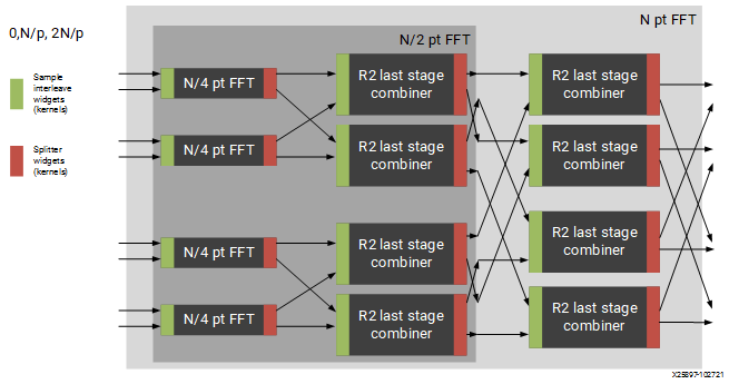
Figure 2: Applying Design Constraints
The FFT class is implemented as a recursion of the top level to implement the parallelism. The instance names of each pair of subgraphs in the recursion are FFTsubframe(0) and FFTsubframe(1). In the final level of recursion, the FFT graph will contain an instance of either FFTwinproc (for TP_API = 0) or FFTstrproc (when TP_API=1). Within this level there is an array of kernels called m_fftKernels which will have TP_CASC_LEN members.
The stream to window conversion kernels on input and output to the fft subframes are at the same level as m_fftKernels and are called m_inWidgetKernel and m_outWidgetKernel respectively. Each level of recursion will also contain an array of radix2 combiner kernels and associated stream to window conversion kernels. These are seen as a column of kernels in the above figure. Their instance names are m_r2Comb[] for the radix2 combiners and m_combInKernel[] and m_combOutKernel[] for the input and output widget kernels respectively.
Examples of constraints: For TP_PARALLEL_POWER=2, to set the runtime ratio of the 3rd of 4 subframe FFTs, the constraint could look like this:
Runtime<ratio>(myFFT.FFTsubframe[1].FFTsubframe[0].FFTstrproc.m_kernels[0]) = 0.9; //where myFFT is the instance name of the FFT in your design.
For the same example, to ensure that the second radix2 combiner kernel in the first column of combiners and its input widget do not share a tile, the constraint could look like this:
not_equal(location<kernel>(myFFT.FFTsubframe[0].m_combInKernel[1]),location<kernel>( myFFT.FFTsubframe[0].m_r2Comb[1]));
Matrix Multiply
The DSPLib contains one Matrix Multiply/GEMM (GEneral Matrix Multiply) solution. The gemm has two input ports connected to two windows of data. The inputs are denoted as Matrix A (inA) and Matrix B (inB). Matrix A has a template parameter TP_DIM_A to describe the number of rows of A. The number of columns of inA must be equal to the number of rows of inB. This is denoted with the template parameter TP_DIM_AB. The number of columns of B is denoted by TP_DIM_B.
An output port connects to a window, where the data for the output matrix will be stored. The output matrix will have rows = inA rows (TP_DIM_A) and columns = inB (TP_DIM_B) columns. The data type of both input matrices can be configured and the data type of the output is derived from the inputs.
Table 6: Matrix Multiply Parameters
| Name | Type | Description | Range |
|---|---|---|---|
| TT_DATA_A | Typename | The input data type | int16, cint16, int32, cint32, float, cfloat |
| TT_DATA_B | Typename | The input data type | int16, cint16, int32, cint32, float, cfloat |
| TP_DIM_A | Unsigned int | The number of elements along the unique dimension (rows) of Matrix A | |
| TP_DIM_AB | Unsigned int | The number of elements along the common dimension of Matrix A (columns) and Matrix B (rows) | |
| TP_DIM_B | Unsigned int | The number of elements along the unique dimension (rows) of Matrix B | |
| TP_SHIFT | Unsigned int | power of 2 shift down applied to the unscaled result of product terms before each output | In range 0 to 61 |
| TP_RND | Unsigned int | Round mode | 0 = truncate or floor 1 = ceiling 2 = positive infinity 3 = negative infinity 4 = symmetrical to infinity 5 = symmetrical to zero 6 = convergent to even 7 = convergent to odd |
| TP_DIM_A_LEADING | Unsigned int | The scheme in which the data for matrix A should be stored in memory | ROW_MAJOR = 0 COL_MAJOR = 1 |
| TP_DIM_B_LEADING | Unsigned int | The scheme in which the data for matrix B should be stored in memory | ROW_MAJOR = 0 COL_MAJOR = 1 |
| TP_DIM_OUT_LEADING | Unsigned int | The scheme in which the data for output matrix should be stored in memory | ROW_MAJOR = 0 COL_MAJOR = 1 |
| TP_ADD_TILING_A | Unsigned int | Option to add an additional kernel to rearrange matrix samples | 0 = rearrange externally to the graph 1 = rearrange internally within the graph. Adds a tiling kernel to design. |
| TP_ADD_TILING_B | Unsigned int | Option to add an additional kernel to rearrange matrix samples | 0 = rearrange externally to the graph 1 = rearrange internally within the graph. Adds a tiling kernel to design. |
| TP_ADD_DETILING_OUT | Unsigned int | Option to add an additional kernel to rearrange matrix samples | 0 = rearrange externally to the graph 1 = rearrange internally within the graph. Adds a tiling kernel to design. |
| TP_WINDOW_VSIZE_A | Unsigned int | The number of samples in the input window for Matrix A | Must be of size TP_DIM_A* TP_DIM_AB*N has a default value of TP_DIM_A* TP_DIM_AB (N=1) |
| TP_WINDOW_VSIZE_B | Unsigned int | The number of samples in the input window for Matrix B | Must be of size TP_DIM_B* TP_DIM_AB*M has a default value of TP_DIM_B* TP_DIM_AB (M=1) |
| TP_CASC_LEN | Unsigned int | The number of AIE tiles to split the operation into | Defaults to 1 if not set. |
Input matrices are processed in distinct blocks. Matrix elements must be rearranged into a specific pattern.
The following table demonstrates how a 16x16 input matrix should be rearranged into a 4x4 tiling pattern.
Note
Indices are quoted assuming a row major matrix. A column major matrix would be the transpose of the table below.
Table 7: Matrix Multiply 4x4 tiling pattern
| Tile Col 0 | Tile Col 1 | Tile Col 2 | Tile Col 3 | |||||||||||||
|---|---|---|---|---|---|---|---|---|---|---|---|---|---|---|---|---|
| Tile Row 0 | 0 | 1 | 2 | 3 | 4 | 5 | 6 | 7 | 8 | 9 | 10 | 11 | 12 | 13 | 14 | 15 |
| 16 | 17 | 18 | 19 | 20 | 21 | 22 | 23 | 24 | 25 | 26 | 27 | 28 | 29 | 30 | 31 | |
| 32 | 33 | 34 | 35 | 36 | 37 | 38 | 39 | 40 | 41 | 42 | 43 | 44 | 45 | 46 | 47 | |
| 48 | 49 | 50 | 51 | 52 | 53 | 54 | 55 | 56 | 57 | 58 | 59 | 60 | 61 | 62 | 63 | |
| Tile Row 1 | 64 | 65 | 66 | 67 | 68 | 69 | 70 | 71 | 72 | 73 | 74 | 75 | 76 | 77 | 78 | 79 |
| 80 | 81 | 82 | 83 | 84 | 85 | 86 | 87 | 88 | 89 | 90 | 91 | 92 | 93 | 94 | 95 | |
| 96 | 97 | 98 | 99 | 100 | 101 | 102 | 103 | 104 | 105 | 106 | 107 | 108 | 109 | 110 | 111 | |
| 112 | 113 | 114 | 115 | 116 | 117 | 118 | 119 | 120 | 121 | 122 | 123 | 124 | 125 | 126 | 127 | |
| Tile Row 2 | 128 | 129 | 130 | 131 | 132 | 133 | 134 | 135 | 136 | 137 | 138 | 139 | 140 | 141 | 142 | 143 |
| 144 | 145 | 146 | 147 | 148 | 149 | 150 | 151 | 152 | 153 | 154 | 155 | 156 | 157 | 158 | 159 | |
| 160 | 161 | 162 | 163 | 164 | 165 | 166 | 167 | 168 | 169 | 170 | 171 | 172 | 173 | 174 | 175 | |
| 176 | 177 | 178 | 179 | 180 | 181 | 182 | 183 | 184 | 185 | 186 | 187 | 188 | 189 | 190 | 191 | |
| Tile Row 3 | 192 | 193 | 194 | 195 | 196 | 197 | 198 | 199 | 200 | 201 | 202 | 203 | 204 | 205 | 206 | 207 |
| 208 | 209 | 210 | 211 | 212 | 213 | 214 | 215 | 216 | 217 | 218 | 219 | 220 | 221 | 222 | 223 | |
| 224 | 225 | 226 | 227 | 228 | 229 | 230 | 231 | 232 | 233 | 234 | 235 | 236 | 237 | 238 | 239 | |
| 240 | 241 | 242 | 243 | 244 | 245 | 246 | 247 | 248 | 249 | 250 | 251 | 252 | 253 | 254 | 255 | |
This is stored contiguously in memory like:
0, 1, 2, 3, 16, 17, 18, 19, 32, 33, 34, 35, 48, 49, 50, 51, 4, 5, 6, 7, 20, 21, 22, 23, 36, 37, 38, 39, 52, 53, 54, 55, 8, 9, 10, 11, 24, 25, 26, 27, 40, 41, 42, 43, 56, 57, 58, 59, 12, 13, 14, 15, 28, 29, 30, 31, 44, 45, 46, 47, 60, 61, 62, 63, 64, 65, 66, 67, 80, 81, 82, 83, 96, 97, 98, 99, 112, 113, 114, 115, … , 204, 205, 206, 207, 220, 221, 222, 223, 236, 237, 238, 239, 252, 253, 254, 255
The following table demonstrates how a 16x16 input matrix should be rearranged into a 4x2 tiling pattern.
Table 8: Matrix Multiply 4x2 tiling pattern
| Tile Col 0 | Tile Col 1 | Tile Col 2 | Tile Col 3 | Tile Col 4 | Tile Col 5 | Tile Col 6 | Tile Col 7 | |||||||||
|---|---|---|---|---|---|---|---|---|---|---|---|---|---|---|---|---|
| Tile Row 0 | 0 | 1 | 2 | 3 | 4 | 5 | 6 | 7 | 8 | 9 | 10 | 11 | 12 | 13 | 14 | 15 |
| 16 | 17 | 18 | 19 | 20 | 21 | 22 | 23 | 24 | 25 | 26 | 27 | 28 | 29 | 30 | 31 | |
| 32 | 33 | 34 | 35 | 36 | 37 | 38 | 39 | 40 | 41 | 42 | 43 | 44 | 45 | 46 | 47 | |
| 48 | 49 | 50 | 51 | 52 | 53 | 54 | 55 | 56 | 57 | 58 | 59 | 60 | 61 | 62 | 63 | |
| Tile Row 1 | 64 | 65 | 66 | 67 | 68 | 69 | 70 | 71 | 72 | 73 | 74 | 75 | 76 | 77 | 78 | 79 |
| 80 | 81 | 82 | 83 | 84 | 85 | 86 | 87 | 88 | 89 | 90 | 91 | 92 | 93 | 94 | 95 | |
| 96 | 97 | 98 | 99 | 100 | 101 | 102 | 103 | 104 | 105 | 106 | 107 | 108 | 109 | 110 | 111 | |
| 112 | 113 | 114 | 115 | 116 | 117 | 118 | 119 | 120 | 121 | 122 | 123 | 124 | 125 | 126 | 127 | |
| Tile Row 2 | 128 | 129 | 130 | 131 | 132 | 133 | 134 | 135 | 136 | 137 | 138 | 139 | 140 | 141 | 142 | 143 |
| 144 | 145 | 146 | 147 | 148 | 149 | 150 | 151 | 152 | 153 | 154 | 155 | 156 | 157 | 158 | 159 | |
| 160 | 161 | 162 | 163 | 164 | 165 | 166 | 167 | 168 | 169 | 170 | 171 | 172 | 173 | 174 | 175 | |
| 176 | 177 | 178 | 179 | 180 | 181 | 182 | 183 | 184 | 185 | 186 | 187 | 188 | 189 | 190 | 191 | |
| Tile Row 3 | 192 | 193 | 194 | 195 | 196 | 197 | 198 | 199 | 200 | 201 | 202 | 203 | 204 | 205 | 206 | 207 |
| 208 | 209 | 210 | 211 | 212 | 213 | 214 | 215 | 216 | 217 | 218 | 219 | 220 | 221 | 222 | 223 | |
| 224 | 225 | 226 | 227 | 228 | 229 | 230 | 231 | 232 | 233 | 234 | 235 | 236 | 237 | 238 | 239 | |
| 240 | 241 | 242 | 243 | 244 | 245 | 246 | 247 | 248 | 249 | 250 | 251 | 252 | 253 | 254 | 255 | |
This is stored contiguously in memory like:
0, 1, 16, 17, 32, 33, 48, 49, 2, 3, 18, 19, 34, 35, 50, 51, …, 206, 207, 222, 223, 238, 239, 254, 255
Multiplying a 16x16 matrix (with 4x4 tiling) with a 16x16 matrix (with 4x2 tiling) will result in a 16x16 matrix with 4x2 tiling.
The following table specifies the tiling scheme used for a given data type combination and the corresponding output data type:
Table 9: Matrix Multiply tiling pattern combination
| Input Type Combination | Tiling Scheme | Output Type | ||
|---|---|---|---|---|
| A | B | A | B | |
| int16 | int16 | 4x4 | 4x4 | int16 |
| int16 | cint16 | 4x2 | 2x2 | cint16 |
| int16 | int32 | 4x2 | 2x2 | int32 |
| int16 | cint32 | 2x4 | 4x2 | cint32 |
| cint16 | int16 | 4x4 | 4x2 | cint16 |
| cint16 | cint16 | 4x4 | 4x2 | cint16 |
| cint16 | int32 | 4x4 | 4x2 | cint32 |
| cint16 | cint32 | 2x2 | 2x2 | cint32 |
| int32 | int16 | 4x4 | 4x2 | int32 |
| int32 | int32 | 4x4 | 4x2 | int32 |
| int32 | cint16 | 4x4 | 4x2 | cint32 |
| int32 | cint32 | 2x2 | 2x2 | cint32 |
| cint32 | int16 | 2x4 | 4x2 | cint32 |
| cint32 | cint16 | 2x2 | 2x2 | cint32 |
| cint32 | int32 | 2x2 | 2x2 | cint32 |
| cint32 | cint32 | 2x2 | 2x2 | cint32 |
| float | float | 4x4 | 4x2 | float |
| float | cfloat | 2x4 | 4x2 | cfloat |
| cfloat | float | 2x4 | 4x2 | cfloat |
| cfloat | cfloat | 4x2 | 2x2 | cfloat |
The parameters TP_ADD_TILING_A, TP_ADD_TILING_B, and TP_ADD_DETILING_OUT control the inclusion of an additional pre-processing / post-processing kernel to perform the required data data storage re-ordering. When used with TP_DIM_A_LEADING, TP_DIM_B_LEADING, or TP_DIM_OUT_LEADING, the matrix is also transposed in the tiling kernel.
If the additional kernels are not selected, then the matrix multiply kernels assume incoming data is in the correct format, as specified above. When using the TP_CASC_LEN parameter, the matrix multiply operation is split across TP_DIM_AB and processed in a TP_CASC_LEN number of kernels. The accumulated partial results of each kernel are passed down the cascade port to the next kernel in the cascade chain until the final kernel provides the expected output. Cascade connections are made internally to the matrix multiply graph.
Each AI Engine kernel in the array is given a sub-matrix, so the interface to the graph is an array of ports for both A and B.
Input Matrix A (16x16 - 4x4 Tile - Cascade Length 2):
Table 10: Input Matrix A (16x16 - 4x4 Tile - Cascade Length 2)
| AIE 0 | AIE 1 | |||||||||||||||
|---|---|---|---|---|---|---|---|---|---|---|---|---|---|---|---|---|
| Tile Col 0 | Tile Col 1 | Tile Col 2 | Tile Col 3 | |||||||||||||
| Tile Row 0 | 0 | 1 | 2 | 3 | 4 | 5 | 6 | 7 | 8 | 9 | 10 | 11 | 12 | 13 | 14 | 15 |
| 16 | 17 | 18 | 19 | 20 | 21 | 22 | 23 | 24 | 25 | 26 | 27 | 28 | 29 | 30 | 31 | |
| 32 | 33 | 34 | 35 | 36 | 37 | 38 | 39 | 40 | 41 | 42 | 43 | 44 | 45 | 46 | 47 | |
| 48 | 49 | 50 | 51 | 52 | 53 | 54 | 55 | 56 | 57 | 58 | 59 | 60 | 61 | 62 | 63 | |
| Tile Row 1 | 64 | 65 | 66 | 67 | 68 | 69 | 70 | 71 | 72 | 73 | 74 | 75 | 76 | 77 | 78 | 79 |
| 80 | 81 | 82 | 83 | 84 | 85 | 86 | 87 | 88 | 89 | 90 | 91 | 92 | 93 | 94 | 95 | |
| 96 | 97 | 98 | 99 | 100 | 101 | 102 | 103 | 104 | 105 | 106 | 107 | 108 | 109 | 110 | 111 | |
| 112 | 113 | 114 | 115 | 116 | 117 | 118 | 119 | 120 | 121 | 122 | 123 | 124 | 125 | 126 | 127 | |
| Tile Row 2 | 128 | 129 | 130 | 131 | 132 | 133 | 134 | 135 | 136 | 137 | 138 | 139 | 140 | 141 | 142 | 143 |
| 144 | 145 | 146 | 147 | 148 | 149 | 150 | 151 | 152 | 153 | 154 | 155 | 156 | 157 | 158 | 159 | |
| 160 | 161 | 162 | 163 | 164 | 165 | 166 | 167 | 168 | 169 | 170 | 171 | 172 | 173 | 174 | 175 | |
| 176 | 177 | 178 | 179 | 180 | 181 | 182 | 183 | 184 | 185 | 186 | 187 | 188 | 189 | 190 | 191 | |
| Tile Row 3 | 192 | 193 | 194 | 195 | 196 | 197 | 198 | 199 | 200 | 201 | 202 | 203 | 204 | 205 | 206 | 207 |
| 208 | 209 | 210 | 211 | 212 | 213 | 214 | 215 | 216 | 217 | 218 | 219 | 220 | 221 | 222 | 223 | |
| 224 | 225 | 226 | 227 | 228 | 229 | 230 | 231 | 232 | 233 | 234 | 235 | 236 | 237 | 238 | 239 | |
| 240 | 241 | 242 | 243 | 244 | 245 | 246 | 247 | 248 | 249 | 250 | 251 | 252 | 253 | 254 | 255 | |
Input Matrix B (16x16 - 4x2 Tile - Cascade Length 2):
Table 11: Input Matrix B (16x16 - 4x2 Tile - Cascade Length 2)
| Tile Col 0 | Tile Col 1 | Tile Col 2 | Tile Col 3 | Tile Col 4 | Tile Col 5 | Tile Col 6 | Tile Col 7 | ||||||||||
|---|---|---|---|---|---|---|---|---|---|---|---|---|---|---|---|---|---|
| AIE 0 | Tile Row 0 | 0 | 1 | 2 | 3 | 4 | 5 | 6 | 7 | 8 | 9 | 10 | 11 | 12 | 13 | 14 | 15 |
| 16 | 17 | 18 | 19 | 20 | 21 | 22 | 23 | 24 | 25 | 26 | 27 | 28 | 29 | 30 | 31 | ||
| 32 | 33 | 34 | 35 | 36 | 37 | 38 | 39 | 40 | 41 | 42 | 43 | 44 | 45 | 46 | 47 | ||
| 48 | 49 | 50 | 51 | 52 | 53 | 54 | 55 | 56 | 57 | 58 | 59 | 60 | 61 | 62 | 63 | ||
| Tile Row 1 | 64 | 65 | 66 | 67 | 68 | 69 | 70 | 71 | 72 | 73 | 74 | 75 | 76 | 77 | 78 | 79 | |
| 80 | 81 | 82 | 83 | 84 | 85 | 86 | 87 | 88 | 89 | 90 | 91 | 92 | 93 | 94 | 95 | ||
| 96 | 97 | 98 | 99 | 100 | 101 | 102 | 103 | 104 | 105 | 106 | 107 | 108 | 109 | 110 | 111 | ||
| 112 | 113 | 114 | 115 | 116 | 117 | 118 | 119 | 120 | 121 | 122 | 123 | 124 | 125 | 126 | 127 | ||
| AIE 1 | Tile Row 2 | 128 | 129 | 130 | 131 | 132 | 133 | 134 | 135 | 136 | 137 | 138 | 139 | 140 | 141 | 142 | 143 |
| 144 | 145 | 146 | 147 | 148 | 149 | 150 | 151 | 152 | 153 | 154 | 155 | 156 | 157 | 158 | 159 | ||
| 160 | 161 | 162 | 163 | 164 | 165 | 166 | 167 | 168 | 169 | 170 | 171 | 172 | 173 | 174 | 175 | ||
| 176 | 177 | 178 | 179 | 180 | 181 | 182 | 183 | 184 | 185 | 186 | 187 | 188 | 189 | 190 | 191 | ||
| Tile Row 3 | 192 | 193 | 194 | 195 | 196 | 197 | 198 | 199 | 200 | 201 | 202 | 203 | 204 | 205 | 206 | 207 | |
| 208 | 209 | 210 | 211 | 212 | 213 | 214 | 215 | 216 | 217 | 218 | 219 | 220 | 221 | 222 | 223 | ||
| 224 | 225 | 226 | 227 | 228 | 229 | 230 | 231 | 232 | 233 | 234 | 235 | 236 | 237 | 238 | 239 | ||
| 240 | 241 | 242 | 243 | 244 | 245 | 246 | 247 | 248 | 249 | 250 | 251 | 252 | 253 | 254 | 255 | ||
The graph entry point is the following:
xf::dsp::aie::blas::matrix_mult::matrix_mult_graph
Find a full list of descriptions and parameters in the API Reference Overview.
Connections to the cascade ports can be made as follows:
for (int i = 0 ; i < P_CASC_LEN; i++) {
    connect<>(inA[i], mmultGraph.inA[i]);
    connect<>(inB[i], mmultGraph.inB[i]);
}
connect<>(mmultGraph.out, out);
Widgets
Widget API Cast
The DSPLib contains a Widget API Cast solution, which provides flexibilty when connecting other kernels. This component is able to change the stream interface to window interface and vice-versa. It may be configured to read two input stream interfaces and interleave data onto an output window interface. In addition, multiple copies of output window may be configured to allow extra flexibility when connecting to further kernels.
Table 12: Widget API Cast Parameters
| Name | Type | Description | Range |
|---|---|---|---|
| TT_DATA | Typename | Data Type | int16, cint16, int32, cint32, float, cfloat |
| TP_IN_API | Unsigned int | The input interface type | 0 = window, 1 = stream |
| TP_OUT_API | Typename int | The output interface type | 0 = window, 1 = stream |
| TP_NUM_INPUTS | Unsigned int | The number of input stream interfaces to be processed | 1 - 2 |
| TP_WINDOW_VSIZE | Unsigned int | The number of samples in the input window | Must be a multiple of the number of lanes used (typically 4 or 8). No enforced range, but large windows will result in mapper errors due to excessive RAM use. |
| TP_NUM_OUTPUT_CLONES | Unsigned int | The number of output window ports to write the input data to. | 1 - 4 |
| TP_PATTERN | Unsigned int | The pattern of interleave by which samples from each of 2 streams are arranged into the destination window, or from the input window to dual output streams. | 0 - 2 |
Note
The number of lanes is the number of data elements that are being processed in parallel. This varies depending on the data type (i.e., number of bits in each element) and the register or bus width.
The graph entry point is the following:
xf::dsp::aie::widget::api_cast::widget_api_cast_graph
Widget Real to Complex
The DSPLib contains a Widget Real to Complex solution, which provides a utility to convert real data to complex or vice versa.
Table 13: Widget Real to Complex Parameters
| Name | Type | Description | Range |
|---|---|---|---|
| TT_DATA | Typename | Data Type | int16, cint16, int32, cint32, float, cfloat |
| TT_OUT_DATA | Typename | Data Type | int16, cint16, int32, cint32, float, cfloat |
| TP_WINDOW_VSIZE | Unsigned int | The number of samples in the input window | Must be a multiple of the number of lanes used (typically 4 or 8). No enforced range, but large windows will result in mapper errors due to excessive RAM use. |
Note
The number of lanes is the number of data elements that are being processed in parallel. This varies depending on the data type (i.e., number of bits in each element) and the register or bus width.
The graph entry point is the following:
xf::dsp::aie::widget::api_cast::widget_api_cast_graph
DDS / Mixer
The DSPLib contains a DDS and Mixer solution.
In DDS Only mode, there is a single output port that contains the sin/cosine components corresponding to the programmed phase increment. The phase increment is a fixed uint32 value provided as a constructor argument, where 2^31 corresponds to Pi (180 degrees phase increment). The number of samples sent through the output port is determined by the TP_INPUT_WINDOW_SIZE parameter. The output port can be a window interface or a stream interface depending on the use of TP_API.
Mixer inputs are enabled with the TP_MIXER_MODE template parameter. There are two modes that have the mixer functionality enabled. In MIXER_MODE_1, a single input port is exposed and the input samples are complex multiplied by the DDS output for the given phase increment. In MIXER_MODE_2, two input ports are exposed for multi-carrier operation, with the first behaving as in MIXER_MODE_1, and the second input port getting complex multiplied with the complex conjugate of the DDS signal then accumulated to the result of the first complex multiply operation.
Table 14: DDS / Mixer Parameters
| Name | Type | Description | Range |
|---|---|---|---|
| TT_DATA | Typename | Data Type | cint16 |
| TP_INPUT_WINDOW_VSIZE | Unsigned int | The number of samples to process each iteration | Must be a multiple of the number of lanes used (typically 4 or 8). No enforced range, but large windows will result in mapper errors due to excessive RAM use. |
| TP_MIXER_MODE | Unsigned int | Mode of operation | 0 = DDS Only 1 = Single input mixer 2 = Two input mixer |
| TP_API | Unsigned int | I/O interface port type | 0 = Window 1 = Stream |