Software Architecture of the Platform
Introduction
This section describes software components involved in the design and their relation with each other. The application requires the hardware platform as described in Hardware Architecture of the Platform for the stack explained in this section to work.
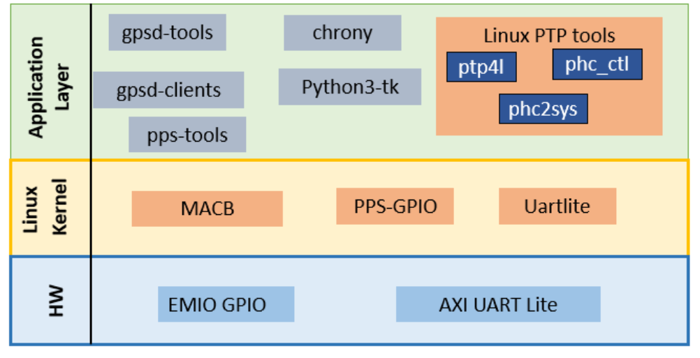
The following diagram illustrates the top-level architecture and the arrangement of various software components:

Operating System: Xilinx Linux kernel + Ubuntu env
Drivers:
Uart lite
PPS-GPIO
Applications
gpsd
chrony
Linux PTP utilities for clock sync
pps-tools
The details of each individual component can be obtained though the reference at the end of this section. The scope of this document is with respect to what is being demonstrated through the example application.
Gpsd
Gpsd is a service Daemon for establishing the connection to the external GPS Receiver. This Daemon is configured to read and process UBX protocol messages through the Uart interface on the master node. The results are provided via an IPC shared memory buffer.
Chrony
Chrony is a daemon for synchronization of the system clock. It can synchronize the clock with NTP servers and reference clocks (for example, a GPS receiver). It is configured to work with shared memory segment and also process the PPS (/dev/ppsX) interface.
Linux ptp utilities:
Phc2sys
phc2sys establishes the synchronization between the PHC and system clocks ,the actual synchronization direction depends on the role of the node.
ptp4l
ptp4l implements the PTP network protocol and aligns the PHC clocks on the both master and slave.
pps-tools
It is a tool to monitor PPS timestamps from the pps device.
GPS-1588-PTP Application
By using this application, the system time of the embedded platform is synchronized with the GPS time using ubuntu daemons and linux-ptp utilities. The system time of the master side is distributed to the connected slaves in the network.
How Synchronization works
The synchronization starts by synchronizing the system time of the Master KR260 board with respect to the GPS time using the Network Time Protocol (NTP) daemon chrony. In this case, we have configured two sources from GPS receiver.
GPS receiver UART interface as a source of GPS time via AXI Uart lite driver.
GPS Receiver PPS input as PPS source registered as pps-gpio driver to correct the system time with respect to the high precision PPS pulse.
Using the Linux PTP tools phc2sys, the Master side GEM TSU timer is aligned with respect to the system time. In the slave side, ptp4l first synchronizes the GEM PHC with the master side PHC using PTP packets via the GEM PS ethernet interface. Following that, the slave board system clock is synchronized to the PHC clock using the phc2sys tool. Now the synchronization direction is from the PHC clock to the system clock.
Linux driver
Uart lite
This component contains the implementation of the Uart Lite component, which is the driver for the AMD UART Lite device. This UART is a minimal hardware implementation with minimal features. Most of the features, including baud rate, parity, and the number of data bits are only configurable when the hardware device is built, rather than at runtime by the software. This driver requires different compatibility string and; hence, the original device tree node is compatible string needs to be overwritten as shown below:
&axi_uartlite_0 {
      compatible = "xlnx,axi-uartlite-2.0","xlnx,xps-uartlite-1.00.a";
};
PPS-GPIO
This driver is derived from the current parallel port PPS generator and provides a PPS signal through a GPIO pin specified in the device tree. PPS stands for “pulse per second” and a PPS source is just a device that provides a high-precision signal each second so that an application can use it to adjust the system clock time.
The details of the device tree for the driver can be found in the kernel documentation at linux-xlnx.
  	pps_axi_gpio_0 {
              pinctrl-names = "default";
              gpios = <&gpio 78 0 0 >;
              compatible = "pps-gpio";
              };
References
Next Steps
Go back to the KR260 SOM GPS-1588-PTP App Start Page
Copyright (C) 2023 Advanced Micro Devices, Inc.