Memory test case description
The goal of this test case is to check communications between the memory CUs and memories available:
On the card: Typically, DDRs.
In the FPGA: For example, HBM.
On the host (with PCIe slave-bridge): Slave-bridge provides access between the memory CU and host memory (HOST) via PCIe. The memory CU can use the host memory the same way it currently uses the other memories.
Important
Host memory must be allocated prior being tested (see Host memory set up).
Important
For NoDMA platform, an area of allocated host memory is reserved for the Application software to access CU status register transferred from PLRAM and is not usable in the Memory test case targeting the host memory (HOST).
Note
In the DMA test case, xbtest software controls data transfers between host and memories available on the card and in the FPGA.
In the P2P CARD and P2P NVME test cases, xbtest software controls data transfers between PCIe cards.
In the Memory test case, xbtest commands the memory CUs to transfer data between the CU and their associated memories located on the card, in the FPGA, or on the host.
The Memory test case includes the following features:
All memories are tested in parallel.
All memories of a type (for example DDR, HBM, or HOST) are tested with the same sequence (see Memory CU types).
Data integrity is checked using PRBS31 generator/checker within the CU.
Write and read bandwidths and latencies are measured.
Mode of data transfer is configurable. Available modes are only/alternate/simultaneous write/read.
Write/read rates, burst size, maximum number of outstanding transactions, block size and start address offset of the memory CU data transfers are configurable separately.
All transfers are performed using linear addressing.
Multiple AXI ID threads can be supported by the memory CU depending on the platform.
Test parameters
The mandatory test configuration parameters are listed below. For more information, see Memory Test JSON Members.
Important
By default, xbtest loads a valid PRBS31 data sequence in the memory before any only_rd or simultaneous_wr_rd test.
This can be disabled (disable_prewrite) and the presence of valid PRBS data in the memory can be managed manually within your test_sequence,
defining at least one only_wr test prior to the first only_rd or simultaneous_wr_rd test.
The following optional parameters may also be specified:
wr_rate: Write data transfer rate.
rd_rate: Read data transfer rate.
wr_burst_size: Write burst size.
rd_burst_size: Read burst size.
wr_outstanding: Maximum number of outstanding write transactions.
rd_outstanding: Maximum number of outstanding read transactions.
wr_block_size: Write block size.
rd_block_size: Read block size.
wr_start_addr: Write start address offset.
rd_start_addr: Read start address offset.
Important
For some memory types, the memory CU has been intentionally designed to exceed the power capacity of the card. Your server/workstation may reboot or xbtest may be interrupted if you try to use a high write or read data transfer rates. Nominal write and read data transfer rates are specified in platform definition file (see Platform definition).
Main test steps
For each test configuration, the following steps are repeated:
The test is run for at least the defined duration. The entire range of the memory is always checked, meaning that, if needed, the test duration is extended.
Every second, the Application software requests status and measurements from the CU:
Read/write bandwidths and latencies.
Data integrity status.
After the test completes, the Application software displays the measured average read/write bandwidth and latency. Bandwidths and latencies are also checked against thresholds under some conditions (see Bandwidth and latency check conditions).
Measurements
The memory CUs computes burst time and latency.
The bandwidth is computed every second by the Test software after requesting measurements from the CU.
Warning
Some platforms include safety feature such as clock throttling when the power or temperature exceed pre-defined limits (refer to the documentation for your card). If the clock throttling has been activated while doing a memory test, the memory CU measurements are impacted as they depend on expected clock frequency and the Memory test case might fail.
xbtest can detects clock throttling is on only when continuous clock has been connected to the CU.
If the memory test fails while the Power test case is running, a warning (
MEM_051) is reported to alert on potential clock throttling.
Burst time
The following sections describes the start and end point for burst time measurement, which are similar in the write and read directions. The Memory test case reports minimum, average and maximum burst time, which are not check against any thresholds.
Burst time |
Description |
Illustration |
|---|---|---|
Write |
The write burst time is measured for a given burst using the following:
|
The following figure represents the write burst time measurement: 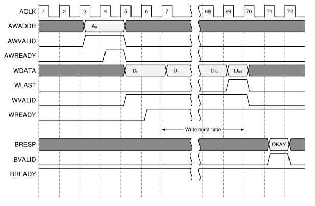
Write burst time¶ |
Read |
The read burst time is measured for a given burst using the following:
|
The following figure represents the read burst time measurement: 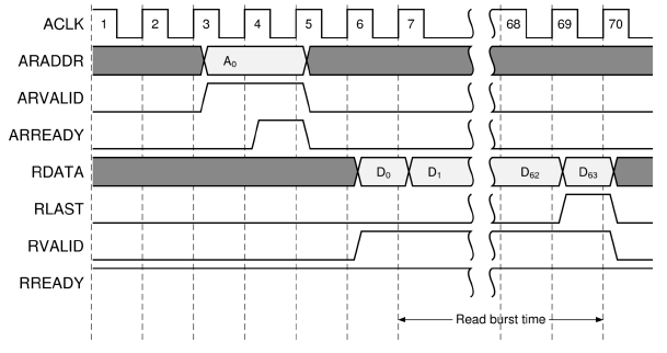
Read burst time¶ |
Bandwidth
The average write/read bandwidth is computed as write/read burst size divided by average write/read burst time. The measured average bandwidth can be checked against thresholds when enabled.
Important
The bandwidth checks are disabled by default when the host memory is targeted.
Latency
The following sections describes the start and end point for latency measurement. The Memory test case reports minimum, average and maximum burst latency. The measured average latency can be checked against thresholds when enabled.
Latency |
Description |
Illustration |
|---|---|---|
Write |
The write burst latency is measured for a given burst using the following:
|
The following figure represents the write latency measurement: 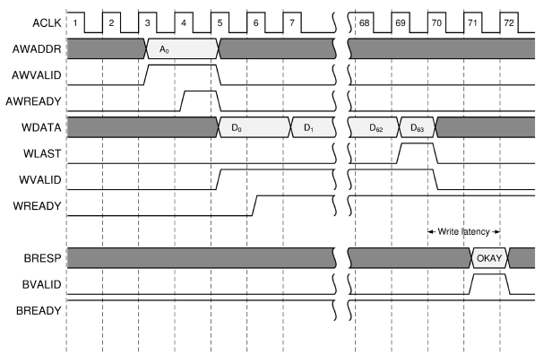
Write burst latency¶ |
Read |
The read burst latency is measured for a given burst using the following:
|
The following figure represents the read latency measurement. 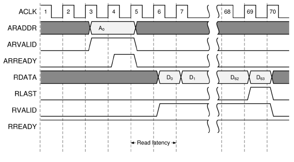
Read burst latency¶ |
Bandwidth and latency check conditions
The average read/write bandwidth and latency are checked against thresholds only when the following parameters are set to their nominal values:
duration is greater than 20 seconds.
wr_rate, rd_rate, wr_burst_size, rd_burst_size, wr_outstanding and rd_outstanding equal nominal values specified in Platform definition.
wr_block_size, rd_block_size, wr_start_addr and rd_start_addr are set such as the full memory size is check.
These nominal values are used by default. If any of them is overwritten, the check of the bandwidth and latency are disabled and a warning (MEM_050) is reported.
This can be overruled by setting check_bw or check_latency if it is still required.
Memory CU types
Different Alveo™ cards support various memory types of different sizes (for example, multiple 16 GB of DDR, 8 GB of HBM, 2 GB of PL-DDR, and/or 4 GB of PS-DDR) which are automatically detected by xbtest during the verify test case. Each of these memories is tested with either of these different types of memory CU:
Single-channel: One or more CU with 1 channel (1 AXI interface). Each CU targets a different memory entirely. All Memory test cases for each single-channel memory CU run in parallel. For example, DDR, PL_DDR or HOST are single-channel memory types.
multi-channel : Only one CU with up to 32 channels targeting different areas of the same memory. All Memory test cases for each channel of the multi-channel memory CU run in parallel. For example, HBM, PS_DDR are multi-channel memory types.
Note
For example, as the HBM stack can be split into pseudo channels (PCs) (see AXI High Bandwidth Controller LogiCORE IP Product Guide (PG276)), a multi-channel memory CU is used. Each channel of the memory CU can be connected either one or more PCs.
For each memory types, the size of AXI W/RDATA buses can be different. The maximum data size is typically used (512 bits) but it can be lower for example for PS_DDR memory type (128 bits).
Note
Different Alveo™ cards might have different memory types.
To identify the names of available memory types on the card selected with card BDF <BDF>,
use the following command (see Command line options):
$ xbtest -d <BDF> -g memory
More information on the configuration is also available in xbtest.log, with message ID ITF_058 for each memory type and message ID ITF_100 for each CU.
Memory CU type |
Description |
Illustration |
|---|---|---|
32-channel HBM |
One 32-channel memory CU, with each channel targets a different HBM PC (different memory tags). |
 32-channel HBM memory CU type¶ |
16-channel HBM |
One 16-channel memory CU, with each channel targeting a different series of two HBM PCs (different memory tags). |
 16-channel HBM memory CU type¶ |
DDR |
Four single-channel memory CUs, with each CU targeting a different DDR. |
 DDR memory CU type¶ |
PS_DDR |
One 4-channel memory CU, with each channel targeting a different area of the same memory (same memory tag). |
 PS_DDR memory CU type¶ |
Write and read ranges/blocks
Data is transferred from/to the memory via multiple AXI bursts, which address linearly the entire range of the memory. By default, the entire range of the memory is tested. When the memory CU is:
Single-channel: The range is simply the size of the memory.
multi-channel: The range is based on the quantity of memories connected to each channel of the memory CU. For example, with:
32-channel HBM: Each channel of the memory CU has a range of 256 MB (size of one HBM Pseudo Channel).
16-channel HBM: Each channel of the memory CU has a range of 512 MB (size of two HBM Pseudo Channel).
Throughout the documentation, the terminology of block is also used to refer to the range under test.
The wr_block_size and rd_block_size can be overwritten.
A block of data is fully:
Written to the memory, when the last burst of data is acknowledged (
BVALID) to the memory CU.Read from the memory, when the last data (
RLAST) of the last burst is received by the memory CU.
For more information about AXI protocol, refer to Vivado Design Suite: AXI reference guide (UG1037).
Note
When a block of data is fully read/written, the memory CU repeats the transfer of data during the entire duration, but the memory range is always entirely transferred. The duration of the test is automatically increased accordingly, meaning that the reading/writing of a block is never interrupted.
Test modes
The memory CUs can be configured to write and/or read data to/from the targeted memory in four different modes set with parameter mode.
Test mode |
Description |
Illustration |
|---|---|---|
|
The memory range (block) is fully written over and over during the entire duration of the test. |
The following figure represents the blocks transferred during an 
|
|
The memory range (block) is fully read over and over during the entire duration of the test. A single preliminary write (with known PRBS31 data) of the memory is performed prior starting the reading. |
The following figure represents the blocks transferred during an 
|
|
The first half of the memory range is fully written and the second half of the memory range is read simultaneously.
A single preliminary write (with known PRBS31 data) of the second half of the memory is performed prior starting the reading.
The following figure represents the blocks transferred during a |
The following figure represents the blocks transferred during a 
|
|
The full range of the memory is written, then fully read, over and over during the entire duration of the test. |
The following figure represents the blocks transferred during an 
|
AXI bursts
The memory CU communicates with the memory via one or more AXI interfaces (channels). The size of the AXI burst is typically 4 kB. For more information about AXI protocol, refer to Vivado Design Suite: AXI reference guide (UG1037).
AXI data size (in bits) |
AXI beat quantity |
AXI burst size (in kB) |
|---|---|---|
512 |
64 |
4 |
256 |
128 |
4 |
128 |
128 |
2 |
The wr_burst_size and rd_burst_size can be overwritten.
Maximum number of outstanding transactions
The memory CUs can be configured to limit the number of outstanding write and/or read transaction to/from the targeted memory.
The maximum number of outstanding transaction impact the Bandwidth and Latency measurements.
The wr_outstanding and rd_outstanding can be overwritten.
Maximum number of outstanding writes
An outstanding write transaction is defined as:
Start point: when
AWVALIDandAWREADYare asserted.End point: when
BVALIDandBREADYare asserted.
Maximum number of outstanding writes |
Illustration |
|---|---|
1 |
The following figure represents the AXI bursts when the number of outstanding writes is limited to 1.  Outstanding writes limited to 1.¶ |
2 |
The following figure represents the AXI bursts when the maximum number of outstanding writes is set to 2.  Outstanding writes limited to 2¶ |
0 (not limited) |
The following figure represents the AXI bursts when the number of outstanding writes is not limited.  Outstanding writes not limited¶ |
Maximum number of outstanding reads
An outstanding read transaction is defined as:
Start point: when
ARVALIDandARREADYare asserted.End point: when
RVALID,RLASTandRREADYare asserted.
Maximum number of outstanding reads |
Illustration |
|---|---|
1 |
The following figure represents the AXI bursts when the number of outstanding reads is limited to 1.  Outstanding reads limited to 1.¶ |
2 |
The following figure represents the AXI bursts when the maximum number of outstanding reads is set to 2.  Outstanding reads limited to 2.¶ |
0 (not limited) |
The following figure represents the AXI bursts when the number of outstanding reads is not limited.  Outstanding reads not limited¶ |
AXI ID threads
The memory CU can be configured to support multiple AXI ID threads (see AXI reference guide (UG1037)).
The maximum number of AXI ID threads supported by the memory CU is reported by the host application in messages ITF_058.
By default, the memory CU will transfer data to/from the memory using the maximum number of ID thread. When the parameter single_axi_thread is set, the memory CU will only use a constant ID for all AXI transactions.
When multiple AXI ID threads are enabled, the memory CU will generate each consecutive AXI burst request with a different, rotating AXI ID. For example, if the number of AXI ID threads is 4, then the AXI ID of the consecutive requests will be: 0, 1, 2, 3, 0, 1, 2, 3, 0, etc.
Quality of Service (QoS) - Rate control
Depending on the memory (or DMA and Slave bridge) controller built time settings, you may notice that write and read bandwidths are not even (or balanced) during simultaneous_wr_rd test. Although it may not change the total bandwidth available, you may want to change the way write and read bandwidths are shared. This can be achieved by using rate control, wr/rd_rate (see test_sequence).
By controlling individually wr_rate and rd_rate, you’ll be able to slow down (or accelerate) the quantity of write or read requests created by the memory CU. This rate control is still subject to Maximum number of outstanding transactions. So, you may need to increase or simply disable them to achieve the expected results.
All default settings are defined in Platform definition. Changing any default settings automatically disables the check of the results against thresholds (when applicable), see Bandwidth and latency check conditions. If it’s not the desired behaviour, you’ll need to enable manually these checks in your test JSON file by using check_bw or check_latency.
Memory Test JSON Members
Target memories on the card
Following is an example of Memory test cases targeting all memories of type DDR and HBM available on the card. Note that all memories are tested in parallel.
"memory" : {
  "DDR": {
    "global_config": {
      "test_sequence": [
        { "duration": 30, "mode": "simultaneous_wr_rd" },
        { "duration": 30, "mode": "only_wr" },
        { "duration": 30, "mode": "only_rd" },
        { "duration": 30, "mode": "alternate_wr_rd" }
      ]
    }
  },
  "HBM": {
    "global_config": {
      "test_sequence": [
        { "duration": 30, "mode": "simultaneous_wr_rd" },
        { "duration": 30, "mode": "only_wr" },
        { "duration": 30, "mode": "only_rd" },
        { "duration": 30, "mode": "alternate_wr_rd" }
      ]
    }
  }
}
Target memory on the host
Following is an example of Memory test case targeting all memories of type HOST:
"memory" : {
  "HOST": {
    "global_config": {
      "test_sequence": [
        { "duration": 30, "mode": "simultaneous_wr_rd" },
        { "duration": 30, "mode": "only_wr" },
        { "duration": 30, "mode": "only_rd" },
        { "duration": 30, "mode": "alternate_wr_rd" }
      ]
    }
  }
}
Single-channel override
For single-channel memory types, some test JSON members can be overwritten for each tag targeted by the memory CUs using the test JSON member memory_tag_config.
The following example shows how to run a Memory test case only for one (identified by memory tag DDR[1]) of the memories of the single-channel memory type named DDR.
"memory" : {
  "DDR": {
    "global_config": {
      "test_sequence": [
        { "duration": 30, "mode": "simultaneous_wr_rd" }
      ],
      "disable_memory": true
    },
    "memory_tag_config": {
      "DDR[1]": {
        "disable_memory": false
      }
    }
  }
}
Multi-channel override
For multi-channel memory types, some test JSON members can be overwritten for each channel of the memory CU using the test JSON member memory_channel_config.
The following example shows how to run a Memory test case only for one (channel 12) channel of the multi-channel memory type named HBM.
"memory" : {
  "HBM": {
    "global_config": {
      "test_sequence": [
        { "duration": 30, "mode": "simultaneous_wr_rd" }
      ],
      "disable_memory": true
    },
    "memory_channel_config": {
      "12": {
        "disable_memory": false
      }
    }
  }
}
Definition
In the Memory test case, valid test JSON members depend on the configuration of the memory CUs (see Memory CU types), which are automatically detected by the Application software during the verify test case. The following table shows all members available for this test case. More details are provided for each member in the subsequent sections:
Member |
Mandatory / optional |
Description |
|---|---|---|
Mandatory |
Describes the sequence of tests to perform. |
|
Optional |
Enable the check of the bandwidths. This check is by default for memories available:
|
|
Optional |
Overwrite high threshold of write/read bandwidth (MB/s). |
|
Optional |
Overwrite low threshold of the write/read bandwidth (MB/s). |
|
Optional |
Enable the check of the latencies. This check is by default for memories available:
|
|
Optional |
Overwrite high threshold of write/read latency (ns). |
|
Optional |
Overwrite low threshold of the write/read latency (ns). |
|
Optional |
Disable write of valid PRBS31 data in the memory
before any |
|
Optional |
Disable memory test case. |
|
Optional |
Disable usage of multiple AXI ID threads. |
test_sequence
Mandatory. Describes the sequence of tests to perform. Tests are performed serially, and a failure in one test does not stop the sequence (the next test will be launched). There is no limitation to the length of the test sequence.
This field contains a list of tests, each test being defined by an object of key–value parameters pairs: [ {}, {}, {} ].
The following table defines the parameters supported in the Memory test sequence:
Member |
Mandatory / optional |
Description |
|---|---|---|
|
Mandatory |
The duration of the test in seconds; Range [1, 232-1]. |
|
Mandatory |
Test mode; Possible value: |
|
Optional |
Write/read rate in percent; Overwrites nominal rate specified in platform definition file (see Platform definition). Range: [1, 100]; |
|
Optional |
Write/read burst size. Overwrites nominal burst size specified in platform definition file (see Platform definition, or defaults to its maximum when not specified). Range:
|
|
Optional |
Maximum number of outstanding write/read transaction; Overwrites nominal value specified in platform definition file (see Platform definition). Range: [0, 255]; A value of 0 means the number of outstanding writes/reads is not limited. |
|
Optional |
Optional write/read block size. Default value is such as the full range of memory is tested. Range depends on mode, memory size, wr_start_addr and rd_start_addr. |
|
Optional |
Optional write/read start address offset. Default value is such as the full range of memory is tested. Range depends on mode, memory size, wr_block_size and rd_block_size. |
For example:
Single test:
Multiple tests:
The write and read memory areas, defined by wr_start_addr, rd_start_addr, wr_block_size and rd_block_size:
Must be the same when
modeisalternate_wr_rd, such as:
Valid:
"test_sequence": [ { "duration": 60, "mode": "alternate_wr_rd", "wr_start_addr": 0, "wr_block_size": 256, "rd_start_addr": 0, "rd_block_size": 256 } ]Invalid:
"test_sequence": [ { "duration": 60, "mode": "alternate_wr_rd", "wr_start_addr": 0, "wr_block_size": 256, "rd_start_addr": 128, "rd_block_size": 256 } ]Cannot overlap when
modeissimultaneous_wr_rd, such as:
Valid:
"test_sequence": [ { "duration": 60, "mode": "simultaneous_wr_rd", "wr_start_addr": 0, "wr_block_size": 256, "rd_start_addr": 512, "rd_block_size": 256 } ]Invalid:
"test_sequence": [ { "duration": 60, "mode": "simultaneous_wr_rd", "wr_start_addr": 0, "wr_block_size": 256, "rd_start_addr": 128, "rd_block_size": 256 } ]
Override test_sequence
The test_sequence can be overwritten for each channel of the multi-channel memory CU or for each memory tag targeted by the single-channel memory CUs.
The number of tests in all test_sequence parameters specified for a memory type must be the same.
The duration of a test must be the same in all test_sequence.
The following example shows how to run a Memory test case of the multi-channel memory type named HBM where mode is set to:
only_rd, thenonly_wrfor channel1.
only_wr, thenonly_rdfor all other channels.
"memory" : {
  "HBM": {
    "global_config": {
      "test_sequence": [
        { "duration": 15, "mode": "only_wr" },
        { "duration": 25, "mode": "only_rd" }
      ]
    },
    "memory_channel_config": {
      "1": {
        "test_sequence": [
          { "duration": 15, "mode": "only_rd" },
          { "duration": 25, "mode": "only_wr" }
        ]
      }
    }
  }
}
The following example shows how to run a Memory test case of the multi-channel memory type named HBM where mode is set to:
only_wronly for channelDDR[2].
only_wr, thenonly_rdfor all other DDR memory banks.
"memory" : {
  "DDR": {
    "global_config": {
      "test_sequence": [
        { "duration": 1,  "mode": "only_wr" },
        { "duration": 15, "mode": "only_rd" }
      ]
    },
    "memory_tag_config": {
      "DDR[2]": {
        "test_sequence": [
          { "duration": 1,  "mode": "only_wr" },
          { "duration": 15, "mode": "only_wr" }
        ]
      }
    }
  }
}
check_bw
Optional;
Type : boolean;
Possible values: true or false;
Default : for memories available:
On the card:
true.On the host:
false.
By setting this member to false, no average bandwidth measurement will be compared against defined thresholds.
When set to true, average bandwidth measurements will be checked even if the test parameters are not nominal (see Bandwidth and latency check conditions).
Default bandwidth limits are defined in Platform definition and are displayed at the beginning of the tests.
The bandwidth limits can be overwritten using the following parameters:
hi_thresh_alt_wr_bw, hi_thresh_alt_rd_bw, hi_thresh_only_wr_bw, hi_thresh_only_rd_bw, hi_thresh_simul_wr_bw, hi_thresh_simul_rd_bw
Optional; Type : integer; Range : [1, 232-1]; Default: specified in the Platform definition.
Overwrite high threshold of the average write/read bandwidth (MB/s) specified in Platform definition.
After all bandwidth measurements made during the test duration are complete, if the measured average bandwidth is greater than this threshold, the test fails.
The following table gives the write and read bandwidth high thresholds based on mode:
Test mode |
Write BW threshold |
Read BW threshold |
|---|---|---|
|
||
|
n/a |
|
|
n/a |
|
|
lo_thresh_alt_wr_bw, lo_thresh_alt_rd_bw, lo_thresh_only_wr_bw, lo_thresh_only_rd_bw, lo_thresh_simul_wr_bw, lo_thresh_simul_rd_bw
Optional; Type : integer; Range : [1, 232-1]; Default: specified in the Platform definition.
Overwrite low threshold of the average write/read bandwidth (MB/s) specified in Platform definition.
After all bandwidth measurements made during the test duration are complete, if the measured average bandwidth is lower than this threshold, the test fails.
Low threshold must be lower than high threshold. The following table gives the write and read bandwidth low thresholds based on mode:
Test mode |
Write BW threshold |
Read BW threshold |
|---|---|---|
|
||
|
n/a |
|
|
n/a |
|
|
check_latency
Optional;
Type : boolean;
Possible values: true or false;
Default : for memories available:
On the card:
true.On the host:
false.
By setting this member to false, no latency measurement (read or write) is checked against pass/failed criteria.
When set to true, average latency measurements will be checked even if the test parameters are not nominal (see Bandwidth and latency check conditions).
Default latency limits are defined in Platform definition and are displayed at the beginning of the tests.
The latency limits can be overwritten using the following parameters:
hi_thresh_alt_wr_lat, hi_thresh_alt_rd_lat, hi_thresh_only_wr_lat, hi_thresh_only_rd_lat, hi_thresh_simul_wr_lat, hi_thresh_simul_rd_lat
Optional; Type : integer; Range : [1, 232-1]; Default: specified in the Platform definition.
Overwrite high threshold of the average write/read latency (ns) specified in Platform definition.
After all latency measurements made during the test duration are complete, if the measured average latency is greater than this threshold, the test fails.
The following table gives the write and read latency high thresholds based on mode:
Test mode |
Write latency threshold |
Read latency threshold |
|---|---|---|
|
||
|
n/a |
|
|
n/a |
|
|
lo_thresh_alt_wr_lat, lo_thresh_alt_rd_lat, lo_thresh_only_wr_lat, lo_thresh_only_rd_lat, lo_thresh_simul_wr_lat, lo_thresh_simul_rd_lat
Optional; Type : integer; Range : [1, 232-1]; Default: specified in the Platform definition.
Overwrite low threshold of the average write/read latency (ns) specified in Platform definition.
After all latency measurements made during the test duration are complete, if the measured average latency is lower than this threshold, the test fails.
Low threshold must be lower than high threshold.
The following table gives the write and read latency high thresholds based on mode:
Test mode |
Write latency threshold |
Read latency threshold |
|---|---|---|
|
||
|
n/a |
|
|
n/a |
|
|
disable_prewrite
Optional;
Type : boolean;
Possible values: true or false;
Default : false.
When set to
false, xbtest loads a valid PRBS31 data sequence in the memory before anyonly_rdorsimultaneous_wr_rdtest.When set to
true, this is disabled. The presence of valid PRBS data in the memory can be managed manually within your test_sequence, defining at least oneonly_wrtest prior to the firstonly_rdorsimultaneous_wr_rdtest.
disable_memory
Optional;
Type : boolean;
Possible values: true or false;
Default : false.
By default, for all memory CUs, all channels are enabled and the associated memory is checked.
single_axi_thread
Optional;
Type : boolean;
Possible values: true or false;
Default : false.
By default, for all memory CUs, the maximum number of ID threads supported is used to transfer data from/to the memory.
When set to
true, the memory CU use the same constant ID (set to 0) for all AXI transactions.
This parameter is supported only if the memory type supports multiple AXI ID threads.
Output files
All memory measurements are stored in output CSV files which are generated in xbtest logging directory. The values are stored in CSV type format with one column for each information type.
Important
If the command line option -L is used while calling the Application software, no output file is generated.
In the Memory test case, different CSV files are used to store all Memory test case results:
Output file |
Description |
Naming convention |
|---|---|---|
Configuration and results for each test of the test_sequence. These files are named with |
Files are named with a prefix the following convention:
Where:
In addition, for multi-channel memory types, another prefix is used:
These files contain the combined results for all channels of the memory CU:
|
|
All intermediate bandwidth and latency results computed every second. These files are named with |
||
Contains the configuration and the results for each channels of the memory CU grouped to allow easier comparison of results between each channel. These files are generated for multi-channel memory types only. |
Files are named |
|
Contains the configuration and all power measurements. |
Files are named |
For example, depending on the memory type supported by xbtest for targeted deployment platform, the generated output CSV files are:
One single-channel memory type named DDR with 2 memory CU (one connected to
DDR[0]and the other one toDDR[1]):
memory_ddr[0]_detail.csv.
memory_ddr[0]_result.csv.
memory_ddr[1]_detail.csv.
memory_ddr[1]_result.csv.
memory_DDR_ddr[0]_power.csv.
memory_DDR_ddr[1]_power.csv.One multi-channel memory type named HBM with a 16-channel memory CU (channel 0 connected to
HBM[0:1], channel 1 toHBM[2:3], … and channel 15 toHBM[30:31]):
memory_hbm[0_1]_ch_0_detail.csv.
memory_hbm[0_1]_ch_0_result.csv.
memory_hbm[2_3]_ch_1_detail.csv.
memory_hbm[2_3]_ch_1_result.csv.…
memory_hbm[30_31]_ch_15_detail.csv.
memory_hbm[30_31]_ch_15_result.csv.
memory_HBM_combined_detail.csv.
memory_HBM_combined_result.csv.
memory_HBM_mc_summary.csv.
memory_HBM_power.csv.
Results CSV output files
For each test of the test_sequence, a new row containing the test configuration and results computed is present in this file. All columns present in the file are defined as:
Test: Index of current test within the test_sequence. Index of first test is 1.
duration (s): Duration of current test within the test_sequence.
test mode: mode of current test within the test_sequence.
data integrity: Overall data integrity result: set to
KOif data integrity error was detected, otherwise set toOK.average total write+read BW (MBps): Sum of average write BW (MBps) and average read BW (MBps).
write configuration: This group contains the following columns. These columns are set to
n/awhen mode isonly_rd.
write rate (%): Rate used for writing the memory.
write start address offset (MB): Starting address of the memory to be written.
write end address offset (MB): Ending address of the memory to be written.
write burst size (Bytes): Size of each bursts to be written in the memory.
write block size (MB): Size of the block to be written in the memory.
maximum number of outstanding writes: Limit of outstanding write transactions.
AXI write data size (Bytes): Size of an AXI beat in a burst.
number of write transfers per burst: Quantity of AXI beats per burst for write direction.
total number of write bursts per block: Quantity of bursts per block for write direction.
total number of write transfers per block: Quantity of AXI beats to write the memory based on write block size (MB) and AXI write data size (Bytes).
write results: This group contains the following columns. These columns are set to
n/awhen mode isonly_rd.
average write BW (MBps): Average write BW (MB/s).
average number of write bursts per second: Average quantity of bursts written in the memory every second.
minimum write burst time (ns): Minimum time needed for writing a burst.
average write burst time (ns): Average time needed for writing a burst.
maximum write burst time (ns): Maximum time needed for writing a burst.
minimum write burst latency (ns): Minimum latency for writing a burst.
average write burst latency (ns): Average latency for writing a burst.
maximum write burst latency (ns): Maximum latency for writing a burst.
read configuration: Same columns as write configuration group but for read direction. These columns are set to
n/awhen mode isonly_wr.read results: Same columns as write results group but for read direction. These columns are set to
n/awhen mode isonly_wr.
Note
When you Override test_sequence, then for multi-channel memory types in the output CSV file with prefix memory_<type>_combined (where <type> is the name of the memory type):
The configuration parameters are set to
OVR. The parameters used for each channel are available in their own output CSV file.The combined BW and latency measurements depend on which channels are writing and/or reading from/to the memory.
Detail CSV output files
This file contains all intermediate bandwidths computed every second, based on information retrieved from the memory CU. There is one line of result for every second of each test of the test_sequence. All columns present in the file are defined as:
Global time (s): Global elapsed time since the
Testsoftware execution started.Test: Index of current test within the test_sequence. Index of first test is 1.
test mode: mode of current test within the test_sequence.
Measurement ID: Measurement identifier. ID of first measurement is 0.
data integrity results: This group contains the following columns. These columns are set to
n/awhen mode isonly_wr.
live data integrity: Live data integrity result: set to
KOwhen data integrity error is detected, otherwise set toOK.data integrity: Overall data integrity result: set to
KOas soon as data integrity error is detected, otherwise set toOK.write+read BW: This group contains the following columns.
live total write+read BW (MBps): Sum of live write BW (MBps) and live read BW (MBps).
average total write+read BW (MBps): Sum of average write BW (MBps) and average read BW (MBps).
write results: This group contains the following groups. These columns are set to
n/awhen mode isonly_rd.
write BW: This group contains the following columns.
live write BW (MBps): Current live measurement of write BW measurement.
average write BW (MBps): Current average value of write BW measurements.
number of write bursts: This group contains the following columns.
live number of write bursts per second: Current live number of write bursts per second performed by the memory CU.
average number of write bursts per second: Current average number of write bursts per second performed by the memory CU.
write burst time: This group contains the following columns.
live minimum write burst time (ns): Current live measurement of minimum write burst time.
minimum write burst time (ns): Current average value of minimum write burst time measurements.
live average write burst time (ns): Current live measurement of average write burst time.
average write burst time (ns): Current average value of average write burst time measurements.
live maximum write burst time (ns): Current live measurement of maximum write burst time.
maximum write burst time (ns): Current average value of maximum write burst time measurements.
write burst latency: This group contains the following columns.
live minimum write burst latency (ns): Current live measurement of minimum write burst latency.
minimum write burst latency (ns): Current average value of minimum write burst latency measurements.
live average write burst latency (ns): Current live measurement of average write burst latency.
average write burst latency (ns): Current average value of average write burst latency measurements.
live maximum write burst latency (ns): Current live measurement of maximum write burst latency.
maximum write burst latency (ns): Current average value of maximum write burst latency measurements.
read results: Same columns as write results group but for read direction. These columns are set to
n/awhen mode isonly_wr.Timestamp: Timestamp read from memory CU. Counter incrementing by 1 every second.
Note
The live values are for internal use only of the Application software.
Note
When you Override test_sequence, then for multi-channel memory types in the output CSV file with prefix memory_<type>_combined (where <type> is the name of the memory type):
The configuration parameters are set to
OVR. The parameters used for each channel are available in their own output CSV file.The combined BW and latency measurements depend on which channels are writing and/or reading from/to the memory.
Multi-channel Summary CSV output files
For each test of the test_sequence, a new row containing the test configuration and results computed is present in this file. All columns present in the file are defined as:
Test: Index of current test within the test_sequence. Index of first test is 1.
duration (s): Duration of current test within the test_sequence.
test mode: mode of current test within the test_sequence.
write configuration: This group contains the following columns. These columns are set to
n/awhen mode isonly_rd.
write rate (%): Rate used for writing the memory.
write start address offset (MB): Starting address of the memory to be written.
write burst size (Bytes): Size of each bursts to be written in the memory.
write block size (MB): Size of the block to be written in the memory.
maximum number of outstanding writes: Limit of outstanding write transactions.
read configuration: Same columns as write configuration group but for read direction. These columns are set to
n/awhen mode isonly_wr.Combined results: This group contains the following columns. These columns for write and for read results are set to
n/awhen mode isonly_rdandonly_wrrespectively.
Combined average write BW (MBps): Average write BW (MB/s).
Combined average read BW (MBps): Average read BW (MB/s).
Combined average write burst latency (ns): Average latency for writing a burst.
Combined average read burst latency (ns): Average latency for reading a burst.
Combined average write burst time (ns): Average time needed for writing a burst.
Combined average read burst time (ns): Average time needed for reading a burst.
Combined data integrity: Overall data integrity result: set to
KOas soon as data integrity error is detected, otherwise set toOK.Combined average total write+read BW (MBps): Sum of average write BW (MBps) and average read BW (MBps).
Then, one column is present per channel <i>, for each of the following groups:
Ch
<i>average write BW (MBps): Average write BW (MB/s)Ch
<i>average read BW (MBps): Average read BW (MB/s).Ch
<i>average write burst latency (ns): Average latency for writing a burst.Ch
<i>average read burst latency (ns): Average latency for reading a burst.Ch
<i>average write burst time (ns): Average time needed for writing a burst.Ch
<i>average read burst time (ns): Average time needed for reading a burst.
Note
When you Override test_sequence, then in this output CSV file:
The configuration parameters are set to
OVR. The parameters used for each channel are available in their own output CSV file.The combined BW and latency measurements depend on which channels are writing and/or reading from/to the memory.
Power CSV output files
In this file, the test configuration and all power measurements are stored. A new line is written in this file every time the memory CU status are available. At a minimum, the following values are recorded:
Global time (s): Global elapsed time since the
Testsoftware execution started.Test: Index of current test within the test_sequence. Index of first test is 1.
test mode: Mode of current test within the test_sequence.
Measurement ID: Measurement identifier. ID of first measurement is 0.
write rate (%): Rate used for writing the memory.
read rate (%): Rate used for reading the memory.
Measurement valid: Set to
OKif theTestsoftware was able to successfully gets power and temperature measurements via the Xilinx® Runtime (XRT) native library C++ device APIs, otherwise set toKO.Mechanical measurements: Group of one or more columns recording measurements for each mechanical sensor source monitored by xbtest.
Thermal measurements: Group of one or more columns recording measurements for each thermal sensor source monitored by xbtest.
Electrical measurements: Group of one or more columns recording detailed measurements for each electrical sensor source monitored by xbtest.
See Sensor source definition for more information on the sensor sources monitored by xbtest.