Creating Custom IP and Device Drivers for Linux
In this chapter, you will create an intellectual property (IP) using the Create and Package New IP wizard. You will also design a system to include the new IP created for the Xilinx® Zynq®-7000 SoC device.
For the IP, you will develop a Linux-based device driver as a module that can be dynamically loaded onto the running kernel.
You will also develop Linux-based application software for the system to execute on the Zynq SoC ZC702 board.
Important
You will need to rebuild the Linux kernel: a Linux host machine to run PetaLinux is required.
Example 11: Creating Peripheral IP: Creating Peripheral IP
Example 12: Device Driver Development: Device Driver Development
example-13-loading-the-module-into-a-kernel-and-application-execution: Loading the Module into a Kernel and Executing the Application
Creating Peripheral IP
In this section, you will create an AXI4-Lite compliant slave peripheral IP framework using the Create and Package New IP wizard. You will also add functionality and port assignments to the peripheral IP framework.
The peripheral IP you will create is an AXI4-Lite compliant slave IP. It includes a 28-bit counter. The four most significant bits of the counter drive the four output ports of the peripheral IP. The block diagram is shown in the following figure.
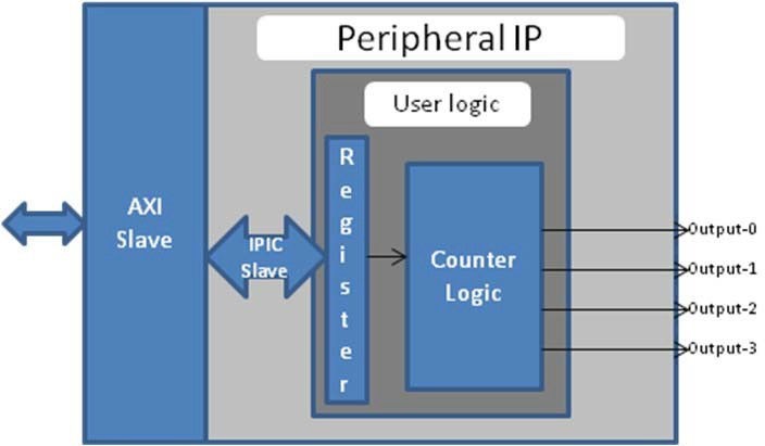
Custom IP Structure
The block diagram includes the following configuration register:
Register Name |
Control Register |
|---|---|
Relative Address |
0x0000_0000 |
Width |
1-bit |
Access Type |
Read/Write |
Description |
Start/Stop the Counter |
Field Name |
Bits |
Type |
Reset Value |
Description |
|---|---|---|---|---|
Control |
Bit 0 |
R/W |
0x0 |
1 : Start Counter 2 : Stop Counter |
Example 11: Creating Peripheral IP
Creating Peripheral IP
In this section, you will create an AXI4-Lite compliant slave peripheral IP.
Create a new project as described in Creating a New Embedded Project with Zynq SoC :ref:`example-1-creating-a-new-embedded-project-with-zynq-soc.
With the Vivado design open, select Tools → Create and Package New IP. Click Next to continue.
Select Create a new AXI4 peripheral and then click Next.
Fill in the peripheral details as follows:
Screen
System Property
Setting or Comment to Use
Peripheral Details
Name
Blink
Version
1.0
Display name
Blink_v1.0
Description
My new AXI IP
IP location
C:/designs/ip_repro
Overwrite
existing unchecked
Click Next.
In the Add Interfaces page, accept the default settings and click Next.
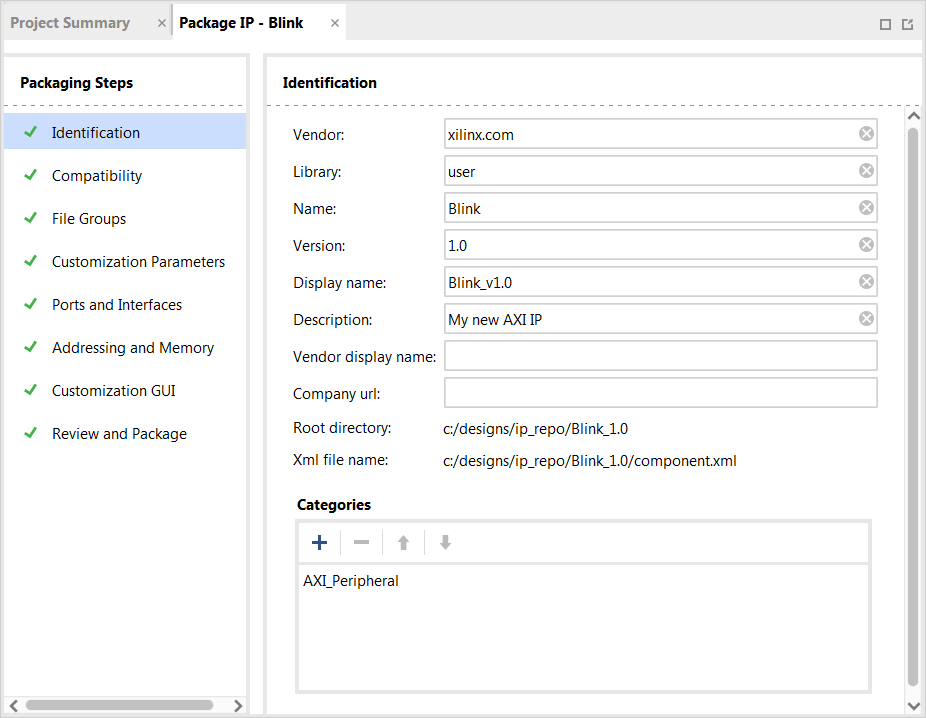
In the Create Peripheral page, select Edit IP and then click Finish. Upon completion of the new IP generation process, the Package IP window opens (see the following figure).
In the Hierarchy view of the Sources window, right-click blink_v1_0 under the Design Sources folder and select Open File. You need to add Verilog code that creates output ports to map to the external LEDs on the ZC702 board. Navigate to the line
//Users to add ports hereand addoutput wire \[3:0\] ledsbelow this line, as shown in the following example://Users to add ports here output wire [3:0] leds, //User ports ends
Find the instantiation to the AXI bus interface and add
.leds(leds), as shown in the following example, to map the port connections:.S_AXI_RREADY(s00_axi_rready), .leds(leds) );
Save and close blink_v1_0.v.
Under Sources → Hierarchy → Design Sources→ blink_v1_0, right-click blink_v1_0_S00_AXI_inst - blink_v1_0_S00_AXI and select Open File.
Next, you will need to add Verilog code that creates output ports to map to the external LEDs on the ZC702 board and also create the logic code to blink the LEDs when register 0 is written to.
Navigate to the line
//Users to add ports hereand addoutput wire \[3:0\] ledsbelow this line, as shown in the example below://Users to add ports here output wire [3:0] leds, //User ports ends
Find the AXI4-Lite signals section:
// AXI4LITE signals
  reg [C_S_AXI_ADDR_WIDTH-1 : 0] axi_awaddr;
  reg axi_awready;
  reg axi_wready;
  reg [1 : 0] axi_bresp;
  reg axi_bvalid;
  reg [C_S_AXI_ADDR_WIDTH-1 : 0] axi_araddr;
  reg axi_arready;
  reg [C_S_AXI_DATA_WIDTH-1 : 0] axi_rdata;
  reg [1 : 0] axi_rresp;
  reg axi_rvalid;
After this section, add a custom register, which you will use as a counter. Add the following code:
// add 28-bit register to use as counter
reg [27:0] count;
Find the I/O connections assignments section:
// I/O Connections assignments
  assign S_AXI_AWREADY = axi_awready;
  assign S_AXI_WREADY = axi_wready;
  assign S_AXI_BRESP = axi_bresp;
  assign S_AXI_BVALID = axi_bvalid;
  assign S_AXI_ARREADY = axi_arready;
  assign S_AXI_RDATA = axi_rdata;
  assign S_AXI_RRESP = axi_rresp;
  assign S_AXI_RVALID = axi_rvalid;
Add the following code at the bottom:
// assign MSB of count to LEDs
  assign leds = count[27:24];
Toward the bottom of the file, find the section that states
Add user logic here. Add the following code, which will increment the count while the slv_reg0 is set to 0x1. If the register is not set, the counter will not increment.// Add user logic here // on positive edge of input clock always @( posedge S_AXI_ACLK ) begin //if reset is set, set count = 0x0 if ( S_AXI_ARESETN == 1'b0 ) begin count <= 28'b0; end else begin //when slv_reg_0 is set to 0x1, increment count if (slv_reg0 == 2'h01) begin count <= count+1; end else begin count <= count; end end end // User logic ends
Save and close blink_v1_0_S00_AXI.v.
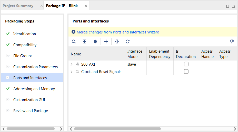
Open the Package IP - blink page. Under Packaging Steps, select Ports and Interfaces.
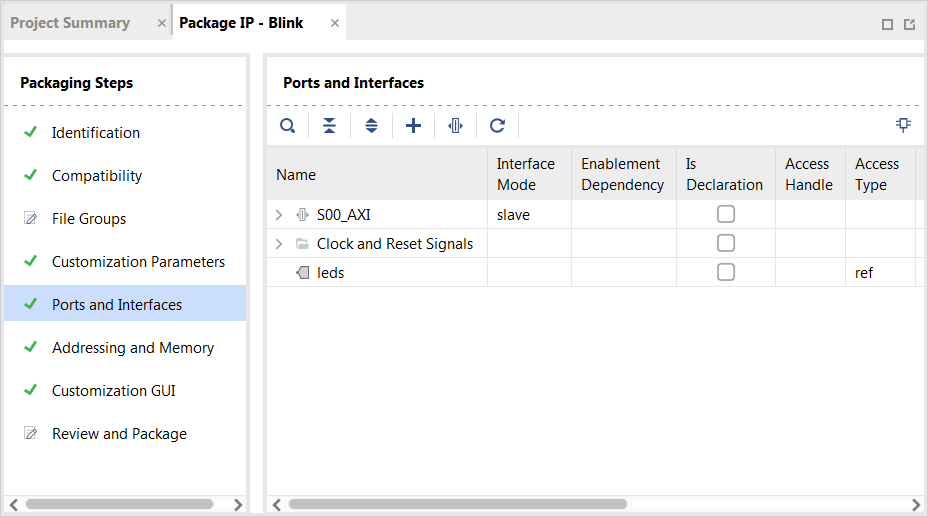
Click the Merge Changes from Ports and Interfaces Wizard link.
Make sure that the window is updated and includes the LEDs output ports.
Under Packaging Steps, select Review and Package. At the bottom of the Review and Package page, click Re-Package IP.
The view that opens states that packaging is complete and asks if you would like to close the project.
Click Yes.
Note
The custom core creation process that you have worked through is very simple with the example Verilog included in the IP creation process. For more information, refer to the GitHub Zynq Cookbook: How to Run BFM Simulation web page.
Integrating Peripheral IP with PS GP Master Port
You will now create a system for the ZC702 board by instantiating the peripheral IP as a slave in the Zynq SoC programmable logic (PL) section. You will then connect it with the processor through the processing system (PS) general purpose (GP) master port. The block diagram for the system is shown in the following figure.
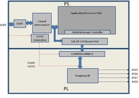
This system covers the following connections:
Peripheral IP connected to PS general purpose master port 0 (M_AXI_GP0). This connection is used by the PS CPU to configure peripheral IP register configurations.
Four output ports for peripheral IP connected to DS15, DS16, DS17, and DS18 on-board LEDs.
In this system, when you run application code, a message appears on the serial terminal and asks you to choose the option to make the LEDs start or stop blinking.
When you select the start option on the serial terminal, all four LEDs start blinking.
When you select the stop option, all four LEDs stop blinking and retain the previous state.
Connecting an AXI4-Lite Compliant Custom Slave IP
In this section, you will connect the AXI4-Lite compliant custom slave peripheral IP that you created in Creating Peripheral IP.
Open the Vivado project you previously created in Example 1: Creating a New Embedded Project with Zynq SoC.
Add the custom IP to the existing design. Right-click the Diagram view and select Add IP.
Type “blink” into the search view. Blink_v1.0 appears. Double-click the IP to add it to the design.
Click Run Connection Automation to make automatic port connections.
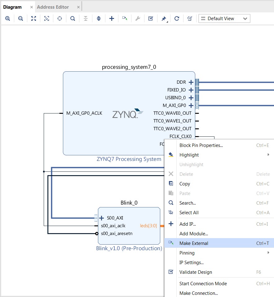
With the All Automation box checked by default, click OK to make the connections. Your new IP is automatically connected, but the leds output port is disconnected.
Right-click the leds port and select Make External.
In the Flow Navigator view, navigate to RTL Analysis and select Open Elaborated Design.
Click OK.
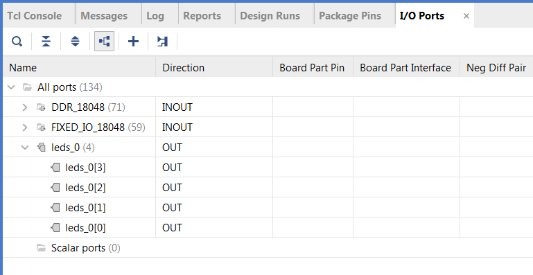
After the elaborated design opens, click the I/O Ports window and expand All ports → led_0.
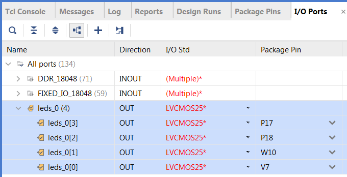
Edit the leds port settings as follows:
Port Name
I/O Std
Package Pin
Leds[3]
LVCMOS25
P17
Leds[2]
LVCMOS25
P18
Leds[1]
LVCMOS25
W10
Leds[0]
LVCMOS25
V7
The following figure shows the completed leds port settings in the I/O Ports window.
Select Generate Bitstream.
The Save Project view opens. Ensure that the check box is selected and then click Save.
If a message appears stating that synthesis is Out-of-date, click Yes.
After the bitstream generation completes, export the hardware and launch the Vitis unified software platform.
Note
Make sure to select Include bitstream instead of Pre-synthesis on the Output page of the Export Hardware Platform wizard.
Linux-Based Device Driver Development
Modules in Linux are pieces of code that can be loaded and unloaded into the kernel on demand. A piece of code that you add in this way is called a loadable kernel module (LKM). These modules extend the functionality of the kernel without the need to reboot the system. Without modules, you would need to build monolithic kernels and add new functionality directly into the kernel image. Besides having larger kernels, this has the disadvantage of requiring you to rebuild and reboot the kernel every time you want new functionality. > LKMs typically are one of the following things:
Device drivers: A device driver is designed for a specific piece of hardware. The kernel uses it to communicate with that piece of hardware without having to know any details of how the hardware works.
File system drivers: A file system driver interprets the contents of a file system as files and directories.
System calls: User space programs use system calls to get services from the kernel.
On Linux, each piece of hardware is represented by a file named as a device file, which provides the means to communicate with the hardware. Most hardware devices are used for output as well as input, so device files provide input/output control (ioctl) to send and receive data to and from hardware. Each device can have its own ioctl commands, which can be of the following types:
read ioctl: These commands send information from a process to the kernel.
write ioctl: These commands return information to a process.
Both read and write ioctl.
Neither read nor write ioctl.
For more details about LKM, refer to the Linux Kernel Module Programming Guide.
In this section you are going to develop a peripheral IP device driver as an LKM, which is dynamically loadable onto the running kernel. You must build the peripheral IP LKM as part of the same kernel build process that generates the base kernel image.
Note
If you do not want to compile the device driver, you can skip the example in this section and jump to example-13-loading-the-module-into-a-kernel-and-application-execution. In that section, you can use the kernel image, which contains blink.ko (image.ub in the shared ZIP files). See Design Files for this Tutorial.
For kernel compilation and device driver development, you must use the Linux workstation. Before you start developing the device driver, the following steps are required:
Set the toolchain path in your Linux workstation.
Download the kernel source code and compile it. For downloading and compilation, refer to the steps mentioned in the Xilinx Zynq Linux Wiki Page.
Example 12: Device Driver Development
You will use a Linux workstation for this example project. The device driver software is provided in the LKM folder of the ZIP file that accompanies this guide.
Under the PetaLinux project directory, use the command below to create your module:
petalinux-create -t modules \--name mymodule \--enable
PetaLinux creates the module in the <plnx-project>/project-spec/meta-user/ recipes-modules/ directory.
For this exercise, create the “blink” module:
petalinux-create -t modules \--name blink \--enable
The default driver creation includes a Makefile, C-file, and README files. In this exercise, PetaLinux creates
blink.c, a Makefile, and README files. It also contains the bit bake recipeblink.bb.Change the C-file (driver file) and the Makefile as per your driver.
Take the LKM folder (reference files) and copy blink.c and blink.h into this directory.
Open the blink.bb recipe and add a
blink.hentry inSRC_URI.Run the command
petalinux-build.After successful compilation the
.kofile is created in the following location:<petalinux-build_directory>/build/tmp/sysroots-components/zc702_zynq7/blink/lib/modules/5.4.0-xilinx-v2021.2/extra/blink.ko
You can install the driver using the
modprobecommand, which will be explained in further detail in the next section.
.._example-13-loading-the-module-into-a-kernel-and-application-execution:
Example 13: Loading a Module into a Kernel and Executing the Application
In this example, you will boot Linux onto the Zynq SoC Board and load the peripheral IP as an LKM onto it. You will develop the application for the system and execute it onto the hardware.
Loading the Module into Kernel Memory
The modprobe command makes an init_module system call to load the LKM into the kernel memory. The init_module system call invokes the LKM initialization routine immediately after it loads the LKM. As part of its initialization routine, insmod passes to the address of the subroutine to init_module.
In the peripheral IP device driver, you already set up init_module to call a kernel function that registers the subroutines. It calls the kernel’s register_chrdev subroutine, passing the major and minor number of the devices it intends to drive and the address of its own “open” routine among the arguments. The subroutine register_chrdev specifies in base kernel tables that when the kernel wants to open that particular device, it should call the open routine in your LKM.
Application Software
The main() function in the application software is the entry point for the execution. It opens the device file for the peripheral IP and then waits for the user selection on the serial terminal.
If you select the start option on the serial terminal, all four LEDs start blinking. If you select the stop option, all four LEDs stop blinking and retain the previous state.
Example Steps
Booting Linux on the Target Board
Boot Linux on the Zynq SoC ZC702 target board.
Loading Modules and Executing Applications
In this section, you will use the Vitis software platform installed on a Windows machine.
Open the Vitis software platform. You must run the Target Communication Frame (TCF) agent on the host machine.
In the XSCT Console view, type
connectto connect to the Xilinx Software Command-Line Tool (XSCT).In the Vitis software platform, select File → New → Application Project to open the New Application Project wizard.
Use the information in the table below to make your selections in the wizard screens.
Screen
System Property
Setting or Command to Use
Platform
Select a platform from repository
Click hw_platform [custom].
Application Project Details
Application project name
Enter linux_blinkled_app
Select target processor for the Application project
Select ps7_cortexa9 SMP.
Domain
Select a domain
Click linux_application_domain.
Application settings
If known, enter the sysroot, root FS, and kernel image paths. Otherwise, leave these options blank.
Templates
Available Templates
Linux Empty Application
Click Finish. The New Application Project wizard closes and the Vitis software platform creates the linux_blinkled_app project under the Explorer view.
In the Explorer view, expand the linux_blinkled_app project, right-click the src directory, and select Import. The Import Sources view opens.
Browse for the LKM_App folder and select the linux_blinkled_app.c and blink.h files.
Note
The application software file name for the system is
linux_blinkled_app.cand the header file name isblink.h. These files are available in the LKM folder of the ZIP file that accompanies this guide. See Design Files for this Tutorial.Add the linux_blinkled_app.c and blink.h files.
Click Finish.
Right-click on the linux_blinkled_app project and select Build Project to generate the
linux_blinkled_app.elffile in binary folders. Check the Console window for the status of this action.Connect the board.
Because you have a bitstream for the PL fabric, you must download the bitstream. Select Xilinx → Program FPGA. The Program FPGA view opens. It displays the bitstream exported from Vivado.
Click Program to download the bitstream and program the PL fabric.
Follow the steps described in Linux Booting and Debug in the Vitis Software Platform to load the Linux image and start it.
After the kernel boots successfully, in a serial terminal, navigate to
/lib/modules/\<kernel-version\>/extrand run the command:modprobe blink.koYou will see the following message:
<1>Hello module world.
<1>Module parameters were (0xdeadbeef) and "default"
blink_init: Registers mapped to mmio = 0xf09f4000
Registration is a success the major device number is 244.
If you want to talk to the device driver, create a device file by running the following command:
mknod /dev/blink_Dev c 244 0The device file name is important, because the ioctl program assumes that is the file you will use.
Create a device node. Run the
mknodcommand and select the the string from the printed message.For example, the command
mknod /dev/blink_Dev c 244 0creates the/dev/blink_Devnode.Select Window → Open perspective → Remote System Explorer and click Open. The Vitis software platform opens the Remote Systems Explorer perspective.
In the Remote Systems view, do the following:
Right-click and select New → Connection to open the New Connection wizard.
Select the SSH Only and click Next.
In the Host name field, type the target board IP. To determine the target IP, type “ifconfig eth0” at the Zynq prompt in the serial terminal. The target IP assigned to the board displays.
Set the connection name as blink and type a description.
Click Finish to create the connection.
Expand blink → sftp Files → Root. The Enter Password wizard opens.
Enter the user ID and password (root/root). Select the Save user ID and Save password options.
Click OK.
The window displays the root directory content, because you previously established the connection between the Windows host machine and the target board.
Right-click the / in the path name and create a new directory; name it “Apps”.
Using the Remote System Explorer perspective, copy the linux_blinkled_app.elf file from the /linux_blinkled_app/Debug folder and paste it into the /Apps directory under blink connection.
In the serial terminal, type
cd Appsto open the/Appsdirectory.Go to the Apps directory. Type
chmod 777 linux_blinkled_app.elfto change thelinux_blinkled_app.elffile mode to executable mode.At the prompt, type
./linux_blinkled_app.elfto execute the application.Follow the instruction printed on the serial terminal to run the application. The application asks you to enter 1 or 0 as input.
Type 1, and observe the LEDs DS15, DS16, DS17, and DS18. They start glowing.
Type 0, and observe that the LEDs stop at their state. No more blinking changes. Repeat your inputs and observe the LEDs.
After you finish debugging the Linux application, close the Vitis software platform.