
Dataflow compiler for QNN inference on FPGAs
- About Us
- Quickstart
- Announcements
- Publications
- Events
- Community
- Developer Docs
- Videos
- Archive
- FINN Examples
- Brevitas
- HLS Library
- FINN compiler
This project is maintained by Xilinx
FINN Matrix Vector RTL Backend
17 Sep 2021 - Syed Asad Alam
The matrix vector RTL backend described in this is blog post is not yet integrated into the FINN compiler, but can be used as a drop-in replacement of the matrix-vector units generated by HLS. The FINN team hope to provide compiler integration for this component in the near future.
FINN Matrix Vector Unit (MVU)
The FINN matrix vector RTL backend is now released. It implements the matrix vector product operation and supports the AXI stream interface. It can be found here, with a brief explanation of how to implement and test it. This RTL backend was developed as part of Industry Secondment of the author who is a Research Fellow at the School of Computer Science and Statistics, Trinity College Dublin, the University of Dublin.
The matrix vector unit (MVU) sits at the heart of the FINN architecture to implement the convolution for a neural network. In principle, a 2D convolution can be implemented by lowering it to a matrix matrix multiplication of weight matrix and input activation. In FINN, the matrix vector unit performs this multiplication of the weight matrix with one input image vector. Each input image vector is streamed into this unit to be multiplied with the weight matrix. The unit itself is built as a data flow architecture. The height of the weight matrix (MatrixH) is equal to the number of output feature map channels (OFMCh) and the width (MatrixW) is equal to the square of the kernel dimension (KDim^2) times the input feature map channels (IFMCh). The length of the input activation vector equals the width of the weight matrix.
FINN MVU Variants
There are two variants of the MVU. One is where the input activation is streamed in with burned-in weights (Batch MVU), the other where both weights and input activation is streamed in (Stream MVU). The FINN framework implements these units using HLS and the goal of this work was to implement a generic and modular hand-written RTL to analyze the differences between RTL and HLS performance.
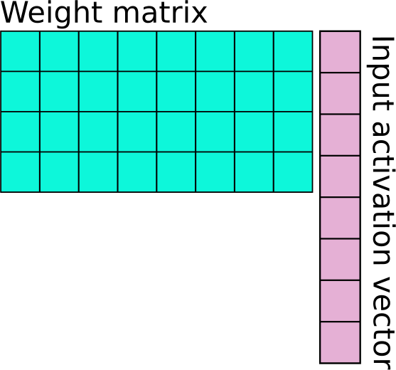
Essentially, the stream MVU is a subset of batch MVU. The stream MVU consists of a control unit and a number of processing elements (PEs). Each PE is made up of a number of SIMD units. The degree of parallelism in the MVU is determined by the number of PEs and SIMDs/PE. Consider the 4x8 weight matrix (MatrixH = 4, MatrixW = 8) and a 8x1 input activation shown in Fig. 1
 |
|---|
| Fig. 1 Weight matrix and input activation vector. |
FINN MVU Parallelism
For a fully parallel implementation of multiplying the matrix and vector in Fig. 1, the number of PEs and SIMDs/PE needs to be equal to MatrixH and MatrixW, respectively. Each PE will compute the product of the corresponing row and input vector. If the number of PEs or SIMDs/PE are lower, this results in a folded architecture. For e.g., if PE=MatrixH and SIMD=MatrixW/2, this means that each PE will process multiply the first four elements of each corresponding row with the first four elements of the input vector in a given clock cycle before repeating the operation for the next four elements, resulting in what is referred to as the synapse folding (SF) factor of two. The outputs are accumulated until the full multiplication is complete.
In case the number of PEs < MatrixH, this results in a further folding factor, referred in FINN as neuron folding (NF). For e.g., assume PE=MatrixH/2 and SIMD=MatrixW/2. This means there are only 2 PEs and 4 SIMDs. The PEs will first multiple the first two rows with corresponding values of the input vector. The input vector will be re-used for the next clock cycle as the PEs use the next two rows. In this case, SF=2 and NF=2.
FINN MVU Architecture
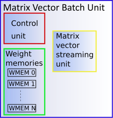
The batch unit uses the stream unit and burned-in weights along with a simple control unit to regulate the reading of weights. The inputs of both the batch and stream MVUs are compliant to the AXI stream protocol. A block diagram of the batch unit is shown in Fig. 2.
 |
|---|
| Fig. 2 MVU batch unit. |
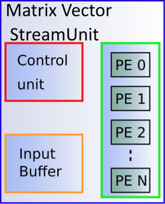
The stream unit’s block diagram is given in Fig. 3 where the input buffer is used to store the input activation in case it needs to be re-used for the case where NF>1.
 |
|---|
| Fig. 3 MVU stream unit. |
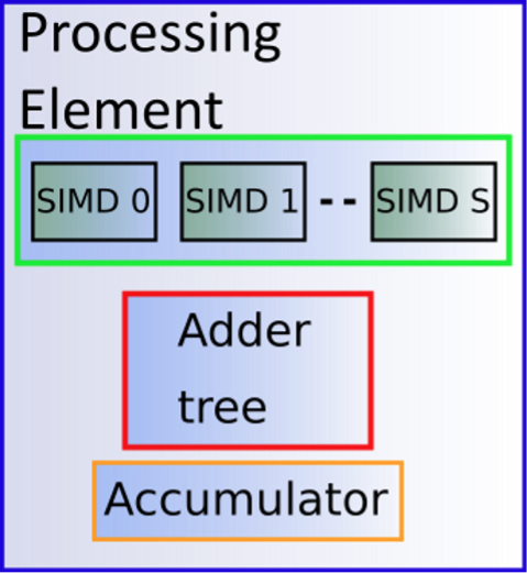
Within each PE, there are a number of SIMD blocks, an adder tree and an accumulator for the case when SF>1. The arrangement is shown in Fig. 4
 |
|---|
| Fig. 3 MVU PE. |
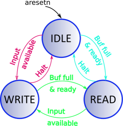
The control unit within the MVU stream unit is used to ensure compliance with the AXI stream protocol. Three key signals of the AXIS protocol is implemented, i.e., ready, valid and data. Input data is only accepted when both ready and valid are asserted while the output data is only consumed upon assertion of the corresponding ready and valid signals. This necessitates the IDLE state of Fig. 4 while the READ and WRITE states indicate the usage of the input buffer. The main matrix vector computation takes place during both the READ and WRITE states. The state diagram in Fig. 4 only shows a simplistic view of the state machine.
 |
|---|
| Fig. 3 MVU stream control unit. |
Inclusion of the IDLE state also for handling of back pressure. Furthermore, it is ensured that during the back pressure, at least one extra set of computations takes place in order to utilize idle cycles. More set of computations can also be executed if a small buffer memory is implemented to store the outputs.
FINN MVU Generic RTL Implementation
In order to implement a fully generic RTL, the design was heavily parameterized and the choice of language was SystemVerilog. SystemVerilog allows far more flexibility than Verilog or VHDL, specially in defining multi-dimensional input/output ports. The key parameters were the height and width of the weight matrix, number of PEs and SIMDs/PE, dimension of the input activation, kernel and output activation and corresponding word lengths.
Another key feature of the FINN MVU is the type of SIMD unit to implementation the multiplication of weights and input activation. There are three types of SIMD units that each handle one of the following types of inputs:
- Binary input activation and weights
- Binary weights with non-binary input activation
- Standard, non-binary weights and input activation
In the first case, SIMD calculates the XOR of the input activation and weights, while in the second case, a ‘0’ valued weight is interpreted as +1 and a ‘1’ valued weight is interpreted as -1. Through the use of parameters and generate blocks, the SIMD units were conditionally instantiated in the design, giving a high degree of flexibitily in implementing different designs.
Implementing the RTL is only part of the project. Since the key element of the work is a performance comparison between RTL and HLS, python, bash and TCL scripts were used to automate the regression test and performance analysis. The main python script, regtest_mvau.py for batch MVU and regtest_mvau_stream.py for stream MVU, defines a number of parameters for which the MVU is to be realized. Based on the given set of parameters, RTL and HLS designs are realized, simulated and synthesized. The performance numbers in terms of resource utilization (LUT, Flip-flops, BRAM, DSP), critical path delay, latency and total execution time are extracted from log files and written to an output excel file.
FINN MVU Results
Some results for the MVU batch are shown here which compares RTL and HLS runs. The various configurations for which the design was realized are shown next
| Configuration | LUT | FF | BRAM | Delay (ns) | Exec. Time (sec) | |||||
|---|---|---|---|---|---|---|---|---|---|---|
| HLS | RTL | HLS | RTL | HLS | RTL | HLS | RTL | HLS | RTL | |
| Config #1 | 1494 | 993 | 1702 | 1009 | 0 | 0 | 2.26 | 1.354 | 345 | 136 |
| Config #2 | 11106 | 12963 | 6318 | 3084 | 0 | 0 | 4.02 | 2.96 | 1313 | 227 |
| Config #3 | 2950 | 2142 | 2421 | 2018 | 32 | 16 | 2.84 | 1.91 | 516 | 178 |
| Config #4 | 11700 | 13133 | 7462 | 3389 | 32 | 16 | 4.05 | 3.84 | 1345 | 249 |
| Config #5 | 29804 | 28115 | 9661 | 2754 | 128 | 64 | 3.12 | 4.33 | 1502 | 322 |
| Config #6 | 930 | 891 | 1141 | 855 | 0 | 0 | 3.87 | 1.74 | 1055 | 113 |
| Config #7 | 2334 | 1868 | 1674 | 1500 | 0 | 0 | 3.87 | 1.74 | 1055 | 113 |
| Config #8 | 118153 | 106722 | 23454 | 8638 | 432 | 256 | 3.52 | 4.35 | 106722 | 329 |
The configurations are shown below in terms of input feature map channels (IFM Ch), input feature map dimensions (IFM Dim), output feature map channels (OFM Ch), kernel dimension (KDim), input, weight and output precision, PE and SIMD/PE
| Configs | IFM Ch | IFM Dim | OFM Ch | KDim | Inp. prec. | Weight prec. | Out. prec. | PE | SIMD/PE |
|---|---|---|---|---|---|---|---|---|---|
| Config #1 | 32 | 16 | 32 | 4 | 1 | 1 | 11 | 16 | 16 |
| Config #2 | 32 | 16 | 32 | 4 | 4 | 1 | 14 | 32 | 32 |
| Config #3 | 64 | 16 | 64 | 4 | 1 | 1 | 12 | 32 | 32 |
| Config #4 | 64 | 16 | 64 | 4 | 4 | 1 | 15 | 32 | 32 |
| Config #5 | 64 | 16 | 64 | 4 | 4 | 4 | 16 | 32 | 32 |
| Config #6 | 8 | 8 | 8 | 4 | 4 | 1 | 12 | 8 | 8 |
| Config #7 | 8 | 8 | 8 | 4 | 4 | 4 | 15 | 8 | 8 |
| Config #8 | 64 | 32 | 128 | 4 | 4 | 4 | 16 | 64 | 64 |
FINN MVU Automatic Documentation
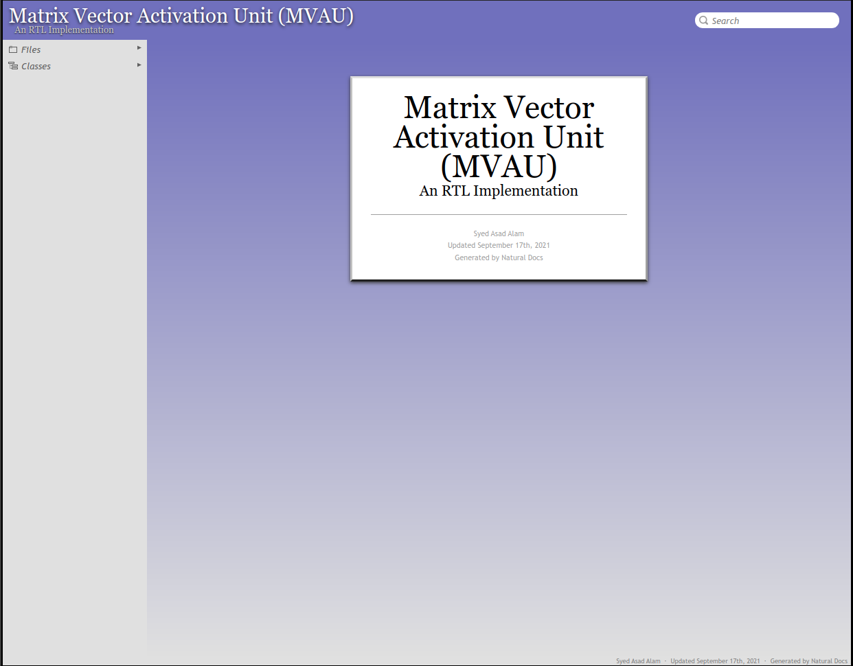
Automatic documentation based on Doxygen is not available for SystemVerilog. Adapting Doxygen for SystemVerilog is non-trivial. On the other hand, NaturalDocs presents a simplified way of extending it to include additional languages. The generation of documentation was automated using Travis CI and is available at (here)[https://asadalam.github.io/FINN_MatrixVector_RTL/]. Fig. 5 shows an image of the landing page.
 |
|---|
| Fig. 3 Automatic documentation landing page. |
FINN MVU RTL Repository
The repository for the RTL is available here. The README.md at the repository describes the organization and how the repo can be hosted.