Kria™ KR260 Robotics Starter Kit |
Machine Vision Camera Tutorial |
Hardware Architecture of the Platform
Introduction
This section describes the design implemented in the programmable logic (PL). The following figure shows the top-level hardware architecture of the reference design.
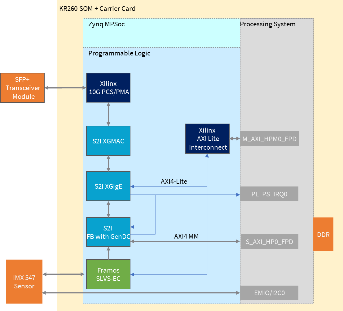
At a high level, the design comprises four pipelines:
Capture/Input pipeline: This comprises pipelines through which video data is captured.
Capture images from a file source (PS)
SLVS-EC capture pipeline (PL)
Image Sensor Processing (ISP) pipeline: This comprises functions to improve image quality.
ISP for color stream (PL)
ISP for mono stream (PL)
Display/Output pipeline: This comprises pipelines through which video data is output.
Display port as sink for output images (PS)
10G Ethernet pipeline (PL)
Accelerator pipeline: This comprises overlay accelerator functions integrated into the platform using AMD Vitis™.
The Pre-Process block modifies the input data as required by the Defect Detection function (PL).
The Defect Detection block identifies defects in a mango (PL + PS).
Both Pre-Process and Defect Detection use AMD Vitis™ Vision Library functions.
NOTE: The PS interconnects in the figure are conceptual.
Capture Pipeline
SLVS-EC Capture
A capture pipeline receives video frames from an external source and writes it into memory or streams it to another IP. The following figure shows the SLVS-EC receive capture pipeline.
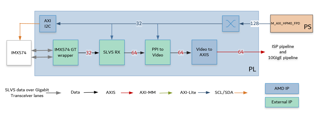
This pipeline consists of four components: two that are controlled by the application processing unit (APU) using an AXI4-Lite based register interface, one is controlled by the APU using an Inter-integrated Circuit (I2C) register interface, and one is configured statically.
The Sony IMX547 CMOS active pixel image sensor sends sensor data to the SLVS RX IP through a two-lane Gigabit Transceiver (GT) interface. It is controlled and programmed using an I2C interface using an AXI I2C controller in the PL. The Framos Sensor Module hosts the Sony IMX547 camera sensor and connects to the KR260 carrier card using a flex cable and Framos Sensor Adaptor (FSA). For more information, refer to MV Camera Sensor.
The Framos SLVS-EC RX IP Core is a receiver that handles the byte-to-pixel conversion of the incoming sensor data stream. The IP Core provided by Framos encompasses AMD GTs and the logic to process the sensor image and provide it on Parallel Pixel Interface (PPI). For more information, refer to FRAMOS SLVS-EC RX IP CORE.
The Framos PPI to Video IP Core converts the PPI data to a parallel video stream.
The LogiCORE™ IP Video In to AXI4-Stream is designed to interface to video data (clocked parallel video data with synchronization signals — active video with either syncs, blanks, or both) and convert it to the AXI4-Stream Video Protocol Interface. For more information, refer to Video In to AXI4-Stream IP Product Guide.
The IPs in this pipeline are configured to transport 4 ppc at 237.6 MHz.
An AXI4-Stream Broadcaster IP is used in the PL to broadcast 64-bit AXIS Video data from the SLVS_EC pipeline to the ISP pipeline and 10GigE pipeline.
Image Sensor Processing (ISP) Pipeline
The ISP pipeline converts the sensor data to Y8 format, resizes the image to 1920x1080p, and writes it to memory. The acceleration pipeline reads these frames. The following figure shows the ISP pipeline.
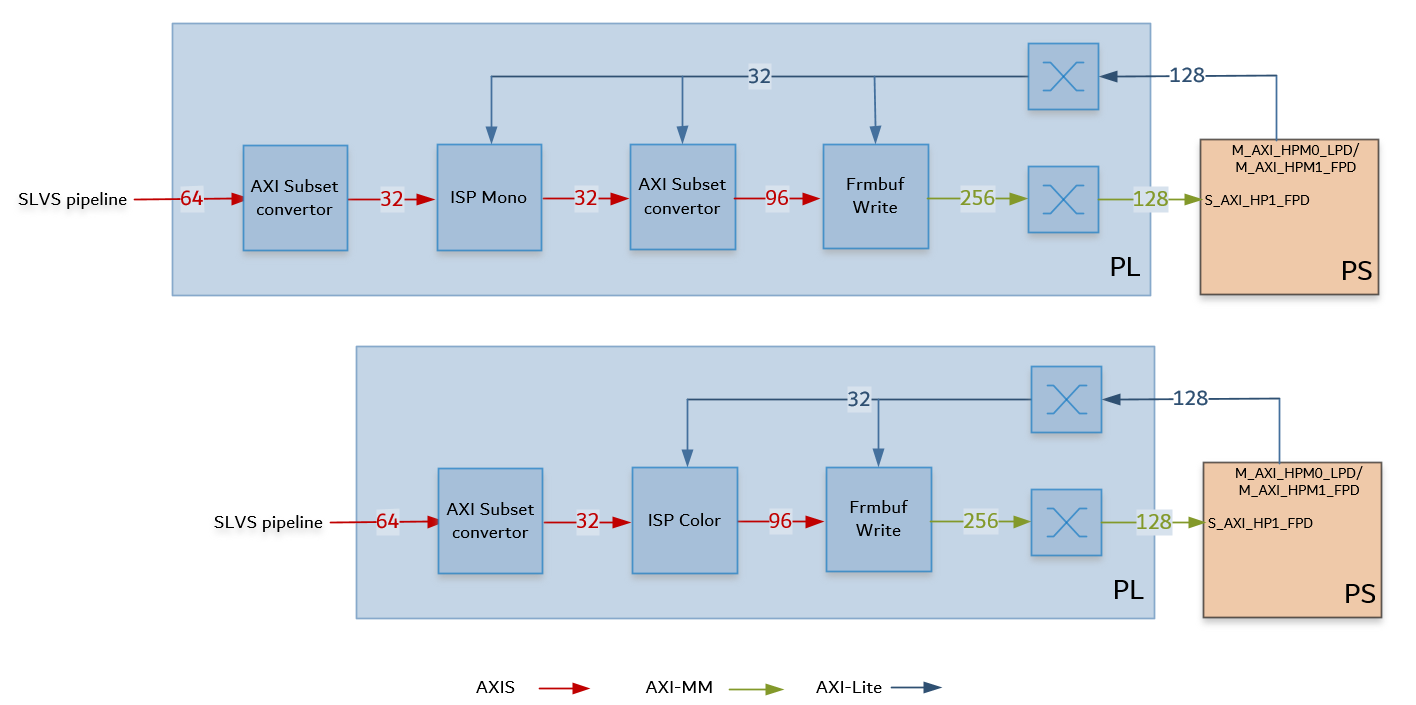
The AXI subset converter is a statically configured IP core that converts the 64-bit AXI4-Stream from the capture pipeline to a 32-bit AXI4-Stream output data by dropping the least significant bit (LSB) of each data word. The most significant bits carry the relevant information.
The ISP function from the AMD Vitis™ Vision libraries is a collection of functions that enhances the overall visual quality of the raw image from the sensor.
Functions implemented for color sensor:
Gain Control
Demosaicing
Auto white balancing
Color correction
Gamma correction
Resizing to 1920x1080
For color, the raw image is converted to BGR8 format, 24 bits per pixel, 96-bits for 4ppc.
Functions implemented for mono sensor:
Gain Control
Gamma correction
Resizing to 1920x1080
For mono, the raw image is converted to Y8 format, 8 bits per pixel, 32-bits for 4ppc.
The AXI subset converter is a statically configured IP core that converts the 32-bit AXI4-Stream input data to a 96-bit AXI4-Stream output data by adding zeros to the most significant bit (MSB) of each data word. At four ppc, the AXI4-Stream width is 96-bits. This is applicable to the mono pipeline only.
The video frame buffer takes AXI4-Stream (RGB8 for color and Y8 for mono) input data and converts it to AXI4-MM format, which is written to memory. The memory-mapped AXI interface is connected to the S_AXI port of the PS. For each video frame transfer, an interrupt is generated. A general-purpose I/O (GPIO) resets the IP. For more information, refer to the Video Frame Buffer Read and Video Frame Buffer Write LogiCORE IP Product Guide.
All the IPs in this pipeline can transport 4 ppc at 237.6 MHz.
Output Pipeline — 10GigE
The 10GigE pipeline transfers the captured raw data to the host system using an SFP connection. The following block diagram shows the 10GigE Vision pipeline. The major blocks in the pipeline are provided by Sensor to Image (S2I).
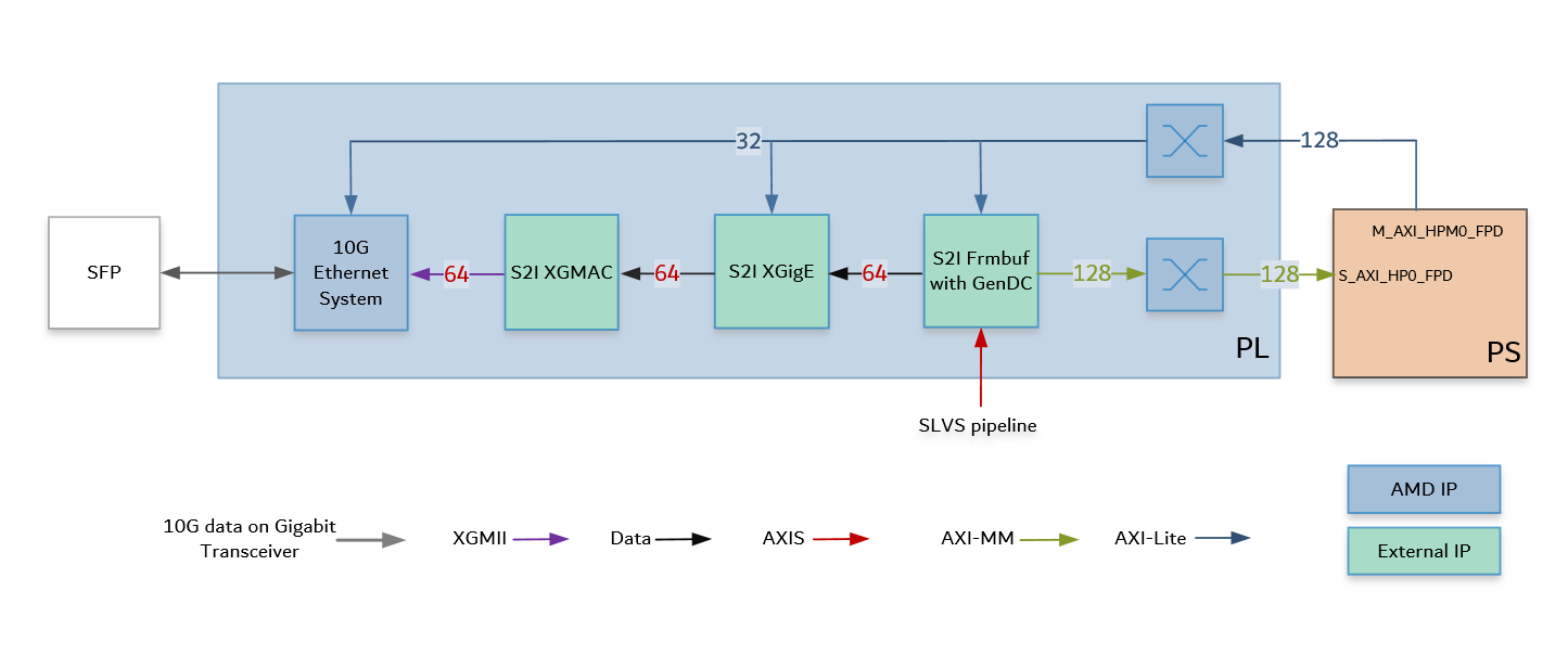
The pipeline consists of the following modules:
Framebuffer with Gen DC: The AXI4 stream output of the SLVS-EC IP pipeline is forwarded to Framebuffer IP. This IP buffers the image data in memory. The Framebuffer also prepares the data to be sent in GenICam GenDC format, which allows for sending different types of data (for example, raw image, preprocessed image, and metadata) in a data container. It sends ethernet packet size data chunks to the 10GigE packet composer (XGigE).
XGigE core: This module handles all the low-level networking features to the rest of the system. It forms the GigE Vision stream channel and provides networking interface for the CPU system.
10GigE MAC: This module implements the Media Access Controller (MAC) and sends data to the PHY over XGMII (Media-Independent-Interface).
The AMD 10G/25G High Speed Ethernet Subsystem is configured to support the physical coding sublayer/physical medium attachment (PCS/PMA) functions at 10G speeds. The IP implements the PHY layer of the 10GigE protocol and transmits the packetized sensor data on the Gigabit transceiver.
Resource Utilization after Synthesis
| Blocks | LUT | FF | Block RAM | URAM | DSP | GT |
|---|---|---|---|---|---|---|
| SLVS-EC | 1886 | 2948 | 22.5 | 0 | 0 | 2 |
| 10GigE IPs | 13889 | 18809 | 35 | 0 | 0 | 0 |
| Ethernet System | 2745 | 5010 | 0 | 0 | 0 | 1 |
| ISP-Color | 24530 | 24744 | 26 | 14 | 166 | 0 |
| ISP-Mono | 8939 | 9787 | 9 | 6 | 26 | 0 |
References
To get the 10GigE IP license, contact Sensor to Image S2I.
Refer to the S2I Release note.