2.2. FFT/iFFT
The DSPLib contains one FFT/iFFT solution. This is a single channel, decimation in time (DIT) implementation. It has configurable point size, data type, forward/reverse direction, scaling (as a shift), cascade length, static/dynamic point size, window size, interface api (stream/window) and parallelism factor. Table 6 lists the template parameters used to configure the top level graph of the fft_ifft_dit_1ch_graph class.
2.2.1. Entry Point
The graph entry point is the following:
xf::dsp::aie::fft::fft_ifft_dit_1ch_graph
2.2.2. Supported Types
The data type to the FFT is controlled by the template parameter TT_DATA. This may take one of 3 choices: cint16, cint32 or cfloat. This selection applies to both input data and output data. The template parameter TT_TWIDDLE may take one of two values, cint16 or cfloat, but currently this value is forced by the choice of TT_DATA, so TT_TWIDDLE must be set to cint16 for TT_DATA = cint16 or cint32 and TT_TWIDDLE must be set to cfloat when TT_DATA=cfloat.
2.2.3. Template Parameters
To see details on the template parameters for the FFT, see API Reference Overview.
2.2.4. Access functions
To see details on the access functions for the FFT, see API Reference Overview.
2.2.5. Ports
To see details on the ports for the FFT, see API Reference Overview. Note that the number and type of ports are determined by the configuration of template parameters.
2.2.6. Design Notes
2.2.6.1. Dynamic Point Size
The FFT supports dynamic (run-time controlled) point sizes. This feature is available when the template parameter TP_DYN_PT_SIZE is set. When set to 0 (static point size) all data will be expected in frames of TP_POINT_SIZE data samples, though multiple frames may be input together using TP_WINDOW_VSIZE. When set to 1 (dynamic point size) each _window_ must be preceeded by a 256bit header to describe the run-time parameters of that window. Note that TP_WINDOW_VSIZE described the number of samples in a window so does not include this header. The format of the header is described in Table 5. When TP_DYN_PT_SIZE =1 TP_POINT_SIZE describes the maximum point size which may be input.
| Field name | Location (TT_DATA sample) | Description |
|---|---|---|
| Direction | 0 (real part) | 0 (inverse FFT) 1 (forward FFT) |
| Point size (radix2 stages) | 1 (real part) | Point size described as a power of 2. E.g. 5 described a point size of 32. |
| Reserved | 2 | reserved |
| Status (output only) | 3 (real part) | 0 = legal point size, 1 = illegal point size |
The locations are set to suit TT_DATA type. That is, for TT_DATA=cint16, direction is described in the first cint16 (real part) of the 256 bit header and point size is described in the real part of the second cint16 value. Similarly, for TT_DATA=cint32, the real part of the first cint32 value in the header holds the direction field and the second cint32 value’s real part holds the Point size (radix2) field.
Note that for TT_DATA=cfloat, the values in the header are expected as cfloat and are value-cast (not reinterpret-cast) to integers internally. The output window also has a header. This is copied from the input header except for the status field, which is inserted. The status field is ignored on input. If an illegal point size is entered, the output header will have this field set to a non-zero value and the remainder of the output window is undefined.
2.2.6.2. Super Sample Rate Operation
While the term Super Sample Rate strictly means the processing of more than one sample per clock cycle, in the AIE context it is taken to mean an implementation using parallel kernels to improve performance at the expense of additional resource use. In the FFT, SSR operation is controlled by the template parameter TP_PARALLEL_POWER. This parameter is intended to improve performance and also allow support of point sizes beyond the limitations of a single tile. Diagram Figure 2: Applying Design Constraints shows an example graph with TP_PARALLEL_POWER set to 2. This results in 4 subframe processors in parallel each performing an FFT of N/2^TP_PARALLEL_POWER point size. These subframe outputs are then combined by TP_PARALLEL_POWER stages of radix2 to create the final result. The order of samples is described in the note for TP_API above.
The parameter TP_PARALLEL_POWER allows a trade of performance for resource use in the form of tiles used. The following table shows the tile utilization versus TP_PARALLEL_POWER assuming that all widgets co-habit with FFT processing kernels.
| TP_PARALLEL_POWER | Number of tiles |
|---|---|
| 0 | 1 |
| 1 | 4 |
| 2 | 12 |
| 3 | 32 |
| 4 | 80 |
2.2.6.2.1. Super Sample Rate Sample to Port Mapping
When Super Sample Rate operation is used, data is input and output using multiple ports. These multiple ports on input or output act as one channel. The mapping of samples to ports is that each successive sample should be passed to a different port in a round-robin fashion, e.g. with TP_SSR set to 3, sample 0 should be sent to input port 0, sample 1 to input port 1, sample 2 to input port 2, sample 3 to input port 0 and so on.
2.2.6.3. Scaling
Scaling in the FFT is controlled by the TP_SHIFT parameter which describes how many binary places by which to shift the result to the right, i.e. only power-of-2 scaling values are supported. The FFT implementation does not implement the 1/N scaling of an IFFT directly, but this may be configured via TP_SHIFT. Internal to the FFT, for cint16 and cint32 data, an data type of cint32 is used for temporary value. After each rank, the values are scaled by only enough to normalize the bit growth caused by the twiddle multiplication (i.e., 15 bits), but there is no compensation for the bit growth of the adder in the butterfly operation. No scaling is applied at any point when the data type is cfloat. Setting TP_SHIFT to any value other than 0 when TT_DATA is cfloat will result in an error. In the case of TP_PARALLEL_POWER > 0 for cint16, the streams carrying data between subframe processors and the combiner stages carry cint16 data so as to allow for high performance. In this case, the scaling value applied to each subframe processor is (TP_SHIFT-TP_PARALLEL_POWER) (if positive and 0 if not). Each combiner stage will have a shift of 1 is applied, to compensate for the bit growth of 1 in the stage’s butterfly, if there is adequate TP_SHIFT to allow for this, or 0 if there is not. For example, with an FFT configured to be POINT_SIZE=1024, DATA_TYPE=cint16, PARALLEL_POWER=2 and TP_SHIFT=10, there will be 4 subframe processors and 2 further ranks of 4 combiners. The 4 subframe processors will all have a local TP_SHIFT of 10-2 = 8 applied and each of the combiners will have a local TP_SHIFT of 1 applied. This scheme is designed to preserve as much accuracy as possible without compromising performance. If better accuracy or noise performance is required, this may be achieved at the expense of throughput by using TT_DATA=cint32.
2.2.6.4. Saturation
Distortion caused by saturation will be possible for certain configurations of the FFT. For instance, with DATA_TYPE=cint32, it is possible for the sample values within the FFT to grow beyond the range of int32 values. In the final stage when TP_SHIFT is applied, saturation is also applied. Similarly, if the FFT is configured for DATA_TYPE=cint16, but insufficient scaling (TP_SHIFT) is applied, then sample values may exceed the range of int16 and so these too will be saturated in the final stage. Note that for cases with TP_PARALLEL_POWER>1, saturation is applied at the end of each subframe processor and also in each combiner, so for data sets which cause saturation even in the subframe processor, the output will likely not match the output of an FFT model. For DATA_TYPE=cfloat, the FFT performs no scaling, nor saturation. Any saturation effects will be due to the atomic float operations returning positive infinity, negative infinity or NaN.
2.2.6.5. Constraints
The FFT design has large memory requirements for data buffering and twiddle storage. Constraints may be necessary to fit a design or to achieve high performance, such as ensuring FFT kernels do not share tiles with other FFT kernels or user kernels. To apply constraints you must know the instance names of the internal graph hierarchy of the FFT. See Figure 2: Applying Design Constraints below.
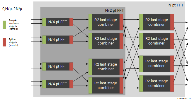
Figure 2: Applying Design Constraints
The FFT class is implemented as a recursion of the top level to implement the parallelism. The instance names of each pair of subgraphs in the recursion are FFTsubframe(0) and FFTsubframe(1). In the final level of recursion, the FFT graph will contain an instance of either FFTwinproc (for TP_API = 0) or FFTstrproc (when TP_API=1). Within this level there is an array of kernels called m_fftKernels which will have TP_CASC_LEN members.
The stream to window conversion kernels on input and output to the fft subframes are at the same level as m_fftKernels and are called m_inWidgetKernel and m_outWidgetKernel respectively. Each level of recursion will also contain an array of radix2 combiner kernels and associated stream to window conversion kernels. These are seen as a column of kernels in the above figure. Their instance names are m_r2Comb[] for the radix2 combiners and m_combInKernel[] and m_combOutKernel[] for the input and output widget kernels respectively.
Examples of constraints: For TP_PARALLEL_POWER=2, to set the runtime ratio of the 3rd of 4 subframe FFTs, the constraint could look like this:
runtime<ratio>(myFFT.FFTsubframe[1].FFTsubframe[0].FFTstrproc.m_kernels[0]) = 0.9; //where myFFT is the instance name of the FFT in your design.
For the same example, to ensure that the second radix2 combiner kernel in the first column of combiners and its input widget do not share a tile, the constraint could look like this:
not_equal(location<kernel>(myFFT.FFTsubframe[0].m_combInKernel[1]),location<kernel>( myFFT.FFTsubframe[0].m_r2Comb[1]));
For large point sizes, e.g. 65536, the design is large, requiring 80 tiles. With such a large design, the Vitis AIE mapper may time out due to there being too many possibilities of placement, so placement constraints are recommended to reduce the solution space and so reduce the time spent by the Vitis AIE mapper tool to find a solution. Example constraints have been provided in the test.hpp file for the fft_ifft_dit_1ch, i.e in: L2/tests/aie/fft_ifft_dit_1ch/test.hpp.
2.2.7. Code Example including constraints
The following code block shows example code of how to include an instance of the fft_ifft_dit_1ch graph in a super-graph and also how constraints may be applied to kernels within the FFT graph. Note that in this example not all kernels within the fft_ifft_dit_1ch graph are subject to location constraints. It is sufficient for the mapper to find a solution in this case by constraining only the r2comb kernels.
#define LOC_XBASE 0
#define LOC_YBASE 0
#define DATA_TYPE cint16
#define TWIDDLE_TYPE cint16
#define POINT_SIZE 65536
#define FFT_NIFFT 1
#define SHIFT 17
#define CASC_LEN 1
#define DYN_PT_SIZE 0
#define WINDOW_VSIZE 65536
#define API_IO 1
#define PARALLEL_POWER 4
#include <adf.h>
#include "fft_ifft_dit_1ch_graph.hpp"

class myFft : public adf::graph
{
public:
  static constexpr int kParFactor = 1<<PARALLEL_POWER;
  adf::port<input> in[kParFactor];
  adf::port<output> out[kParFactor];
  xf::dsp::aie::fft::dit_1ch::fft_ifft_dit_1ch_graph<DATA_TYPE, TWIDDLE_TYPE, POINT_SIZE, FFT_NIFFT, SHIFT, CASC_LEN,
                                                     DYN_PT_SIZE, WINDOW_VSIZE, API_IO, PARALLEL_POWER>
                                                     fftGraph;
  myFft()
  {
    //make connections
    for (int i=0; i< kParFactor; i++)
    {
      connect<>(in[i], fftGraph.in[i]);
      connect<>(fftGraph.out[i], out[i]);
    }
    //constraint location to allow mapper to complete before timeout
    #if (POINT_SIZE==65536)
    for (int lane=0; lane<kParFactor; lane++)
    {
      location<kernel>(fftGraph.m_r2Comb[lane]) = tile(LOC_XBASE + lane * 2, LOC_YBASE + CASC_LEN + 4);
      }

      for (int lane=0; lane<kParFactor/2; lane++)
      {
              location<kernel>(fftGraph.FFTsubframe0.m_r2Comb[lane]) =
                  tile(LOC_XBASE + lane * 2, LOC_YBASE + CASC_LEN + 3);
              location<kernel>(fftGraph.FFTsubframe1.m_r2Comb[lane]) =
                  tile(LOC_XBASE + lane * 2 + 16, LOC_YBASE + CASC_LEN + 3);
      }

      for (int lane=0; lane<kParFactor/4; lane++)
      {
              location<kernel>(fftGraph.FFTsubframe0.FFTsubframe0.m_r2Comb[lane]) =
                  tile(LOC_XBASE + lane * 2, LOC_YBASE + CASC_LEN + 2);
              location<kernel>(fftGraph.FFTsubframe0.FFTsubframe1.m_r2Comb[lane]) =
                  tile(LOC_XBASE + lane * 2 + 8, LOC_YBASE + CASC_LEN + 2);
              location<kernel>(fftGraph.FFTsubframe1.FFTsubframe0.m_r2Comb[lane]) =
                  tile(LOC_XBASE + lane * 2 + 16, LOC_YBASE + CASC_LEN + 2);
              location<kernel>(fftGraph.FFTsubframe1.FFTsubframe1.m_r2Comb[lane]) =
                  tile(LOC_XBASE + lane * 2 + 24, LOC_YBASE + CASC_LEN + 2);
          }
      }

      for (int lane=0; lane<kParFactor/8; lane++)
      {
              location<kernel>(fftGraph.FFTsubframe0.FFTsubframe0.FFTsubframe0.m_r2Comb[lane]) =
                  tile(LOC_XBASE + lane * 2, LOC_YBASE + CASC_LEN + 1);
              location<kernel>(fftGraph.FFTsubframe0.FFTsubframe0.FFTsubframe1.m_r2Comb[lane]) =
                  tile(LOC_XBASE + lane * 2 + 4, LOC_YBASE + CASC_LEN + 1);
              location<kernel>(fftGraph.FFTsubframe0.FFTsubframe1.FFTsubframe0.m_r2Comb[lane]) =
                  tile(LOC_XBASE + lane * 2 + 8, LOC_YBASE + CASC_LEN + 1);
              location<kernel>(fftGraph.FFTsubframe0.FFTsubframe1.FFTsubframe1.m_r2Comb[lane]) =
                  tile(LOC_XBASE + lane * 2 + 12, LOC_YBASE + CASC_LEN + 1);
              location<kernel>(fftGraph.FFTsubframe1.FFTsubframe0.FFTsubframe0.m_r2Comb[lane]) =
                  tile(LOC_XBASE + lane * 2 + 16, LOC_YBASE + CASC_LEN + 1);
              location<kernel>(fftGraph.FFTsubframe1.FFTsubframe0.FFTsubframe1.m_r2Comb[lane]) =
                  tile(LOC_XBASE + lane * 2 + 20, LOC_YBASE + CASC_LEN + 1);
              location<kernel>(fftGraph.FFTsubframe1.FFTsubframe1.FFTsubframe0.m_r2Comb[lane]) =
                  tile(LOC_XBASE + lane * 2 + 24, LOC_YBASE + CASC_LEN + 1);
              location<kernel>(fftGraph.FFTsubframe1.FFTsubframe1.FFTsubframe1.m_r2Comb[lane]) =
                  tile(LOC_XBASE + lane * 2 + 28, LOC_YBASE + CASC_LEN + 1);
      }

      #endif //(POINT_SIZE == 65536)
    }
  };//end of class