Vitis Platform Flow Example: Adding a Raspberry Pi Camera to SmartCam’s Platform
This example takes SmartCam’s platform, kv260_ispMipiRx_vcu_DP, removes its MIPI ISP and audio IPs, and adds Raspberry Pi support instead. Then you add in the DPU accelerator overlay for the SmartCam application. Functionally, this allows the SmartCam application to take the image sensor input from the Raspberry Pi Camera on J9 instead of the AP1305 sensors on J7.
The tutorial first regenerates the platform with the Raspberry Pi pipeline, creating its corresponding bitstream and device tree artifacts. You then test those artifacts with the Raspberry Pi Camera to display Raspberry Pi capture on the monitor without any accelerator functions. Then you take the platform and add a DPU accelerator, and retest the firmware with accelerator function added in; the accelerator function creates a blue bounding box on faces detected.
This example is targeted for the 20022.1 release on Ubuntu 22.04 for KV260.
Prerequisites and Hardware Setup
You must have gone through tutorial on running SmartCam on the KV260 Ubuntu 22.04, based on tool version 2022.1, so that you understand how to program the SD card and basics of running an application on the KV260. The example also uses SmartCam docker container to provide the drivers needed.
The hardware setup is similar to that of SmartCam, except you do not need to the IAS sensor in J7 but a Raspberry Pi Camera on J9 instead. This tutorial has been tested with the Rasberry Pi Camera V2 from element14.
This example is based on 2022.1 releases, so be sure to use 2022.1 tools, BSPs, repositories, and so on.
Generating the Platform
Obtaining the Platform
Because you are altering the SmartCam platform, kv260_ispMipiRx_vcu_DP, you first need to get the platform. Detailed tutorial is at Creating Vitis Platform. Here are the specific commands to use to generate the platform:
git clone --recursive --branch xlnx_rel_v2022.1 https://github.com/Xilinx/kria-vitis-platforms.git
cd kria-vitis-platforms/kv260/
In this page, the preceding directory is referred to as $kv260-vitis .
make platform PFM=kv260_ispMipiRx_vcu_DP
cd $kv260-vitis/platforms/vivado/kv260_ispMipiRx_vcu_DP/project/
The Vivado project is located in $kv260-vitis/platforms/vivado/kv260_ispMipiRx_vcu_DP/project/kv260_ispMipiRx_vcu_DP.xpr.
In Vivado, open the .xpr project.
Obtaining the isp_single IP
In this example, you use a Raspberry Pi pipeline that uses a ISP block. This is a custom IP that is not present in AMD IP catalog, so you need to manually copy it to your project. This IP is found in $kv260-vitis/platforms/vivado/kv260_ispMipiRx_rpiMipiRx_DP/ip/isp_single_kv260/, this is the platform for nlp_smartvision app that has support for Raspberry Pi.
To generate the IP, use the following command:
cd $kv260-vitis/platforms/vivado/kv260_ispMipiRx_rpiMipiRx_DP/ip/isp_single_kv260/
make ip
This generates a
isppipeline.prj/folder; this is the ISP IP you use in this project.In Vivado project where you have
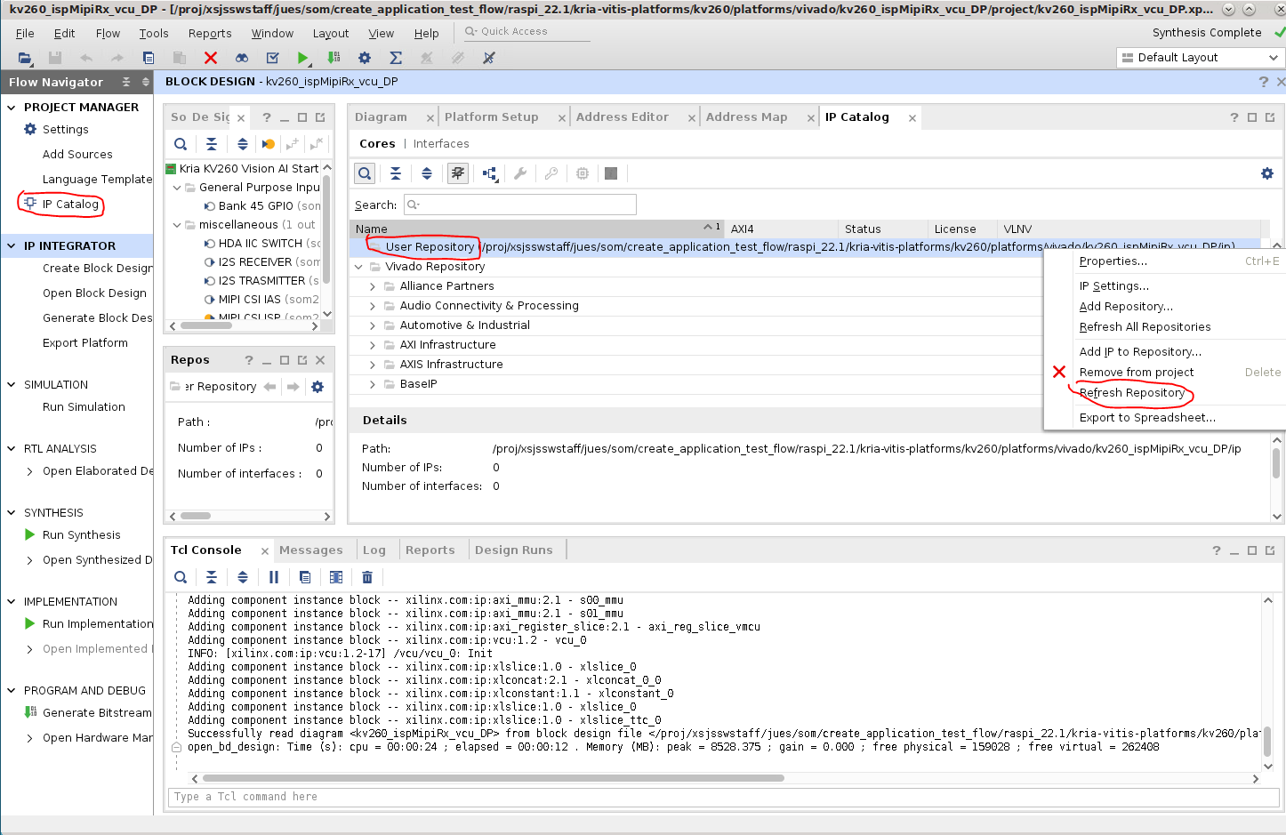
kv260_ispMipiRx_vcu_DP.xpropened, click Project Manager -> IP Catalog, and notice the user repository. This is where you copy theisp_single_kv260/IP to which is located in$kv260-vitis/platforms/vivado/kv260_ispMipiRx_vcu_DP/ip/.Copy the single_isp IP over:
cd $kv260-vitis/
cp platforms/vivado/kv260_ispMipiRx_rpiMipiRx_DP/ip/isp_single_kv260/ platforms/vivado/kv260_ispMipiRx_vcu_DP/ip/ -rf
Then, refresh the repo:
Importing the Raspberry Pi Pipeline
Next, import the Raspberry Pi pipeline that replaces the original ISP pipeline in kv260_ispMipiRx_vcu_DP.
Download the source capture_pipeline_raspi.tcl, and source it in the Vivado Tcl Console.
source capture_pipeline_raspi.tcl
Next, click Flow Navigator -> IP Integrator -> Open Block Design, and then in Tcl Console, type in the following to instantiate the subblock of the ISP pipeline for Raspberry Pi:
create_hier_cell_capture_pipeline_raspi ./ raspi_pipeline
This creates a new, unconnected block of the Raspberry Pi ISP pipeline in the existing block design. You can double click the block to see the component of this subblock.
NOTE: You can find pin assignment for Raspberry Pi in mipi_csi2_rx_subsyst_0 by double clicking the IP and navigating to the Pin Assignment tab.
Optional: Generating capture_pipeline_raspi.tcl
The following steps show how to generate capture_pipeline_raspi.tcl in the platform used for Raspberry Pi-supported NLP application. This is not required because we have provided the file is already provided, but instructions to show you how it was imported from one project to another are also provided.
cd $kv260-vitis
make platform PFM=kv260_ispMipiRx_rpiMipiRx_DP
In Vivado, open
platforms/vivado/kv260_ispMipiRx_rpiMipiRx_DP/project/kv260_ispMipiRx_rpiMipiRx_DP.xpr. Click IP Integrator -> Open Block Design.Double click capture_pipeline_raspi, double click mipi_csi2_rx_subsyst_0, select the Shared Logic tab, change to Include Shared Logic in Core, and click okay. This removes the
pll_lock_inandclkoutphy_inpins. Also remove the unconnected pins from the capture_pipeline_raspi hierarchy’s pin list.In the Vivado Tcl Console, enter:
write_bd_tcl -hier_blks [get_bd_cells capture_pipeline_raspi] capture_pipeline_raspi.tclThis generates
capture_pipeline_raspi.tcl.
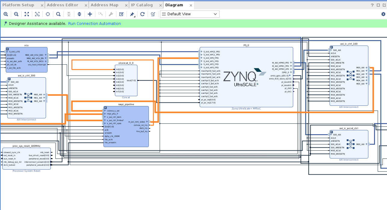
Updating the Block Design
Next, you replace the capture_pipeline with this raspi_pipeline. Most of the signals can be replaced one to one;if it is the same signal between capture_pipeline and raspi_pipeline, disconnect the signal/bus on capture_pipeline and connect other IP/interfaces to raspi_pipeline instead. At the end, click capture pipeline, and press delete” to remove it. Most of the raspi_pipeline is connected by now:
s_axi_CTRL ands_axi_ctrl_vpssare still not connected. You need to create connections for them. Find axi_ic_ctrl_300; it currently only has oneM00_AXIport connected toraspi_pipeline/s_axi_ctrl_frm_buf. Double click axi_ic_ctrl_300, and change the Number of Master Interfaces from 1 to 3: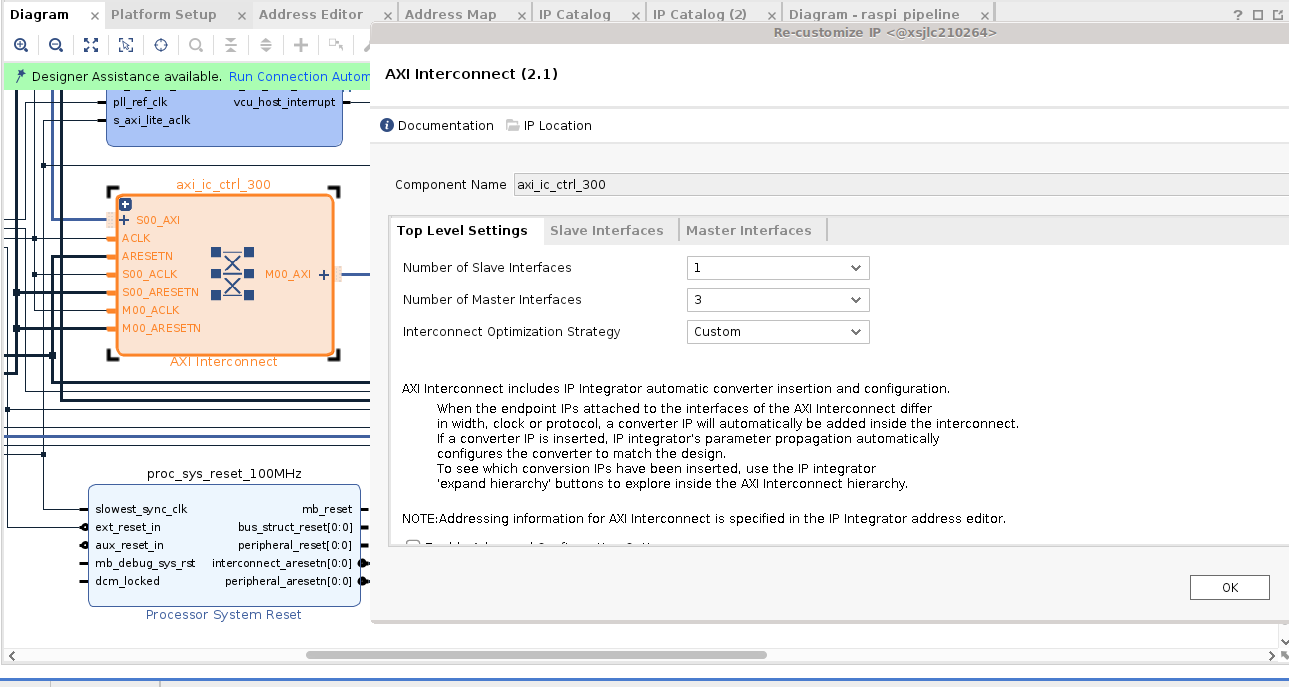
Now, connect the
ACLKandARRESETNsignals onaxi_ic_ctrl_300, and connect theM01_AXIandM02_AXIto the twos_axi portson raspi_pipeline that are still unconnected.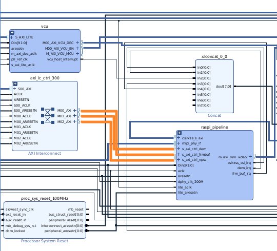
Next, you must free up an interrupt port because the raspi_pipeline has more interrupts than the
capture_pipelineyou deleted. You do not need the audio path in this experiment, so remove them. In the block design, find theAudio_ss_0block to delete them. Next, updateaxi_ic_audio_mcuto have one single slave port instead of three; this interconnect is still needed because of the address width difference between them_axi_vcu_mcu portofaxi_ic_audio_mcuand thes_axi_lpdport ofps_0. This also frees up three ports onaxi_ic_ctrl_100; double click that and change it from six master ports to three master ports.Next,
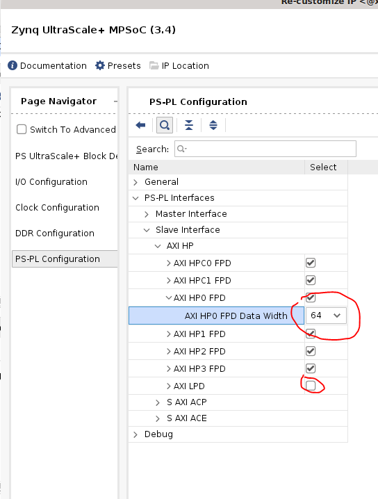
PS_0/S_AXI_HP0_FPDis currently 128 bits wide, but the new connection raspi_pipeline/m_axi_mm_video is only 64 bits. Double click PS_0, select PS-PL Configuration -> PS-PL Interfaces -> Slave Interfaces -> AXI HP -> AXI HP0 FPD, and change the AXI HP0 FPD Data Width from 128 to 64.It should look similar to the following screenshot. Click OK:
Next, connect the interrupts:
Raspberry Pi requires you to enable
HDA09via theF11pin. Right-click Add IP “Constant” with “Const Val” = 1, right click ->, create a port with “Port name” = raspi_enable, Direction = Output, Type = other. Connect them. This ensures that you enable HDA09.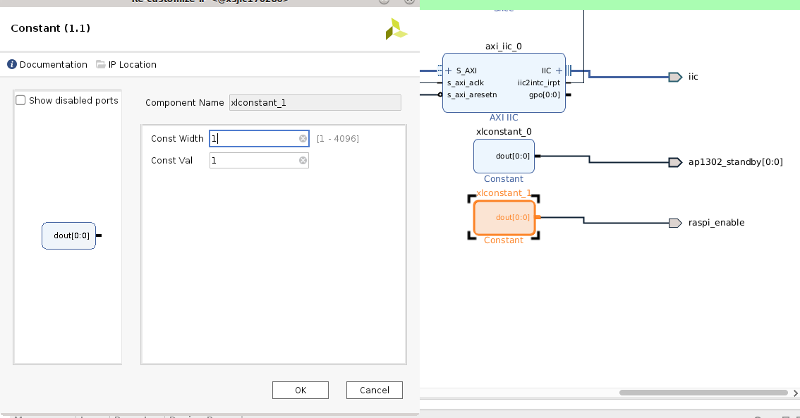
Constraint File
Reuse the constraints for MIPI PHY. Raspberry Pi requires you to enable HDA09 via the F11 pin. To add the raspi_enable constraint, add the following to prj/prj.srcs/constrs_1/imports/xdc/pin.xdc :
#Raspi Enable HDA09
set_property PACKAGE_PIN F11 [get_ports {raspi_enable}]
set_property IOSTANDARD LVCMOS33 [get_ports {raspi_enable}]
set_property SLEW SLOW [get_ports {raspi_enable}]
set_property DRIVE 4 [get_ports {raspi_enable}]
Address Map
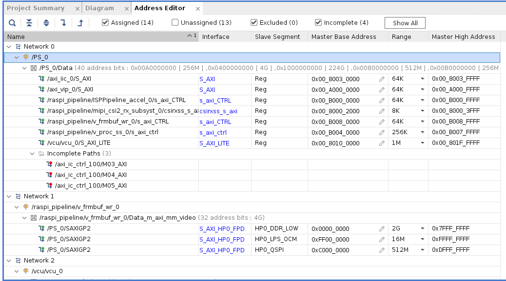
Go to the Address Editor tab, and modify the address of the ones in green boxes (see the following snapshot). First, select all the unassigned address, right click, and click assign. Then go back and modify their address and range to match the following screenshot (you can also leave the PS_0/raspi_pipeline* address as the default, just matching the range, but you then need to update .dtsi to match).
Lower the Clock Rate
Double-click clk_wiz_0, change
clk_300Mtoclkv_200M, and update theoutput frequency. The Raspberry Pi IP does meet timing at 300 MHz.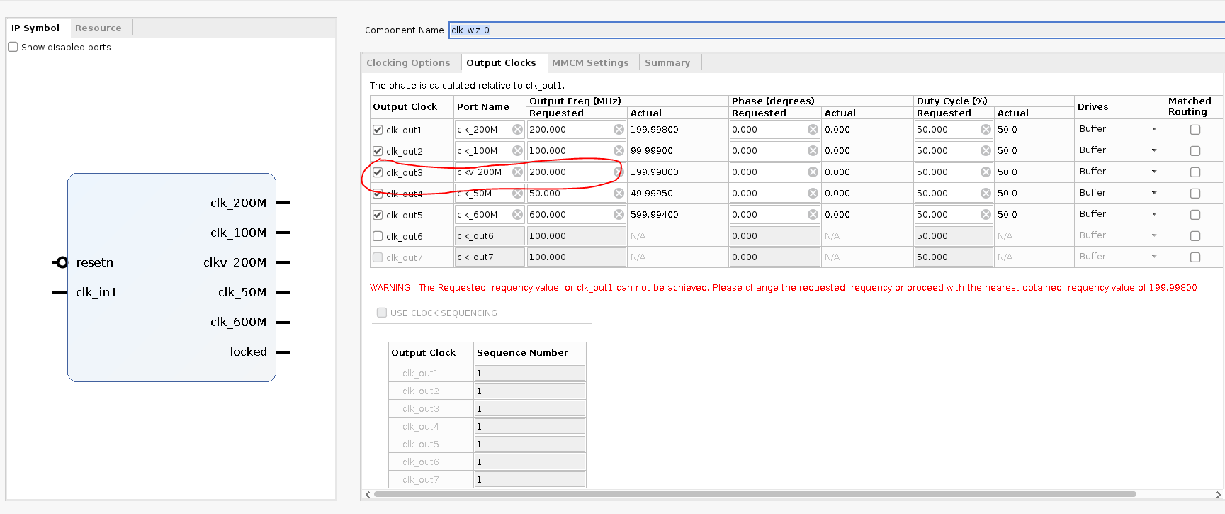
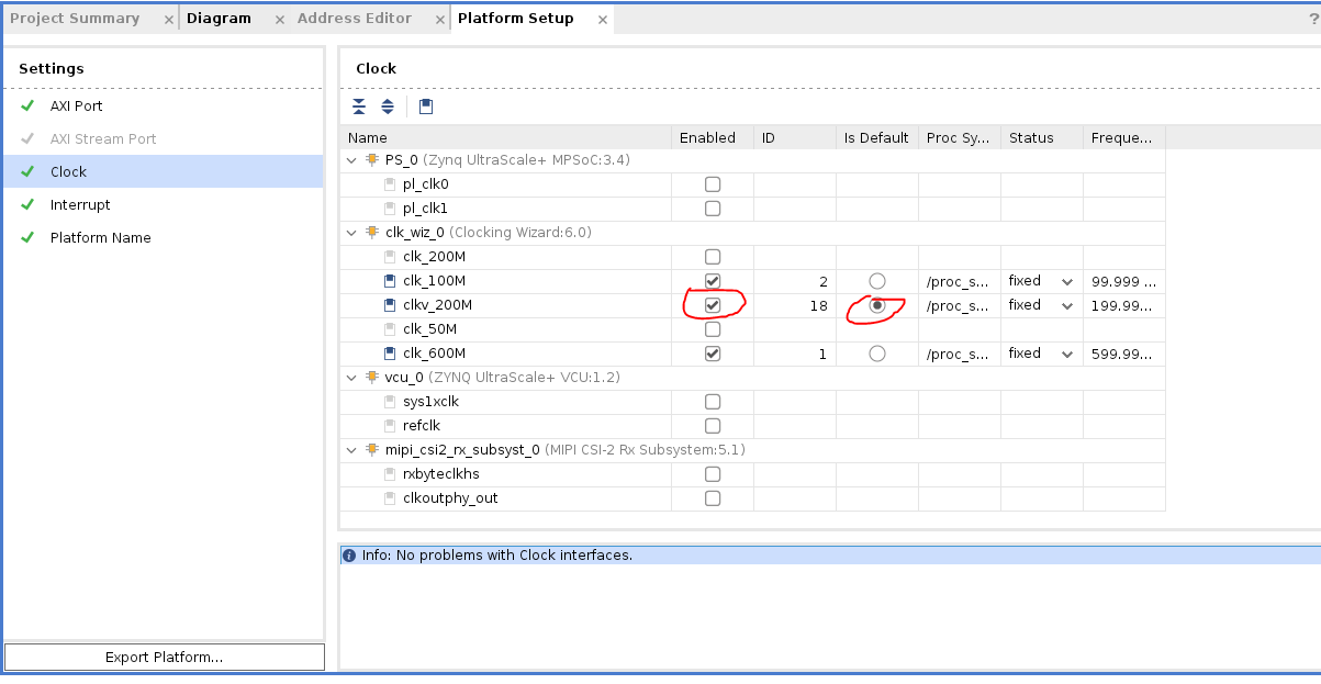
Now go to Platform Setup tab, click on “Clock” and enable the new clkv_200M and set it as default clock:
Platform Setup
Navigate to the Platform Setup tab. No changes are needed, but notice that you are keeping the same ports for accelerator insertion in Vitis.
Validate the Design
Select Tools (top tool bar) -> Validate Design. When asked if you want to add an autoa assign unassigned address segment, click No.
Generate the Wrapper
Regenerate the wrapper because you added a raspi_enable signal.
Navigate to Block Design -> sources -> Design Sources, right-click kv260_ispMipiRx_vcu_DP_wrapper, and select Remove File from Project:
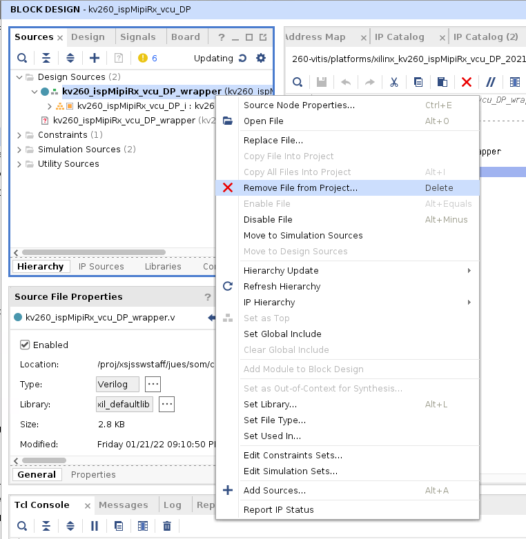
In pop-up select “Ignore and continue with invalid top module”
Block Design -> sources -> Design Sources -> right click on kv260_ispMipiRx_vcu_DP and select “Generate HDL wrapper”:
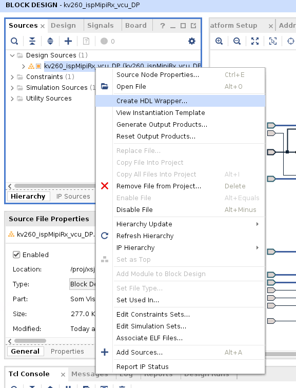
In the pop-up, select Let Vivado manage wrapper and auto-update, and click OK.
Double-click the kv260_ispMipiRx_vcu_DP_wrapper file, and raspi_enable displays as one of the outputs in the wrapper.
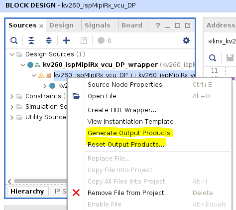
Generate the Output Products
Navigate to Block Design -> sources -> Design Sources, right-click kv260_ispMipiRx_vcu_DP_i, and select Reset Output Products. Then navigate to Block Design -> sources -> Design Sources, right-click kv260_ispMipiRx_vcu_DP_i, select Generate Output Products, select out of context per IP, and click Generate:
Generate the Bitstream
Now you are ready to generate the bitstream. To generate the bitstream, click Program and Debug -> Generate Bitstream. This process takes some time.
After the .bit file is generated, convert it to a .bit.bin file, the format that xmutil is expecting:
cd $kv260-vitis/platforms/vivado/kv260_ispMipiRx_vcu_DP/project/kv260_ispMipiRx_vcu_DP.runs/impl_1/
echo 'all:{kv260_ispMipiRx_vcu_DP_wrapper.bit}'>bootgen.bif
bootgen -w -arch zynqmp -process_bitstream bin -image bootgen.bif
mv kv260_ispMipiRx_vcu_DP_wrapper.bit.bin kv260-smartcam-raspi.bit.bin
Creating the .dtsi File
Base your .dtsi file from the SmartCam .dtsi file. Remove the ISP and audio devices, as well as ap1302 on I2C port 0.
In their stead, we will need to add the imx devices and their associated support functions. The resulting dtsi file can be found in kv260-smartcam-raspi.dtsi. There are a few things to correlate to the PL design:
Base Address
Each device in the .dtsi file needs to have the correct address corresponding to what you set in the “Address Map” section. The provided .dtsi file corresponds to the screenshot. If your address map is different, make the necessary changes.
imx_isp0 in .dtsi corresponds to ISPPipeline_accel_0
imx_csiss_1 in .dtsi corresponds to mipi_csi2_rx_subsyst_0
imx_scalar_1 in .dtsi corresponds to v_proc_ss_0
imx_fb_wr_csi corresponds to v_frmbuf_wr_0
Interrupt
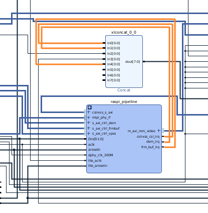
The interrupt numbers 104 through 111 are corresponding to pl_ps_irq1[0] through pl_ps_irq1[7]. Thus, make sure that:
imx_csiss_1 has interrupt 104, if csirxss_csi_irq is connected to In0 of xlconcat_0_0, which feeds to pl_ps_irq1[0]
imx_isp0 has interrupt 105, if dem_irq is connected to In1 of xlconcat_0_0, which feeds to pl_ps_irq1[1]
imx_fb_wr_csi has interrupt 108, if dem_irq is connected to In4 of xlconcat_0_0, which feeds to pl_ps_irq1[4]
GPIO
This does not require any changes, but the reset-gpio[86:82] in the .dtsi file corresponds to PS_0/emio_gpio_o[8:4]. You can see that the emio_gpio_o ius routed into raspi_pipeline to some rstn signals, and their position correspond to the gpio settings for each device in the .dtsi file.
I2C
On the KV260 carrier card, Raspberry Pi is on I2C port 2, so imx219 is on i2x@2 in the .dtsi file.
AFI Ports
Lastly, you changed the S_AXI_HP0_FPD port from 128 bits to 62 bits, so you need to set the AFI device in the .dtsi file. Configure 4, 5, to 1 to indicate 64 bits (0 = 128 bit, 1 = 64 bit, 2 = 32 bit):
config-afi = <0 0>, <1 0>, <2 0>, <3 0>, <4 1>, <5 1>, <6 0>, <7 0>, <8 0>, <9 0>, <10 0>, <11 0>, <12 0>, <13 0>, <14 0x0>, <15 0x000>;
Bitstream File Name
Change firmware-name to its corresponding .bit.bin file name. This step is optional because the reference is not being used by dfx-mgr.
firmware-name = "kv260-smartcam-raspi.bit.bin";
Clock Frequency
Because you changed one of the clocks from 300 MHz to 200 MHz, change the corresponding clocks (misc_clk_2) in the .dtsi file to 200 MHz:
misc_clk_2: misc_clk_2 {
        #clock-cells = <0x0>;
        clock-frequency = <199998000>;
        compatible = "fixed-clock";
};
Installing Drivers on Ubuntu
This step assumes you have installed SmartCam and are able to run the SmartCam application through the Docker container on Ubuntu. If not, to install SmartCam, follow the SmartCam app deployment instructions in Ubuntu 22.1 SmartCam app deployment page.
Testing the Platform on Target
Now, you need to test the generated platform to make sure the Raspberry Pi pipeline is working.
NOTE: You have not yet added in the DPU accelerator, so you cannot test the Raspberry Pi with SmartCam application itself until later.
First, SCP the kv260-raspi.dtbo kv260-raspi.bit.bin over to target or copy them to the SD card, finding them in /boot/firmware/, and reuse the shell.json file in /lib/firmware/xilinx/kv260-smartcam/shell.json:
sudo mkdir /lib/firmware/xilinx/kv260-raspi
sudo mv kv260-raspi.dtbo kv260-raspi.bit.bin shell.json /lib/firmware/xilinx/kv260-raspi
sudo xmutil listapps
sudo xmutil unloadapp
sudo xmutil loadapp kv260-raspi
sudo xmutil desktop_disable
If the hardware and the device tree is created correctly, you see Raspberry Pi in /dev/media0:
root@kria:~# media-ctl -d /dev/media0 -p
Media controller API version 5.15.39

Media device information
------------------------
driver          xilinx-video
model           Xilinx Video Composite Device
serial
bus info
hw revision     0x0
driver version  5.15.39

Device topology
- entity 1: imx_vcap_csi output 0 (1 pad, 1 link)
            type Node subtype V4L flags 0
            device node name /dev/video0
        pad0: Sink
                <- "b0040000.scaler":1 [ENABLED]

- entity 5: b0040000.scaler (2 pads, 2 links)
            type V4L2 subdev subtype Unknown flags 0
            device node name /dev/v4l-subdev0
        pad0: Sink
                [fmt:RBG888_1X24/1920x1080 field:none colorspace:srgb]
                <- "b0000000.isp_accel":1 [ENABLED]
        pad1: Source
                [fmt:VYYUYY8_1X24/1920x1080 field:none colorspace:srgb]
                -> "imx_vcap_csi output 0":0 [ENABLED]

- entity 8: imx219 6-0010 (1 pad, 1 link)
            type V4L2 subdev subtype Sensor flags 0
            device node name /dev/v4l-subdev1
        pad0: Source
                [fmt:SRGGB10_1X10/1920x1080 field:none colorspace:srgb xfer:srgb ycbcr:601 quantization:full-range
                 crop.bounds:(8,8)/3280x2464
                 crop:(688,700)/1920x1080]
                -> "80002000.csiss":0 [ENABLED]

- entity 10: 80002000.csiss (2 pads, 2 links)
             type V4L2 subdev subtype Unknown flags 0
             device node name /dev/v4l-subdev2
        pad0: Sink
                [fmt:SRGGB10_1X10/1920x1080 field:none colorspace:srgb xfer:srgb ycbcr:601 quantization:full-range]
                <- "imx219 6-0010":0 [ENABLED]
        pad1: Source
                [fmt:SRGGB10_1X10/1920x1080 field:none colorspace:srgb xfer:srgb ycbcr:601 quantization:full-range]
                -> "b0000000.isp_accel":0 [ENABLED]

- entity 13: b0000000.isp_accel (2 pads, 2 links)
             type V4L2 subdev subtype Unknown flags 0
             device node name /dev/v4l-subdev3
        pad0: Sink
                [fmt:SRGGB10_1X10/1920x1080 field:none colorspace:srgb xfer:srgb ycbcr:601 quantization:full-range]
                <- "80002000.csiss":1 [ENABLED]
        pad1: Source
                [fmt:RBG888_1X24/1920x1080 field:none colorspace:srgb]
                -> "b0040000.scaler":0 [ENABLED]
Once you confirm that Raspberry Pi has been connected correctly, start the SmartCam Docker container so that you have the necessary dependencies for the next command.
docker run \
--env="DISPLAY" \
-h "xlnx-docker" \
--env="XDG_SESSION_TYPE" \
--net=host \
--privileged \
--volume="$HOME/.Xauthority:/root/.Xauthority:rw" \
-v /tmp:/tmp \
-v /dev:/dev \
-v /sys:/sys \
-v /etc/vart.conf:/etc/vart.conf \
-v /lib/firmware/xilinx:/lib/firmware/xilinx \
-v /run:/run \
-it xilinx/smartcam:2022.1 bash
In the Docker container, now use the following gstreamer commands to display the Raspberry Pi sensor information onto a 1080p monitor:
gst-launch-1.0 mediasrcbin media-device=/dev/media0 v4l2src0::io-mode=mmap ! "video/x-raw, width=1920, height=1080, format=NV12, framerate=30/1" ! kmssink plane-id=39 fullscreen-overlay=true -v
Exporting the Design
Now that you verified that the Raspberry Pi pipeline is working, export the block design in Vivado Tcl:
write_bd_tcl config_bd.tcl
View a working version of this block design here.
A working version of the constraint is here.
Adding the Accelerator
In overlays/examples/smartcam/prj_conf/prj_config_1dpu, update clk because you changed the 300 MHz clock to 200 MHz.
freqHz=200000000:DPUCZDX8G_1.aclk
freqHz=400000000:DPUCZDX8G_1.ap_clk_2
freqHz=200000000:pp_pipeline_accel_1.ap_clk
Ensure that $kv260-vitis/platforms/vivado/kv260_ispMipiRx_vcu_DP/ip/ has isppipeline.prj/ from the previous step. This is necessary if you jumped in from the provided block design and pin constraints.
Copy the block design (config_bd.tcl), pin constraint (pin.xdc), and IP into the SmartCam overlay area that was generated in previous step.
cp  $kv260-vitis/platforms/vivado/kv260_ispMipiRx_vcu_DP/project/kv260_ispMipiRx_vcu_DP.srcs/constrs_1/imports/xdc/pin.xdc $kv260-vitis/platforms/vivado/kv260_ispMipiRx_vcu_DP/xdc/pin.xdc
cp config_bd.tcl  platforms/vivado/kv260_ispMipiRx_vcu_DP/scripts/config_bd.tcl
Now in $kv260-vitis, do a make clean so that the scripts regenerate ther platform with the updated artifacts when you call make overlay OVERLAY=smartcam in the next step:
make clean
Now you can run the makefile that was provided for SmartCam to put the DPU overlay into this platform:
make overlay OVERLAY=smartcam
After the makefile completes, the following displays:
$working_dir/overlays/examples/smartcam/binary_container_1/link/int/system.bit
$working_dir/overlays/examples/smartcam/binary_container_1/dpu.xclbin
Perform the following to convert system.bit to kv260-raspi-dpu.bit.bin:
cd $working_dir/overlays/examples/smartcam/binary_container_1/link/int/
echo 'all:{system.bit}' > bootgen.bif
bootgen -w -arch zynqmp -process_bitstream bin -image bootgen.bif
mv system.bit.bin kv260-raspi-dpu.bit.bin
Test with the Accelerator on Target
SCP kv260-raspi-dpu.bit.bin and kv260-raspi-dpu.dtbo (the same file as kv260-raspi.dtbo; you can reuse the same .dtbo file across designs generated from the same platform in this flow), and dpu.xclbin onto target. Create a new app:
sudo mkdir /lib/firmware/xilinx/kv260-raspi-dpu
sudo mv  kv260-raspi-dpu.bit.bin /lib/firmware/xilinx/kv260-raspi-dpu/
sudo mv  kv260-raspi-dpu.dtbo /lib/firmware/xilinx/kv260-raspi-dpu/
sudo mv dpu.xclbin /lib/firmware/xilinx/kv260-raspi-dpu/kv260-raspi-dpu.xclbin
sudo cp /lib/firmware/xilinx/kv260-raspi/shell.json /lib/firmware/xilinx/kv260-raspi-dpu/
Next, find facedetect’s preprocess.json file using sudo find / -iname preprocess.json | grep facedetect, and then update the file found on target /var/lib/docker/overlay2/<id>/diff/opt/xilinx/kv260-smartcam/share/vvas/facedetect/preprocess.json to point to the correct xclbin /lib/firmware/xilinx/kv260-raspi-dpu/kv260-raspi-dpu.xclbin. Do this outside of the Docker environment because the Docker container does not have a text editor by default.
Alternatively, launch the Docker container, install vim using apt-get install vim, and edit /opt/xilinx/kv260-smartcam/share/vvas/facedetect/preprocess.json from the Docker container. You must loadapp before launching the Docker shown as follows.
Execute the application with gst-launch, so that SmartCam uses the Raspberry Pi pipeline on /dev/media0:
sudo xmutil listapps
sudo xmutil unloadapp
sudo xmutil loadapp kv260-raspi-dpu
docker run \
--env="DISPLAY" \
-h "xlnx-docker" \
--env="XDG_SESSION_TYPE" \
--net=host \
--privileged \
--volume="$HOME/.Xauthority:/root/.Xauthority:rw" \
-v /tmp:/tmp \
-v /dev:/dev \
-v /sys:/sys \
-v /etc/vart.conf:/etc/vart.conf \
-v /lib/firmware/xilinx:/lib/firmware/xilinx \
-v /run:/run \
-it xilinx/smartcam:latest bash

check if above is true after release!!!!!!!!!!!!!!!!!!!!!!!!!!!! for now use:
sudo docker run --env="DISPLAY" -h "xlnx-docker" --env="XDG_SESSION_TYPE" --net=host --privileged --volume="$HOME/.Xauthority:/root/.Xauthority:rw" -v /tmp:/tmp -v /dev:/dev -v /sys:/sys -v /etc/vart.conf:/etc/vart.conf -v /lib/firmware/xilinx:/lib/firmware/xilinx -v /run:/run -it smartcam:latest bash
In the Docker container:
gst-launch-1.0 mediasrcbin name=videosrc media-device=/dev/media0 v4l2src0::io-mode=mmap v4l2src0::stride-align=256 ! video/x-raw, width=1920, height=1080, format=NV12, framerate=30/1 ! tee name=t ! queue ! vvas_xmultisrc kconfig="/opt/xilinx/kv260-smartcam/share/vvas/facedetect/preprocess.json" ! queue ! vvas_xfilter kernels-config="/opt/xilinx/kv260-smartcam/share/vvas/facedetect/aiinference.json" ! ima.sink_master vvas_xmetaaffixer name=ima ima.src_master ! fakesink t. ! queue max-size-buffers=1 leaky=2 ! ima.sink_slave_0 ima.src_slave_0 ! queue ! vvas_xfilter kernels-config="/opt/xilinx/kv260-smartcam/share/vvas/facedetect/drawresult.json" ! queue ! kmssink driver-name=xlnx plane-id=39 sync=false fullscreen-overlay=true
Congratulations! You should be able to see Raspberry Pi capture on the display port monitor, with a blue bounding box around the faces detected. In case you do not and want to test with a known working set of firmware, find them here, but be sure to update the folder name or file names and commands to align with each other.
Copyright © 2023-2025 Advanced Micro Devices, Inc.