AVED - User Application
Overview
The AMD Alveo Vivado™ example design lays the groundwork for building a custom solution. The example is delivered as source code to be easily updated and modified. It demonstrates the following features:
Pinouts targeting the Alveo V80 card.
CPM/PCIe instantiation and connections for host communications.
Programmable logic block diagram to support AMC firmware and AMI host driver.
Internal HBM, external DDR4 memory controller configurations and instantiations.
xbtest application example demonstrating I/O interface connection, traffic, and power.
xbtest validation example
The xbtest design instantiates the necessary blocks to provide PCIe® based host communication using the AMC firmware with the AMI drivers. The xbtest application validates functionality and connectivity to much of the optional external I/Os in the design. Additionally, a software application is provided to interact with the xbtest hardware.
Configuration
The main design configuration file is specified with a JSON file. The JSON file is read by the Vivado TCL and python scripts to generate and customize the design. The configuration file simplifies the need to modify multiple files/scripts to change basic characteristics of the design.
Configuration file format
The format of the JSON file is shown in the table below.
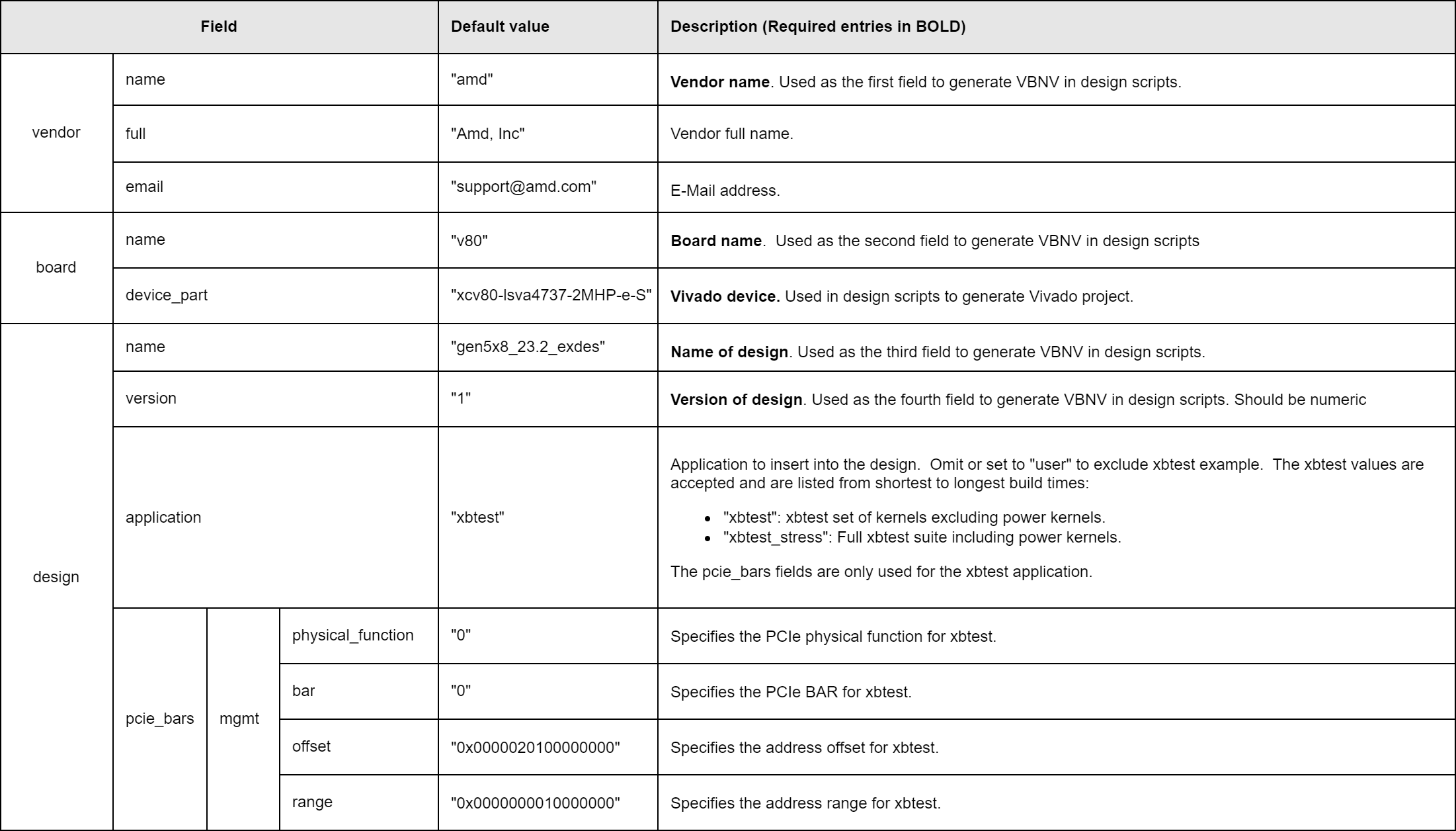
Configuration file example
The following is an example of the configuration file to instantiate the xbtest application example. The pcie_bars section is only used for xbtest and can be omitted for a custom application if it is not needed.
{
    "vendor": {
        "name"  : "amd",
        "full"  : "Amd, Inc",
        "email" : "support@amd.com"
    },
    "board": {
        "name"        : "v80",
        "device_part" : "xcv80-lsva4737-2MHP-e-S"
    },
    "design": {
        "name"        : "gen5x8_23.2_exdes",
        "version"     : "1",
        "application" : "xbtest",
        "pcie_bars"   : {
            "mgmt" : {
                "physical_function" : "0",
                "bar"               : "0",
                "offset"            : "0x0000020100000000",
                "range"             : "0x0000000010000000"
            }
        }
    }
}
Vendor Board Name Version
The vendor board name version (VBNV) identifier is derived from the configuration file and is used throughout the designs to generate the output products. It is composed of the fields in the configuration file with the following format:
<vendor.name>_<board.name>_<design.name>_<board.version>. The VNBV is used to find source files and to generate the output file paths. To change the name of the design, update the appropriate fields in the configuration json file. The VBNV of
this example is amd_v80_gen5x8_23.2_exdes_1. If the VBNV is changed, a new ./hw/<new VBNV> sources directory is required to match the new VBNV. The default output directory defaults to ./output/<VBNV>/<timestamp>/ .
Customizing the design for a new application
The following steps provide the instructions to modify the xbtest example design to create a custom user design. This example workflow will use the design without any existing hardware application as a starting point.
The
./hw/amd_v80_gen5x8_23.2_exdes_1/conf_user.jsonconfiguration is used as the starting point. This configuration has the application set to “user” which will instruct the tcl scripts to only instantiate the base design. It is recommended to copy the file to a new file if customizations are required. Keep in mind any fields that adjust the VBNV will cause the source and output directories to change.Add any custom/new IPs to the
./hw/<VBNV>/iprepodirectory to have them automatically added to the IP Catalog during design creation.(Optional) Modify the existing XDCs in
./hw/<VBNV>/constraintsif necessary and remove pinouts of I/O that will not be used. This is not strictly necessary, but will reduce the amount of CRITICAL WARNINGs and WARNINGs in the design. If additional constraint files are added, then modify./hw/<VBNV>/build_hw.tclto add them to the design automatically.XDC files that specify constraints that depend on existing clocks should have
processing_orderset toLATEso that they are applied after the clocks are created.Run
./gen_design.py --gui --conf ./hw/amd_v80_gen5x8_23.2_exdes_1/conf_user.json
to launch Vivado into GUI mode with just the base design. The script instantiates the AVED design base logic and then hands off control for interactive modifications. The design is ready to be modified. Make necessary changes to the block design as needed and ensure the design can validate cleanly.
- When the design is ready to be implemented, execute the tcl proc
do_aved_buildin the Vivado TCL console. This will complete the rest of the build steps including synthesis and implementation. It will also automatically issue awrite_bd_tclcommand to create a tcl script of the final bd design here:<output_directory>/bd_gen/create_bd_design_final.tcl. This file can be copied over the <sources>/bd/create_bd_design.tcl file to automatically include the updates for future./gen_design.pyinvocations.To save the bd file manually, the recommended command is:write_bd_tcl -force -no_ip_version -hier_blks [get_bd_cells /] <file.tcl>
Once the device image has been successfully generated, the script will report it is done. Close Vivado to allow the python script to continue with the rest of the build flow.
When the
gen_design.pyscript completes successfully, the final PDI will be generated in the output directory:./output/<VBNV>/<timestamp>/pdi/fpt_setup_amd_v80_gen5x8_23.2_exdes_1.pdi. The final pdi is generated and is ready to be tested on hardware.
Page Revision: v. 23