UL3524 Ultra Low Latency Trading |
GTF Latency Measurement Design: Simulation
Overview
Details how to simulate a reference design using the provided waveform .wcfg file. And provides details on important signals to review.
Instructions
Use the following steps to simulate the reference design:
Start Vivado and load the project
Select Simulation->Run Simulation from within Vivado. All reference designs come with a simulation waveform file.
This will:
Start the Vivado simulator,
Load the waveform .wcfg file and
Display the selected signals.
Click on Run All
The simulation will run until completed.
Update the desired signals in the waveform and rerun as necessary.
Simulation Behavior
The simulation will run for approximately 140ms. The resulting waveform, below, shows the behavior of the GTF Mac data stream, both TX AXIS data into the GTF and the returned RX AXIS data. The external GTF serial I/O begin toggling at 116ms.
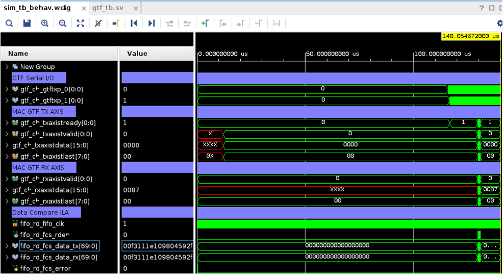
Figure: Waveform of the GTF latency measurement in MAC mode
Zooming closer to the data stream, the individual TX and RX 16-bit data words can been seen before and after the alignment FIFO’s.
Picking a data word being sent on the TX AXIS interface, it can be seen a few clock cycles later on the the RX AXIS interface.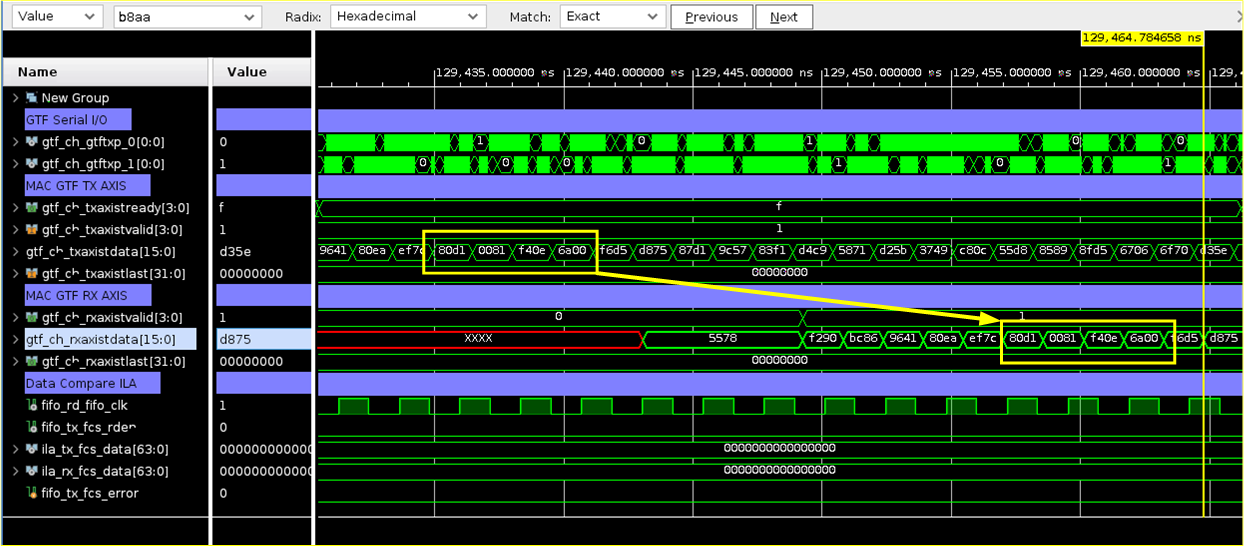 Figure: Delay in TX and RX Data
Each bus packs four words and stored into the FIFO’s as a 64-bit word.
Shortly after the RX/TX words are stored in the FIFO’s, a common clock reads both FIFO’s and compares the data as shown in the following figure.
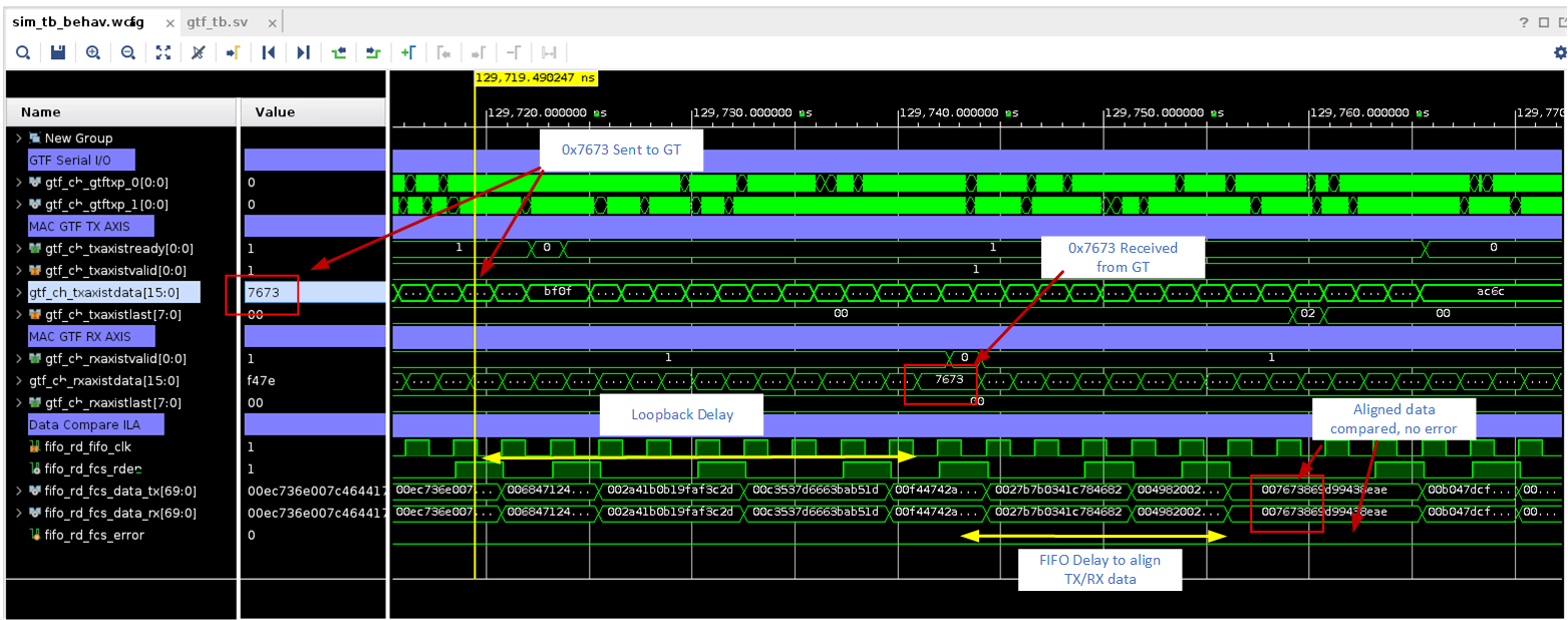
Figure: Detailed Delay in TX and RX Data
The data compare logic consists of two dual port FIFOs that store the RX and TX data. When both FIFO’s have contents, the logic will pull from both FIFO’s and compare the contents. If a discrepancy is detected, the fifo_rd_fcs_error bit is asserted.
NOTE: ILA placeholders are included in the RTL allowing these signals to be used to view compared data and error flags. However, since each serial channel has it’s own ILA (4 ILA’s for 4 channels), this can can create routing congestion and negatively affecting timing closure during implementation.
Support
For additional documentation, please refer to the UL3524 product page and the UL3524 Lounge.
For support, contact your FAE or refer to support resources at: https://support.xilinx.com
Copyright © 2020–2023 Advanced Micro Devices, Inc